

jgazal
-
Posts
175 -
Joined
-
Last visited
Content Type
Profiles
Forums
Events
Everything posted by jgazal
-
Is this correct? Fully complementary = signal path is balanced, so every noise that enters both paths with the same phase will be canceled each other. Fully differential = a bipolar power supply is used, so the power supply rails are balanced and every noise coming from the mains with same phase in both power rails (the positive one and the negative one) will be canceled each other. Symmetry = it is all about symmetric topology, then loops are better controlled in terms of delay (if any, considering the velocity of the electrons in such circuit) and phase reversions (the signal coming from the loop enters the first stage with the wrong phase). I was wondering if point to point circuits with circular traces and input and output very close each other would be someway beneficial. What do you think about phase splitters in the input? I think Woo Audio WES has something like that.
-
Directly from the source:
-
You are absolutely right. I have these CD's: cduniverse.com - Richard Strauss (Also Sprach Zarathustra) - Camille Saint Saens (Symphony No.3 -Organ) cduniverse.com - Pearl Jam (Binaural) I also have a demo disc from Ultrasone (just the disc, not the headphones). They are all very good. What I was trying to say is that I always searched for out of the head lifelike "sound image" (avoiding to use the term “sound stage”). While binaural recordings really do the trick, it is usually presented in the back of my head. Perhaps your pinnae etc. is similar to Neumann KU100. In-front localization is very poor to me. It is said that sounds coming from your front does not have delays or frequency deviation, thus you unwittingly slightly turn your head so that your brain is able to calculate where they come from. That's why that DSP I have mentioned also use head-tracking and it lets you measure the center channel of a multi-channel home theater system so that you can measure it right there where your TV is going to be during the playback. It also lets you to control the speaker’s azimuth so you can virtually place them wherever you like and to alter the room reverberation. It is a piece of very solid audio engineering knowledge (primarily an algorithm). I also have the same disappointment with cross-feed circuits some years ago. I thought it would be a 3D revolution. And it was just a subtle effect which kept images inside my head... I just wanted to let this clear. Binaural recordings really help to retrieve the venue tonal ambience (reverberation, reflections etc.), but it does not retrieve the 3D “sound image”. No need to mention that such DSP comes with an electrostatic headphone and amplifier combo. They had feared that users would blame the DSP for deficiencies in their current headphones (poor ones like ear buds etc.) so they have chosen to sell it with a faithful headphone (SR-202 + SRM252II). This might be evidence that any electrostatic headphone is generally suited for binaural recordings. What does really make a difference is HRTF matching (call it personalization if you want). Best regards, Jose Luis
-
I hope I did not say something wrong... Okay, just one more and I will keep my mouth shut. There is an alternative cheaper way to test idiosyncratic binaural recordings. If you want to make your OWN binaural recordings, you might want to use these microphones: Sound Professionals SP-TFB-2 or Microphone Madness MM-BSM-8 or Soundman OKM If you want to record loud sounds, hook them into the line-in jack of a portable digital audio recorder (i.e. Sony PCM-D50) using a battery pack (i.e. Sound Professionals SP-SPSB-10). For quiet sound you are able to hook them directly into the pre-amp jack of the portable recording (which already has plug-in power, although not optimal). These microphones have some noise of their own (small diaphragms), but with moderate sounds you will not notice. With quiet sounds you will hear some kind of hiss. The best part of it: you rarely were into the recording venue so you do not know how it sounded originally in real life. With you own binaural recording you have a faithful reference to judge your playback equipment fidelity. Even sounds on the street might be your reference recording. Of course these microphones have their own fidelity limitations (even the MM higher version with Sennheiser capsules), so take it with a grain of salt... It is impossible to use a large condenser microphone to mimic your HRTF... I believe the ultimate (and expensive) solution is a regular recording with better microphones (large membranes) and a DSP doing all the HRTF math somewhere in the playback chain. Best regards, Jose Luis
-
People usually recommend newbies to stay quiet, but I will try to add a bit of information. Binaural recordings are usually based on dummy head microphones. The outer ear (pinnae), the distance between diaphragms (mimics the distance between your tympanic membranes or at least the entrance of your auditory canal) and torso reflections and absorptions will not match the way it happens with the vast majority of the population. Head Related Transfer Funtion (HRTF) is idiosyncratic. You have your very own and a limited parcel of the population will have a similar one. If you want to take normal stereo into a personalized HRTF stream, then you have to measure your own HRTF and use a DSP to do the job. There is still no database to search for average HRTF that match your own one. And guess what, there is a product that does exactly that (it uses a microphone placed exactly in the entrance of your auditory canal). It is called Smyth Realiser A8. It is really expensive (USD3400). I have not bought it. It will transform any regular multi-track recording (up to 8 channels) into a lifelike 3d sound field. There was a military research using similar concept in airplane cockpits, but they used to measure the HRTF of the pilot into an anechoic chamber. Reversely HRTF “reads” the reverberation and other cues of the room given its sound signature. I am still waiting for a two channel cheaper version... It will take years... Anyway, it is a breakthrough so early adopters shall be willing to pay the current premium price. Best regards, Jose Luis
-
Which is best? Linear LSK389-C TO71 (metal can) or Toshiba 2SK389-GR?
-
"Gamma ray shield".
-
Are there different versions of the SRM-t2? Japanese manual says it has 50 kilo-ohms (single ended) or 100 kΩ (balanced) input impedance: [url=http://earsp.web.fc2.com/log/manu/srmt2/t27_jpg_view.htm]STAX
-
This is a great thread and that is a great tip. 2SK389/LSK389/2x2SK170 always was/were my main concern. I did not know Ti-Kan was matching them. Fantastic!
-
You’re both right. Now I see the nonsense I said. I recall a in-ear Shure I used to have with plenty of bass...
-
I was wondering if the absence of a big resonant structure in the SR-003 could make a more focused soundstage (at least compared to SR-202, SR-303 and SR-404). Is this the case? That
-
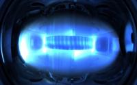
Thanks for clarifying. They have reached the first 7 TeV collision! I wish I could go to CJ2010!
-
Large Hadrons Collider – LHC consumes 1% of liquid nitrogen produced in the whole world to induce its superconductors. 30 fellows forcing gas refrigeration into theirs T2's would consume almost the same... Then labs would have to pay more for nitrogen with the increasing demand. But they use that for physics, medicine etc. People use T2 for music, funny thing... Would not be better (cost efficient) to water cool only the semiconductors (like core processors in PC’s)? How much distortion is induced by heat on capacitors, resistors etc?
-
I know that you were going to comment that anyway, but it would be nice to have your opinion about differences between SR404 and both Omega's when they are being driven by T2.
-
Thanks! I was already asking to stick his post and let mine floating. Regards, Jose Luis
-
 I think people here at Head-Case should know that Twisted Pear Audio is raising funds to support Doctors Without Borders relief efforts in Haiti after the earthquake. There is a prize, to be precise a complete Buffalo II kit! http://www.twistedpearaudio.com/news.aspx Best regards, Jose Luis
 -
This DIY design is fantastic and Mr. Gilmore is doing an astonishing work. I know that it is very impolite to give opinions when you are a layman and not proficient to suggest alternatives, but I would like to ask a few questions regarding air circulation. More holes are needed for dissipating tube heat or resistors heat? If they are required to dissipate heat deriving from resistors, should those holes be placed near/around the tube sockets in the DIY SRM-T2? Justin could explain why he decided to do BHSE holes this way: Regarding the DIY SRM-T2 chassis and PCB integration, are those resistors placed at the tube sockets PCB side (above side) or at the internal PCB side (below side)? Correct me if I am wrong, but I think there was surface mount resistors below the PCB in the original SRM-T2. BHSE too: If the DIY SRM-T2 has them placed below, how the heat can raise to the above side (tube sockets side)? Again, correct me if I am wrong, but I have not seen wholes provided at the DIY SRM-T2 PCB (like BHSE) to do that task besides those at the outer limits where the semiconductors are soldered. Are those pcb outer holes sufficient to let air circulating? If hot air is arising, shouldn’t be good to have holes above the chassis to let cold air entering the chassis? Or XLR, RCA, IEC and other connectors already let air enter the chassis interior? Last but not least. I have been reading that a faraday’s cage is very difficult to achieve. Once you have one hole, EMI or RFI is entering the case. Is that somehow frequency dependent (refraction)? If not, more holes would not be prejudicial, would them? Should 6DJ8 be shielded like they were at the original SRM-T2 to accomplish that purpose? Regards, Jose Luis
-
The head related transfer function (HRTF) is extremely idiosyncratic. Why don
-
Is this what you are looking for? Rapid Electronics - Cables & Connectors Sorry, only UK... And they seem quite expensive...
-
What's the difference between Spritzer's SRM-T2 (which is the paradigm of this DIY project) and this one below?
-
I thought that adding a couple of 3-phases dynamos in series with slightly inclined stators (therefore slightly delayed phases) could decrease ripple, although not sure if it is feasible with high voltages and other consequences as I am not an electronic engineers. Just imagining things I do not really know and trying to understand. Would it be a pulse? p.s.: picture from wikipedia
-
First of all, I am not an electronic engineer so I might be asking something really stupid, but I will try anyway. If the question does not deserve any answer, leave it in blank and I will kindly understand. I have been following Kevin Gilmore dc coupled designs and this gorgeous dc coupled amplifier and its power supply counterpart are food for thought. I comprehend that voltage and current come in alternating at 60Hz. But what does it mean to have a fully dc coupled signal path if the power supply needs to handle the 60Hz ripple with capacitors? Aren’t them adding some ripple (or helping to attenuate it) right in the signal path? I have been reading recently that power line is going to be used to send and receive data. I presume that this modulation will occur at very high frequencies, much higher than the audio spectrum, but, still, I think this will adding be some kind of distortion to audio power supplies and circuits. This new power supply is able to cancel/attenuate that THD better than others? Well, I presume that bigger transformers doing the current/voltage modifications, diode rectifiers converting AC in DC and those well dimensioned capacitors do help a lot. But, what if power supplies were made with "dynamos"? I know that this brute force approach would increase costs with moving parts, as well as wasting more energy with heat dissipation, friction and the consequent physical hum. But is this much more inefficient than power supplies with rectifiers? Please imagine cost is no problem (I recognize that diodes shall be cheaper than building dynamos...). I was thinking that building a dynamo with several phases in series would produce a low ripple dc stream and avoid the power supply capacitors. Then we could call it real fully dc coupled amplifier. How much of the power line THD in higher frequencies would interfere in the dynamo rotation? I feel that this kind of construction would also reduce the power line THD in the audio circuit. Last but not least. Is it possible to build a dynamo silent enough for audio purposes? This might sound economically impracticable, but I just want to know if it is theoretically possible and better. Best regards, Jose Luis
