kevin gilmore
High Rollers
-
Joined
-
Last visited
Everything posted by kevin gilmore
-
so pars posted this. http://www.diyaudio.com/forums/group-buys/315474-pure-tube-es9038pro-9028-9018-akm.html#post5259820 all sorts of wrong. lets start with the fact that current output D/A converters really like driving a zero impedance. 27 ohms is not a zero impedance. So with +/-1.2ma you get +/-32mv and then you use the tube to amplify the crap out of it. Nope, definitely not the way to do this. All sorts of noise etc... a while back there was bakoon and audio-gd pointing fingers at each other as to who designed satri and when. so here is the satri version 4 circuit satriic.PDF and here is how audio-gd turns it into both the I/v converter and acss current output and voltage output (one at a time, not both) audiogdiv2.PDF performs better than anything else I have seen ideas in progress as work on the ultimate dsd/r2r dac
-
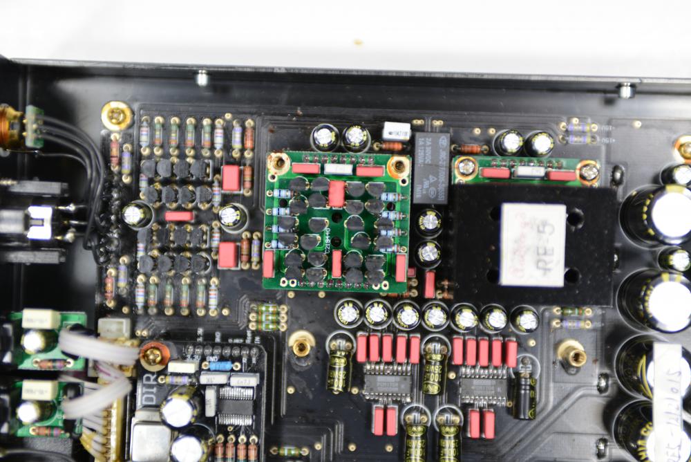
servo attaches directly to the plate of the tube. similar to T2. no way to make less complex.
-
-
current mirror flips the polarity, so you have to flip the polarity on the opamp. the difference between the 2 servo's is something like 1mv at 7 volts peak to peak output. so very little difference.
-
no that is not correct. here is the schematic, and I hope the board matches it cfa2cmirror.PDF
-
grlvplus and grlvminus are the singles split off the original board
-
trying to build a ssdynahi on the cheap, probably not a good idea.
-
the pot and the 2 associated resistors are the optional parts. and the values of the resistors change depending on what voltages you want. none of the 4.5 digit dvm's are accurate enough. Especially since if you reverse the leads you get different numbers. In fact 6.5 digit dvm's are just barely enough and the keithely ones in particular read different numbers if you flip the leads. The agilent ones do not. 7.5 or 8.5 digit dvm's highly recommended.
-
You need all the resistors if you want to adjust the voltage. Otherwise too noisy. The adjust is calculated for about .1% range
-
shunt regulator for more than 1 amp and 30v, probably a very bad idea without massive heatsinks and really large pass devices B22 also struggles with this due to high voltage differential. I.e. lots of heat
-
ss dynalo has the servo's in the same place as the cfa amp. the audio signal is nowhere near as much as that in the ksa5, but still the quality of the servo opamp can have some slight effect. I can possibly measure the difference, but don't know if I can hear the difference.
-
continuous improvement basically trading one opa445 for a opa551, 4 transistors, 5 resistors and 1 cap probably should do the same thing to the ss dynalo.
-
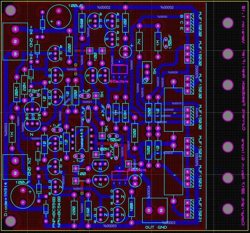
newest version of the current feedback amplifier with the servo not in the audio circuit so that you can use cheaper opamps. But if you run 30v, you still need 30v capable opamp. Like opa551. what the noise difference if any, I don't know yet. cfp2hmt.zip
-
The ones I used were metal film, don't remember which ones inductive things on outputs are a bad idea
-
that is probably close. ksa5 has a fet input stage.
-
Slight DC offset unless you match input parts. So a whoosh as you turn the knob
-
probably a good idea to use 60V transistors for 30V power supply
-
that is a bit too much solder on the tab, but it should be fine
-
the pair of output transistors run at about 200ma the drivers at about 20ma vbe transistor runs at about 10ma
-
there are now 2 versions of this, one with the tube on the component side, and the other on the back side for mounting megatron style. ask first.
-
Make sure the toshiba are the matching pinout
-
-
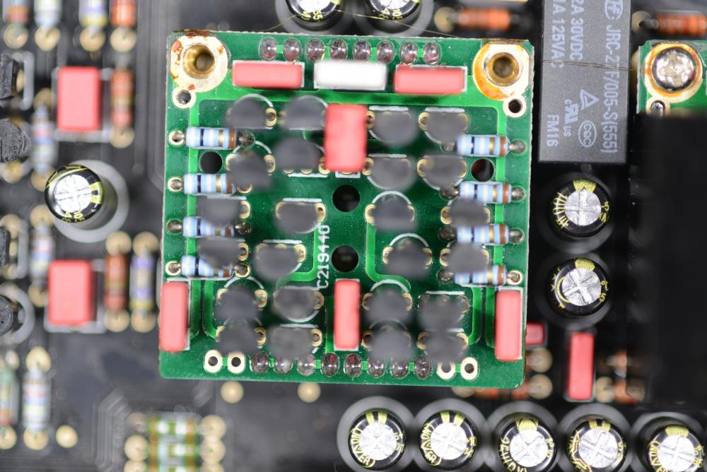
they were the original cascade transistors in the dynahi. can be used as a bipolar input on ssdynalo and ssdynahi. and anything else that has the that340 footprint. also current mirrors for doing servo and a few other things I may come up with. all the fet input options are brutally expensive these days this is another place that has the pins http://www.king-cart.com/phoenixent/product=HEADERS-MACHINED-PIN+BREAKAWAY+.1SP/exact_match=exact
-
those won't fit in a milmax socket need round pins .018 inch diameter for the socket end
-
nope, real product. someone here bought one. maybe originally they had a plan for those 2 extra tubes. I see that the current version has options for dynamic outputs, so maybe the extra tubes have found a use