kevin gilmore
High Rollers
-
Joined
-
Last visited
Everything posted by kevin gilmore
-
with the opa134 you are limited to 36v. you can certainly change that opamp to opa445 and then it would work up to higher voltages. going to check on the ratings of the transistors now edit: subject to the voltage ratings on the capacitors, so probably 35v
-
from Kerry, the gr78xx and gr79xx board files I want a few of each if there is going to be a group buy GR79xx.zip GR78xx-v1-2.zip
-
-
yes but the opamps are wired regulated to ground so a opa134 is good for up to 36v output voltage
-
direct sunlight is definitely a bad thing
-
8.7 sp1 as of 1 month ago, but a lot of the stuff should be 8.4 or earlier try a standard gerber viewer. there should be no configuration or setup issues
-
All the newer gerber x2 stuff most likely. Can't make older gerber files with the new software
-
that340lsk.zip
-
I have always wanted a revox a700, but have absolutely no use for it. All it would be is a time sink to keep it working.
-
http://www.chicagotribune.com/entertainment/music/reich/ct-ent-willie-pickens-dead-1214-story.html
-
to save space I sometimes do vertical resistors. but everything else is wrong with that amp.
-
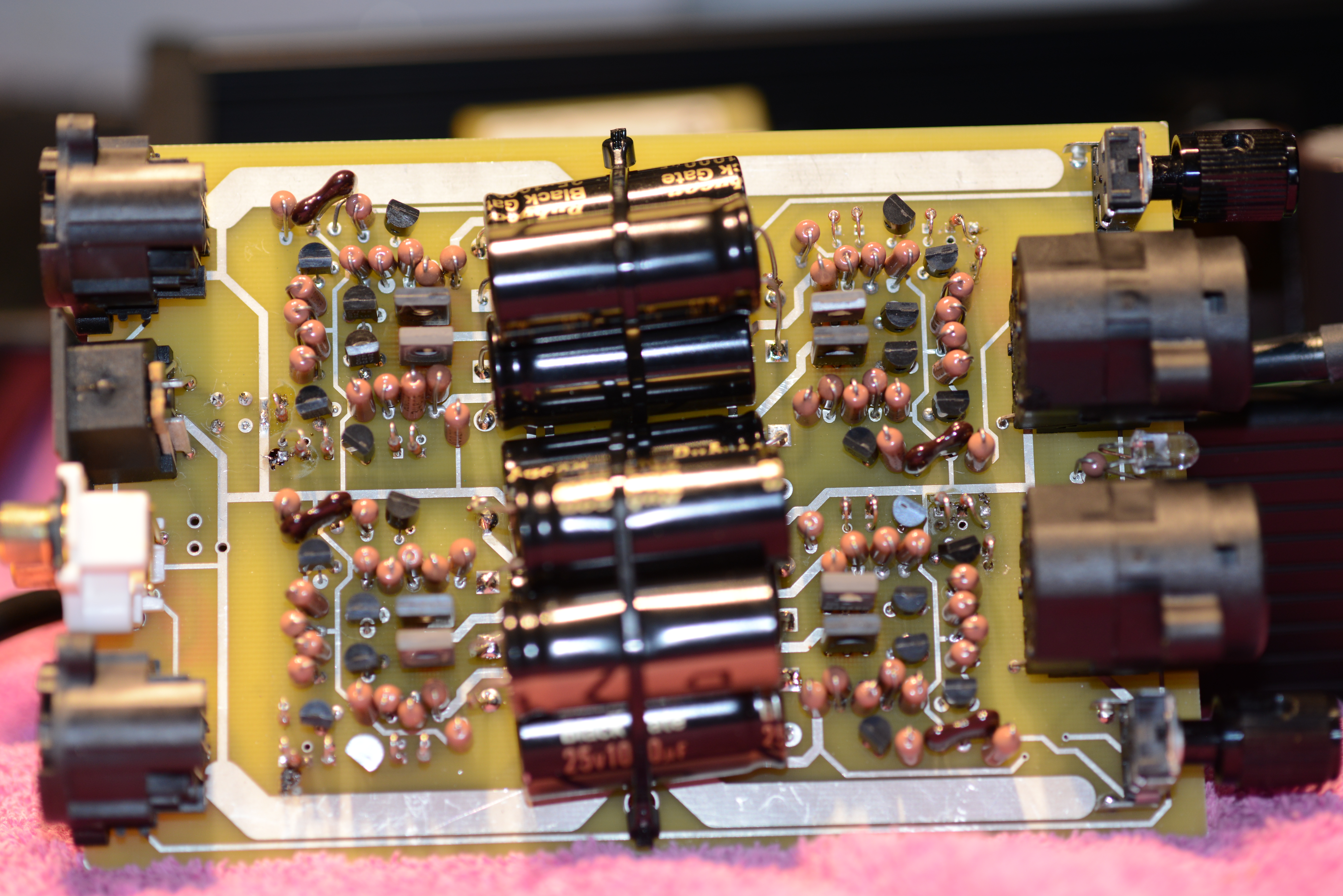
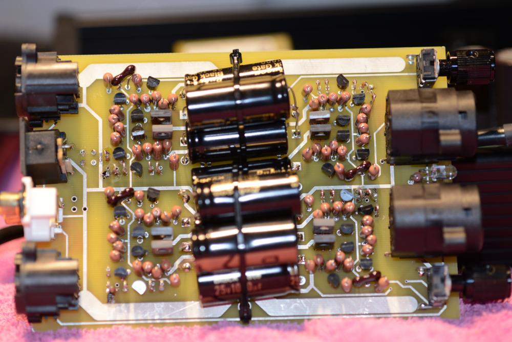
no servo so blackgate output caps on a solid state amplifier taking 1/3 of the board space. yep, great idea
-
here is why you probably don't want one unless its dirt cheap. you will need to add heatsinks, not easy, and fix all the acetate failure

-
the singlepower squarewave definitely does not like low impedance loads (50 ohms) making it balanced causes even more trouble. very few of the balanced versions were built, and they are balanced out only when balanced in, and depending on the power brick, they burn up real easy.
-
definitely not.
-
what transistors are you using?
-
even the ksa992/ksc1845, one of them is on backorder till February and i'm going to need them.
-
Mmbt are surface mount so no you have to check the pin outs for the rest
-
ss dynalo already has the pot, just don't populate the opamps
-
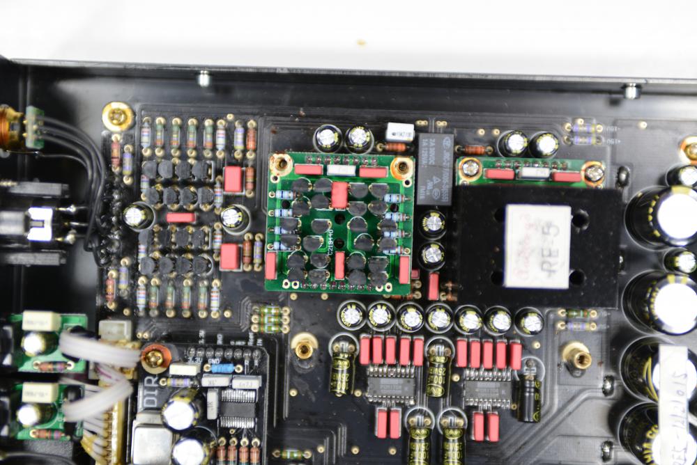
this one http://www.audio-gd.com/Pro/dac/RE52/RE5.2EN.htm around 2013 time frame. very nice sounding piece, but no dsd
-
pin 5 on the opamp is not a NC, so if you want to do this and put a jumper from pin 4 to pin 5 on the back of the board cut off pin 5 of the opamp, or bend out of the way. the best servo of course is no servo at all as long as everything is stable with temperature
-
better idea would be to use the servo from the kgsshv-carbon but does not compensate for the tube drifting section to section
-
so pars posted this. http://www.diyaudio.com/forums/group-buys/315474-pure-tube-es9038pro-9028-9018-akm.html#post5259820 all sorts of wrong. lets start with the fact that current output D/A converters really like driving a zero impedance. 27 ohms is not a zero impedance. So with +/-1.2ma you get +/-32mv and then you use the tube to amplify the crap out of it. Nope, definitely not the way to do this. All sorts of noise etc... a while back there was bakoon and audio-gd pointing fingers at each other as to who designed satri and when. so here is the satri version 4 circuit satriic.PDF and here is how audio-gd turns it into both the I/v converter and acss current output and voltage output (one at a time, not both) audiogdiv2.PDF performs better than anything else I have seen ideas in progress as work on the ultimate dsd/r2r dac

-
servo attaches directly to the plate of the tube. similar to T2. no way to make less complex.
-