kevin gilmore
High Rollers
-
Joined
-
Last visited
Everything posted by kevin gilmore
-
-
lampizator continues to advertise a DHT Plate Follower with a Voltage gain of +1 with a single triode. Not in this universe. Its crap like that, and transformers secured with double sided tape and a Mikhail class soldering job that tell me to run away fast. 20 years ago when the T2 came out, there was no such thing as a 1600v SicFet. Tubes were then the best way to do high voltages. There is a 4500v SicFet coming soon. Its going to be a bit pricey. But solid state direct drive electrostatic speakers will soon be possible. by the way you do know what birgirs middle name is right?
-
yes you have to use silicone grease on both sides. or thermasil on both sides for less mess
-
for the grlv, no reason to use the aluminum oxide insulators. the standard ones are just fine and don't make a mess.
-
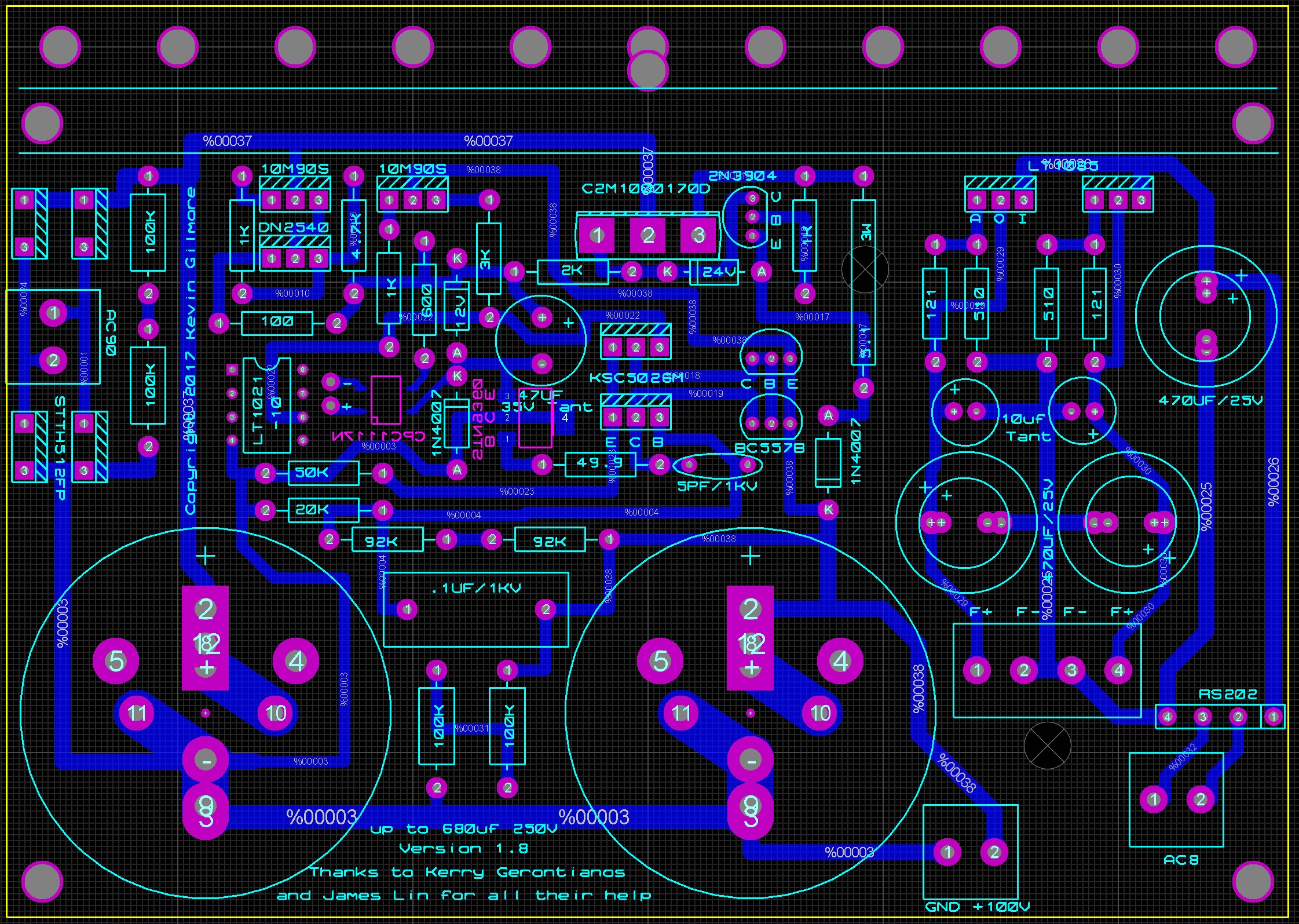
board files for you updated including 100v massive overkill power supply ubaltobaltube.zip grhv100v.zip

-
this makes me smile a lot
-
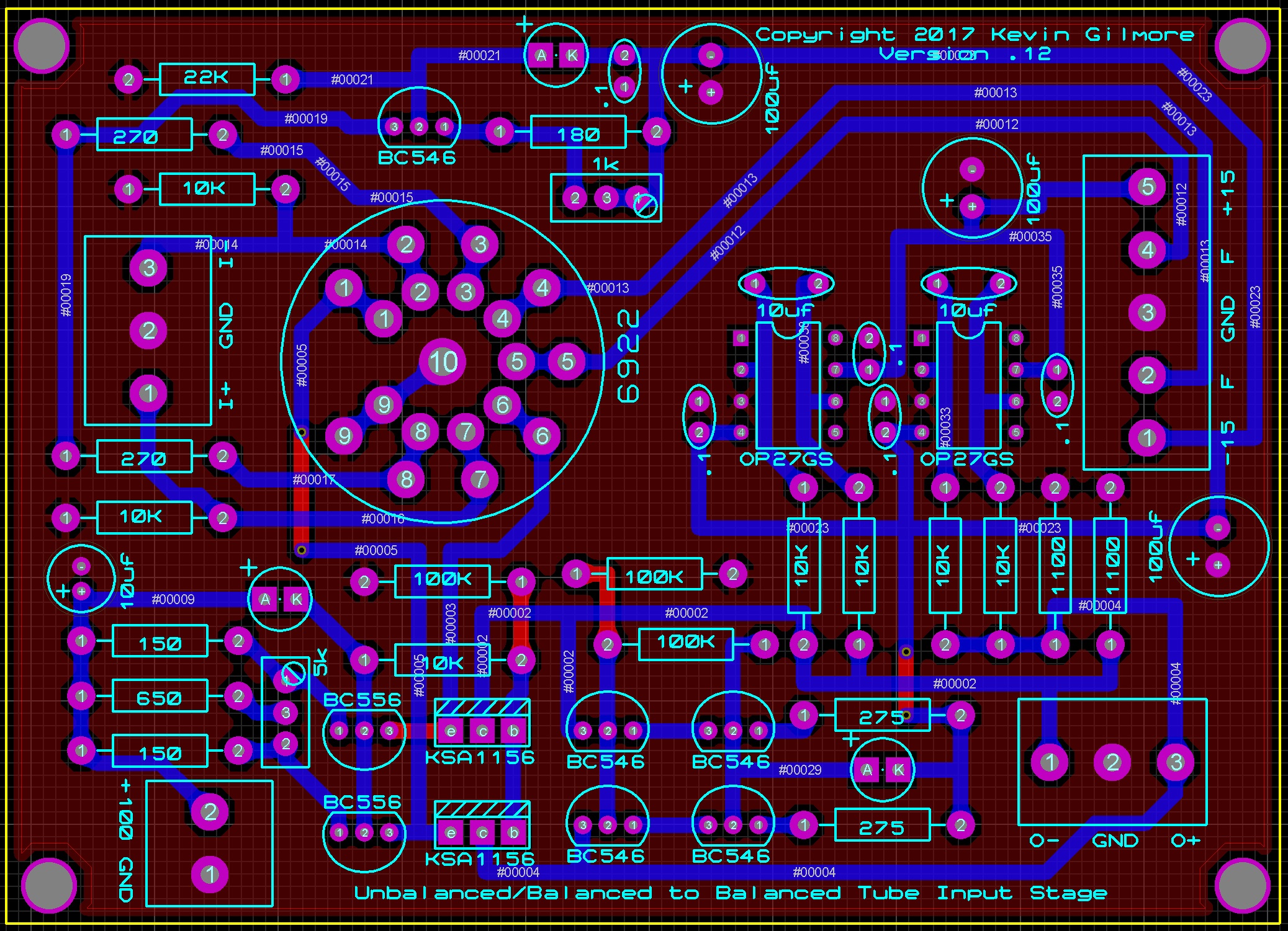
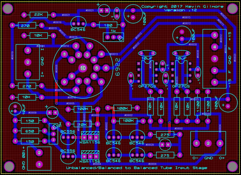
So I've been looking at a bunch of tube/solid state hybrid dynamic amp schematics, and every one of them is some form of bad, or really bad. (one person/ex company in particular) Low voltage plate, capacitve coupling of a high impedance source into a low impedance, poor balance etc. There had to be a better way. true balanced input. dc coupling. low impedance output. no feedback. proper use of a tube (pure transconducance) etc so I came up with this, work in progress. 4 x 3 inches ubaltobaltubeschem.PDF
-
About 450 usd
-
I was thinking the other board. Yes that board gets that hot due to the transistors you can add heatsinks
-
-
that is hotter than I expect, what voltage rails and what voltages on the led's
-
yes its a goldenreference clone, but without the lt1010 reference chips. So they went with something a bunch cheaper for the reference. also they turned the tantalum into electrolytic which adds a bit more noise. still for the price, I can't even buy all the parts the way I build them for what they are selling it for.
-
Those are a clone of my older boards, but a different power supply. For the price looks like a great deal. Looks well built sanded off chips in the power supply a nice touch
-
1 amp at 30 volts times 2 power supplies is the same as 1 amp at 60v same total power
-
no idea, evidently lots of stax mafia stuff on taobao. The one guy took my power supply layout, copied it 100% then added stuff and changed the form factor and holes...
-
that is the ss dynalo balanced version with the mpsw transistors. which you are going to have a hard time finding. this is not the original unbalanced dynalo.
-
A 4 pin plug does not mean it's balanced the liquid Crimson is not balanced
-
the only one with a lifetime warranty was the liquid carbon version 1. https://item.taobao.com/item.htm?spm=2013.1.20141003.7.4edb00b7muYKyQ&scm=1007.10011.70203.100200300000001&id=560442101039&pvid=d455e4ef-3a60-417c-9653-9dc0aea4d782 this guy will repair your piece of shit for you, the shipping both ways is going to be more than a liquid carbon is actually worth. my offer to ONE and only ONE person, send me your liquid crimson (the only one I don't have schematics of) and I will fix it for free. (plus parts and shipping) options can include turning the output stage into bipolar.
-
like this, one side, replace r7,r8 with 10k pot electroopamp.PDF
-
that cannot work with the + inputs of the opamps grounded.
-
quite a bit more power and heat and bigger power supply etc
-
the second schematic is not going to work, there is nothing to keep the output at +300, the left side of R4 needs to go to some negative value and AGAIN, the dn2540 will BLOW UP when the voltage across it hits 400v use a bsp125 in the to220 package if you want a 600v power supply but much better is a c2m1000 and a 900v power supply
-
the massdrop is a liquid carbon. not a liquid gold. lower voltage power supplies, less heat, less power etc a correctly built liquid gold is at least 50 watts of heat. but hey its cheap
-
the 2 channel pot to do balanced is the same crap eddie current uses. it can be made to work, but causes all sorts of problems. All 4 wires are with respect to ground so not what you think. Also you need a reverse log pot for it to work right, and no one makes those. electrostat, dn2540 goes boom at anything over 400v. and its a depletion mode part, so not a great idea. what you are doing is a hev70 copy, look at the original for better ideas. also the opamps driving the mosfets have the feedback wrong.
-
its always better to match parts, less work for the servo