kevin gilmore
High Rollers
-
Joined
-
Last visited
Everything posted by kevin gilmore
-
those JJ tubes have only 1 hole in the plate per side, the originals have 3 holes and a different configuration of the plate, more square than rectangular. my T2 is still using the same tubes as when I demo'd it at CJ010. I recently did a 100 to 120V conversion on a real T2 for someone on HF. It has the original tubes, 22 years old. (pictures can be supplied if anyone has a real T2 and wants to convert voltages, better than $250 in shipping both ways) The gold aero's are labeled 6dj8
-
so on the input tubes the input tube has a plate voltage of roughly +75 volts and a cathode voltage of -3 volts the cascade tube has a plate voltage that would be a max of 250v, but its a current source, and is typically +200V and a cathode voltage of +75 volts and the maximum voltage swing is about 15v so both tubes well within specifications closer look at the original pictures and the original tubes are el34G they look absolutely identical to the Richardson tubes currently made in china which are labeled as 6ca7
-
The real original has el34 with the Richardson electronics National Logo made in USSR about 1994 the 6dj8's were gold aero
-
lots of floating filaments
-
although a lot more parts, and not all tubes, the T2 battery appropriately adjusted for voltage to replace the loss across the 0a2. of course you could just use a 1uf cap across the gas tubes
-
ssdynahi has a lower input impedance and would be fully balanced.
-
r19 in parallel with r20 is the gain resistor
-
that definitely works, but the price is a bit goofy. probably what happens when you spend 10 years trying to make better parts only to make parts identical to the originals
-
lh0033 is a diamond buffer, and is VERY obsolete. I have a couple of originals somewhere.
-
That was a jpg picture, the schematic above is the latest
-
that is the correct schematic with q27 and q28 replaced with surface mount on the back of the board
-
lg.zip note: phase splitter not included you need 4 for balanced
-
so after thinking about it a while, something is wrong with the hv delay circuit which turned on with the tubes cold. this has to be fixed first. when the tubes are cold, the output voltage is going to go to +500v, and thru the 100k feedback resistor is going to put 500v on the cathode of the input tube. With the filament of the input tube grounded, there is 500v cathode to filament. Guaranteed to cause a light show and permanently trash the input tubes.
-
-
it would be nice to come up with some universal layout that would take all the available options that340, 4 x single jfet,2 x dual jfet,2 x dual bipolar... yes pars posted the picture I was thinking of, I even found the board
-
I did post a picture quite a while ago of the 4 jfets soldered to a milmax socket. definitely the easy way finding the picture might be harder
-
that definitely does suck, I had one noisy one out of a batch of 10. birgir is making a little mini board, and Justin bought a pile of dual transistors, might be a better solution the layout of the amp is such that you can replace the that340 with jfets if you can get them
-
you either add a unbalanced/balanced to balanced input stage which adds lots of parts and space, or supersymmetry which forces a low input impedance. so let me explain further, lets say you have an amp with a gain of 5 now you put 1v on both the + and - xlr inputs. Output voltages are +5 for both. Difference is zero, but if you have unbalanced headphones, then 5v on the headphones which is bad now you do the same thing to a true differential amplifier. Output voltage is now 0 for both channels which is why a true balanced amp removes any common mode voltages and noise this does not help you with a single ended input. or a single ended input converted to balanced. In the first case there is 5v on the SE output. In the second case the + output has +5v and the - output has -5v
-
no that is not correct. Its 4 single ended amplifier channels. No input dc rejection. Its a balanced amplifier, but not differential. its wired different than the liquid gold in that a single ended input results in a single ended output.
-
this one has a 5 volt 50 ohm output, so yes. sorry don't have a spare, a lot of the ones on ebay are used and the lightbulb has a fixed lifetime, have been searching for a new one for a while
-
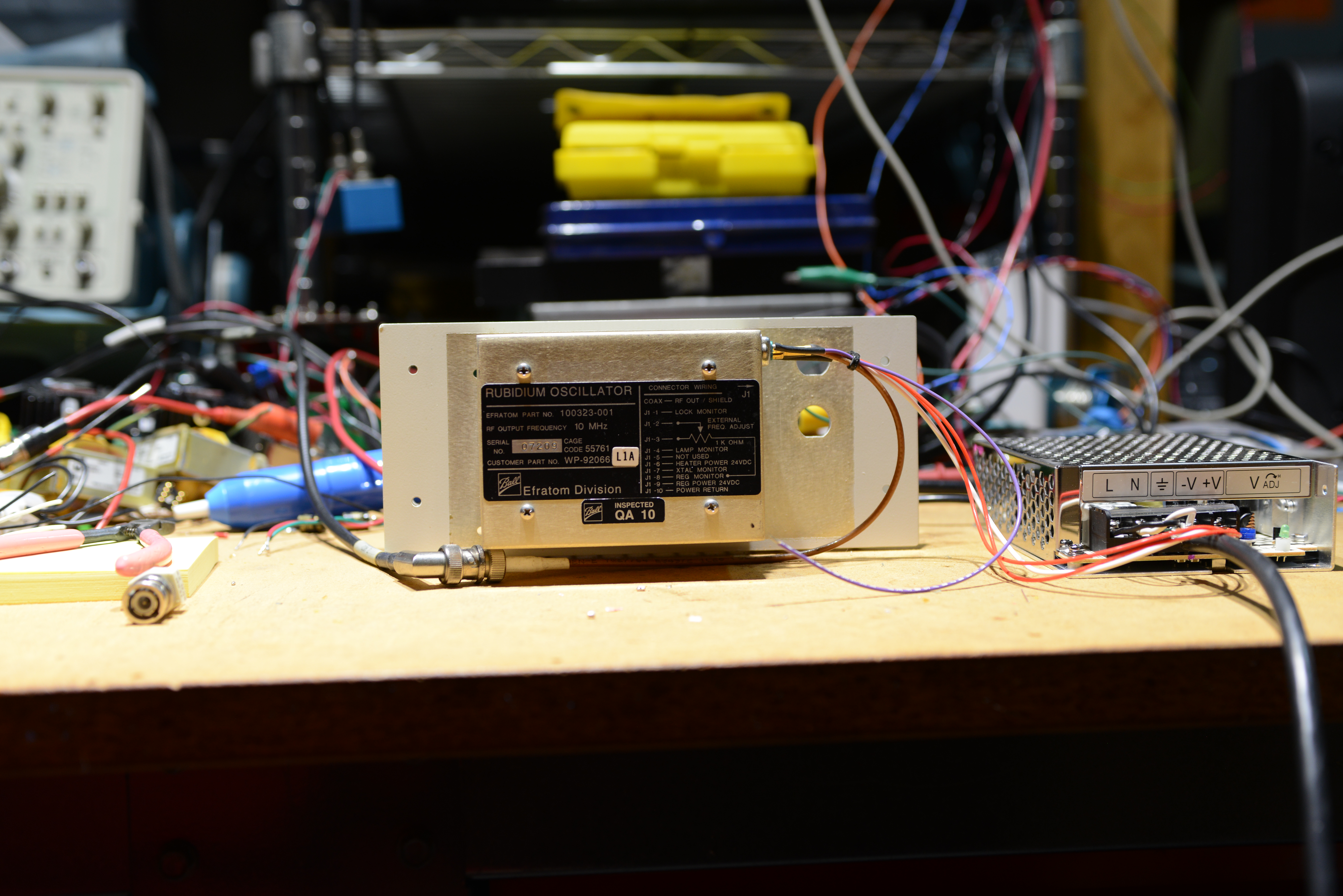
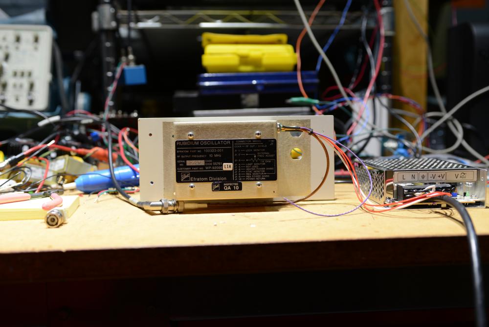
so I bought a bunch of different 10mhz master reference oscillators to see if there was any difference. and yes there is a big difference, this is my favorite. a rubidium disciplined ocxo
-
a true balanced differential amplifier will have significant common mode rejection. For example there are a few well known diy dacs that have a bit of dc on their output. a differential amplifier will subtract the dc from the inputs and the output will be free of dc with respect to ground. a balanced amplifier made from 4 x unbalanced input amplifiers will have significant dc on the output. For headphones wired as balanced, no problem. For headphones wired as single ended, could be a big problem. supersymmetry dynalo and dynahi are true balanced differential amplifiers. So is the RSA darkstar (although it still sounds like shit) schiit joutenheim is a balanced differential amplifier (actually its an instrumentation amplifier) but has significant differential gain when used with a single ended input. liquid gold, liquid carbon, gsx are not balanced differential amplifiers. The first two have phase splitters to fix the problem. the gsx is balanced out only when you have a balanced input signal.
-
for this design the inputs need to be 600v parts. so no jfets. it would need to be cascaded inputs, and change in the input bias to get that to work
-
I will look to see what I have, but the original output transistors are also obsolete would be easy to take ssdynalo board and throw half the parts away
-
6c33 output tube for the win