


Craig Sawyers
High Rollers
-
Joined
-
Last visited
Everything posted by Craig Sawyers
-
And that looks truly spectacular. Looks like the the amp equivalent of a custom car job. MMMM. Inu's powder coated T2 looks great - and his coater managed to get right in to the heatsink fins. I did my KG triode chassis with black crackle finish - which you can get from specialist suppliers of car restoration accessories. Sprays on and looks just like flat black, but as it dries (in the domestic oven - shhh, don't tell - the wife was out...) it crackles.
-
You will note that I actually said "If you are still concerned, you can go over the leads, package entry and PCB pads with a conformal coating pen - a bit like solder resist, apart from the fact that you can solder through this stuff if you need to do a repair" So what precisely is your point? Specifc RTV (Room Temperature Vulcanising) formulations - and there are very many - have an application on very high voltage stuff, or on multi kV voltage multipliers in TV's and oscillosopes, but looks like a pig's breakfast on something like an electrostatic headphone amp. Nail polish is based on a chemical concoction of agressive solvents (like toluene, butyl acetate, ethyl acetate etc), different from one manufacturer to another, that I would let nowhere near circuit board solder resist, let alone passive components, or even semiconductor packages. I also have no idea what it's high voltage insulation properties are - I seriously doubt that anyone has measured it, and the manufacturers for sure won't know. Back when I was 16 I used it for masking simple self-etched circuit boards, but that is about the only electronic use for it IMNSHO. If you are going to insulate package lead outs and PCB pads - which is fine and dandy - , use the correct material for the job - it is called conformal coating - and is available from any decent supplier (Mouser, Farnell, RS components, etc etc etc). Available in a spray can, a can of liquid for use with a spray gun, or as a pen for local application.
-
Great cake. MMM cake. Image shack provided cake, and also offered me an advertising screen offering me shag buddies, and a selection of windows-like pop-ups offering porn downloads. MMM cake.
-
Heavens - lets just knock the whole idea of DIY on the head, why not? After all, what was good for the death of Heathkit ought to be good enough for the death of all the DIY projects on Head Case. Let's get a little perspective here, please! And rely on a seasoned electronics professional like KG to know his stuff.
-
MMM - cake.
-
Creepage and clearance is all to do with product safety. Where the regulations apply is when a hazardous condition can arise through breakdown or shorts - for example around a power transformer, either conventional or switching, or in common-mode inductors in power line filters for example. This is particularly important because power lines are subject to high voltage transients through industrial users, power line fault handling, and environmental disturbance (lightning, solar weather etc). Creepage and clearance has to take these conditions into account. Internal parts in which electrical breakdown does not give rise to an external hazard condition (such as via the chassis, exposed connectors or cabling) are not covered. This thinking is well considered in the European Low Voltage Directive Electrical Safety: Low Voltage Directive (LVD) - Electrical engineering - Enterprise and Industry In any event, the lead spacing between the wide part of the pins on a TO220 varies considerably depending on the device. Specification and caliper measurement on three devices rated at 800-900V have minimum interlead spacing between 1.02mm (0.040") and 1.35mm (0.053"). The highest voltage device, a 2SA4686A with 1200V Vceo, has 1.65mm (0.065"). In fact there is a lot of evidence that semiconductor manufacturers know about all this, and chose a lead frame that takes device voltage handling into account. Air breakdown is 3kV/mm, and so these devices are all comfortably derated, with the absolute maximum device voltage being between a third and a quarter of the air breakdown voltage. If you are still concerned, you can go over the leads, package entry and PCB pads with a conformal coating pen - a bit like solder resist, apart from the fact that you can solder through this stuff if you need to do a repair.
-
Those tubes are 50W handling (so those monoblocks must be the thick end of 100W each). The downside is that the tubes are $2k a pair.
-
The neat thing that I've done in the past in products I've developed (mainly mil stuff) is to have the panel engraved after either powder coating or anodising. The engraving can either be left as it is, or filled with colour - or a range of different colours. Much more robust than silk screening. One of the old timers from Tektronix was telling me the way they developed the lettering for the old tubed 500 series was to have a load of panels done in different ways (engraved and filled, screen printed etc) and stuck them to the floor in Tektronix's entrance hall. Employees were required to walk on them when they passed to pick the most robust. The original choice was engraved and colour filled. They then moved to silk screening once they had a process that also passed the walking test.
-
It sure is. I sent KG a chunk of Lignum Vitae, and he did the business. There are some detailed pics he took before shipping it way back in this thread somewhere. A real source of joy - just waxed it to bring out the grain.
-
Try Permissible RMS Voltage Between the Legs of a TO220 package? for the answer. And your font is small because you used Times New Roman. New Romans must have had good eyesight.
-
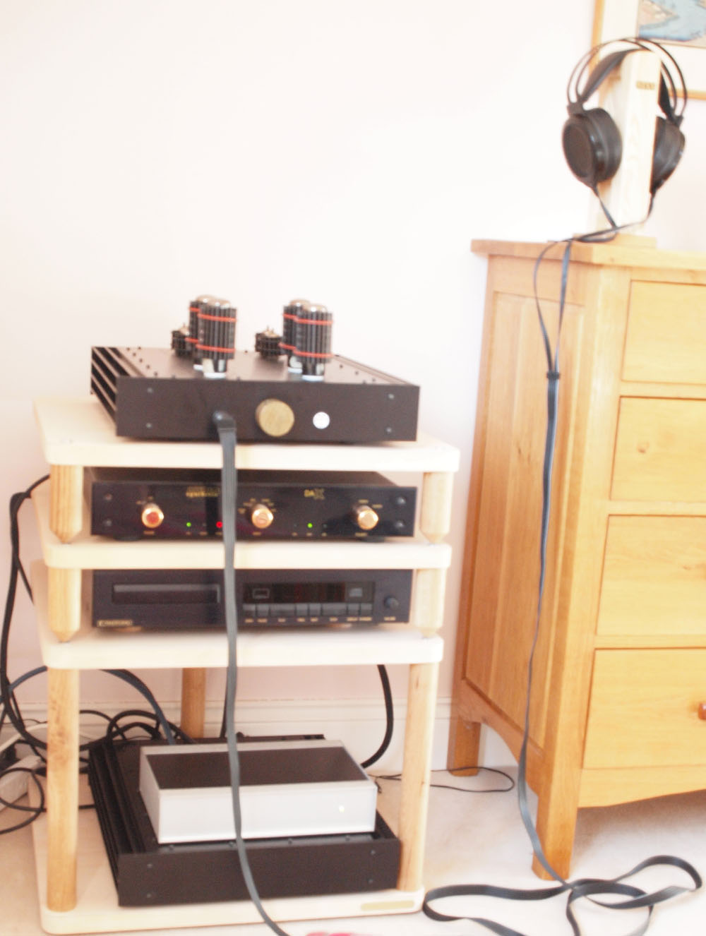
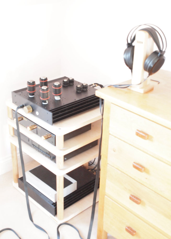
They are Pearl tube coolers. Main aim is to even out and reduce envelope temperature - increases tube life by a factor of two - but they do have a damping effect too. Corrugated and blackened copper held on with high temperature O-rings. Important with four rather expensive Mullard xf4 original EL34's. Got them from Parts Connexion.
-
Here's a couple of pics with the T2 where it lives in the corner of our bedroom (and that was an interesting conversation, trust me ). [ATTACH=CONFIG]4217[/ATTACH] [ATTACH=CONFIG]4216[/ATTACH] Also measured the amp heatsink temperature after 8 hours = 48C (118F). The power supply was quite a bit cooler than that.


-
Well first off - don't believe for one minute that my build of the T2 was without problems! But the shoulder washers wasn't one of them. The only thing to watch is that these are one thou larger in bush diameter than a regular TO220 bush. So they go into some transistors real easy, and in others they are pretty tight (technically an interference fit) - but they do go in with some persuasion - depends on where in the tolerance band the bushes and transistor holes lie.
-
It is the Aavid 7721-3PPSG. Bush length is 3.18mm (1/8"). Wall thickness is 0.36mm (14 thou) and the material is 40% glass filled polyphenylene suphide, which has a dielectric strength of 385V/thou - so 14 thou = 5.4kV. I've used these exclusively on the T2, and we're talking 50 devices mounted to grounded heatsinks this way, without any difficulty.
-
I've never found a plastic screw (and I tried a few different types on my T2 build) that will take anything like the recommended torque for a TO220 (around 1.1Nm, 8-10 inlb). The best reference for semiconductor mounting I've come across is Onsemi's AN1040D http://www.onsemi.com/pub/Collateral/AN1040-D.PDF . I ended up with a long Aavid bush that went most of the way through the 2mm alumina insulator, and then used steel fastenings.
-
Whatever you do, ask them about masking the areas where the fixing bolts go so all the chassis components electrically connect together. You really need that for safety, and at the very least not to feel that tell-tale tingling feeling when you touch a floating piece of chassis. You *can* remove the coating where the screws are afterwards (Dremel), but any coating worth a damn is tough, and this is a pain in the ass given how many fixing bolts there are. They may ask you to do this, in which case you need to find out what sort of tape they recommend to do the masking. I discovered this gotcha decades ago after I bought a second had copper vapour laser (at work). All the laser head chassis components were thick powder coated, and not electrically connected. There was so much high power interference getting out the chassis seams that I got an rf burn. I was not impressed.
-
Yup. Solid rules those Yeah - I had a couple. Which weren't really enough for setting up a T2, so I went on an eBay raid. So now got 4 8060A's, an 8024B and an 87V. Put 1mm jacks on the test points on the tube side of the board and made up some 4mm to 1mm test leads. So I can set the batteries up by just taking the top plate off and plugging straight in. Put a ground wire on the board so another pair of meters go from ground to the stax jack. Switching those between DC and AC allows the noise voltage to be measured durning final battery tweaking.Interesting comment, Inu. Could you expand on that please?Here's something interesting. The BH seems to take quite a while after turning on to come on song - around an hour or maybe more. But the T2 wakes up very fast - a minute or two after the HT relay clicks in and it struts its stuff. Have any of the others with completed beasts noticed this?That is a classic. If you haven't done that at least once, you haven't lived! Depending on the Fluke, you are likely only to have fried the input protection. There are a couple standard fuses, a couple of fusible resistors (which you have to get from Fluke), four thermistors (cheap standard parts) and some transistors wired as diodes. Some or all may have gone to heaven. You can tell from the way I rattled that off without looking at a schematic that I've been where you are now. The lesson I've learnt the hard way on several occasions is don't test stuff when tired.Result! Happened twice to me, once with a pen and once with an HP calculator. Bought replacements - at which point the original escaped from the bowels of the cabin. I'm sure there are black holes whose purpose is to screw with your mind. It is where all my odd socks and allen keys go.I haven't read any Lovecraft for a very long time. That is my wake up call to read or re-read a few of his very disturbing books.Yes - A bit like Hichhiker's Guide "Every time I press one of these black controls, labelled in black on a black background, a little black light lights up black to let me know I've done it. " The only relief is the glow of the tubes and the awesome lignum vitae knobJust for the record, there were three mods to the power supply and amp: (1) The power supply mod developed by Kevin and Inu to make it stable (2) Adding precautionary 750 ohm resistors in series with the gates of all K216's (3) Adding 5pF 1kV caps (I used ceramic, Inu used mica) across the 100k feedback resistors. That was also an Inu mod. (1) and (3) are essential IMHO. (2) is discretionary - these resistors were not present in the original from examination of the photos. It has already been said - this sucker runs real hot. Once it has been on for a few hours the heatsinks, front panel and top plate are toasty.

Important Information
By using this site, you agree to our Terms of Use.