JoaMat
-
Posts
1,549 -
Joined
-
Last visited
-
Days Won
16
Content Type
Profiles
Forums
Events
Everything posted by JoaMat
-

and now for something completely different part 3
JoaMat replied to kevin gilmore's topic in Do It Yourself
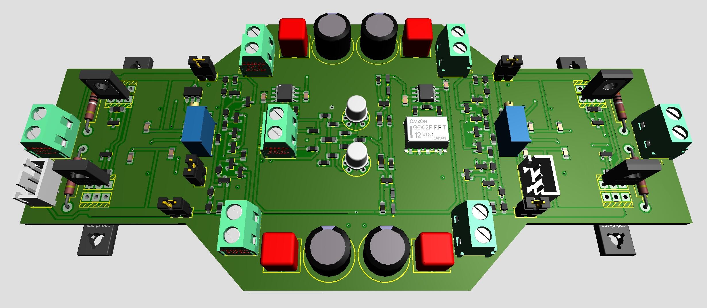
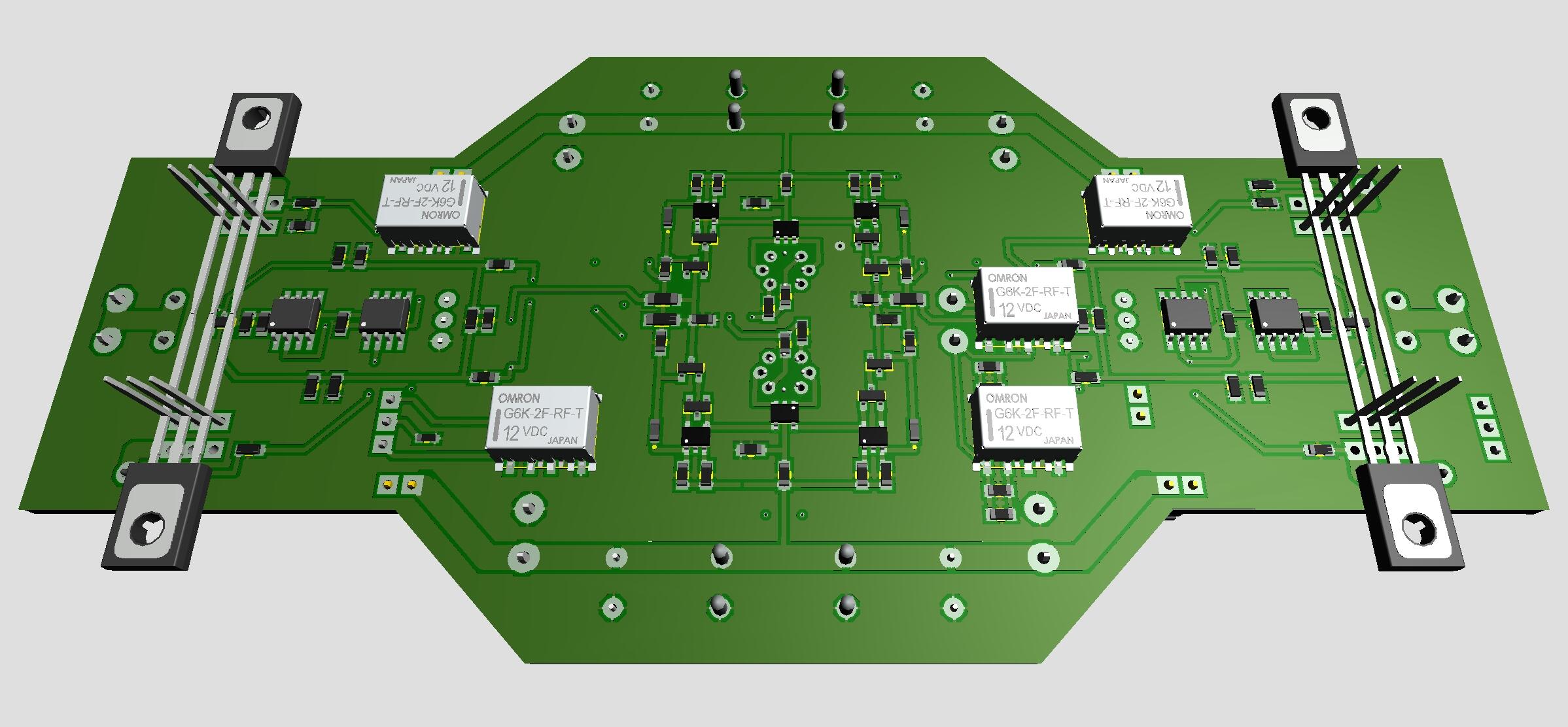
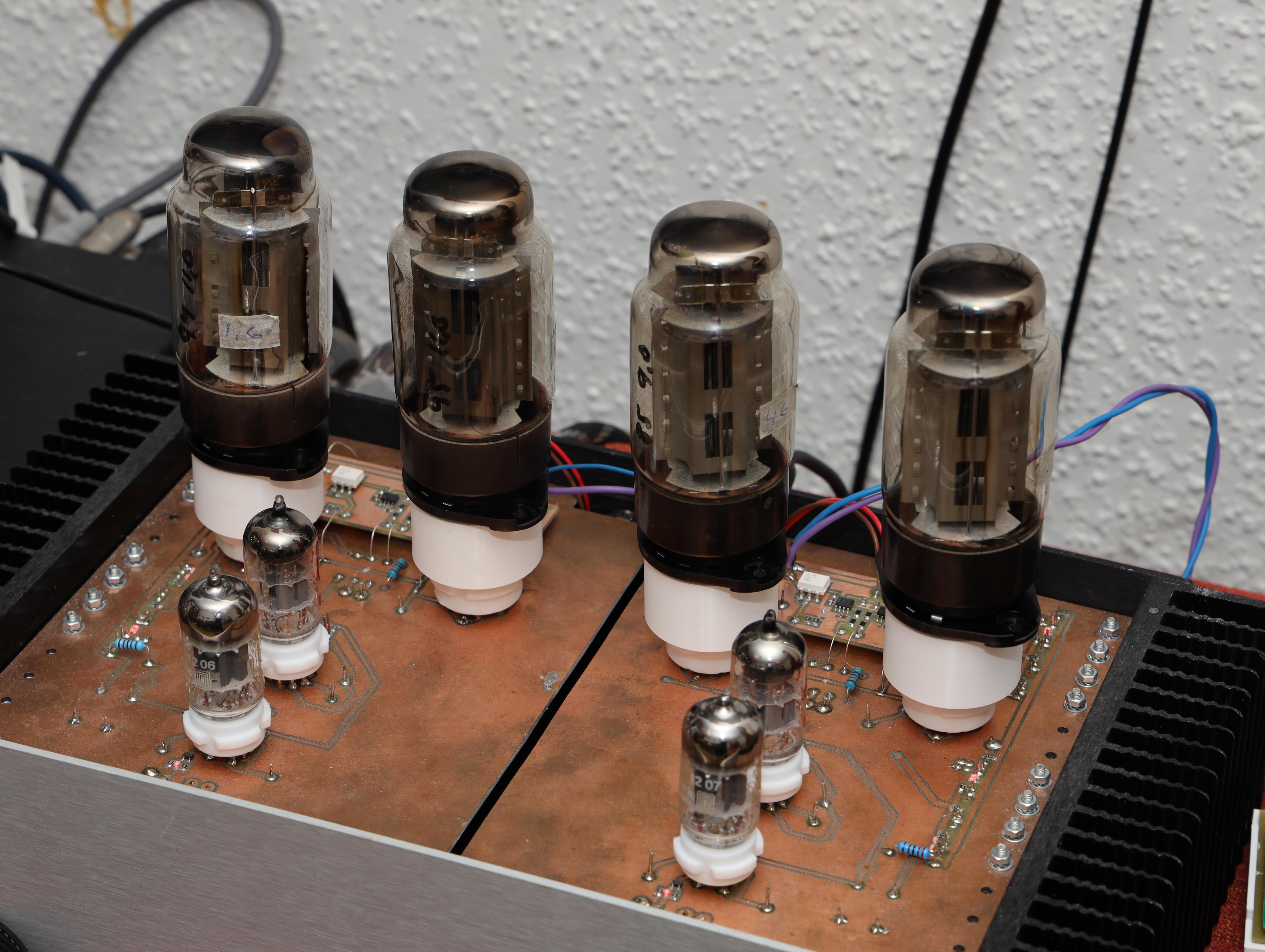
After another week of testing I like the outcome of the latest CFA3smd something with the dual opamp bias servos. Thanks a lot Kevin. My version is a Zero Feedback version of CFA3. I’ve heard, read, that some people favor the Super Symmetrical version. So, here is a drawing drafting of a ZF/SS version of CFA3smd something with… … six small Omron latching relays. Five for ZF/SS switching and the sixth for LED identification of mode in progress. Two JST XH3 connectors for a momentary toggle switch and LEDs to control the ZF/SS modes.
-
and now for something completely different part 3
JoaMat replied to kevin gilmore's topic in Do It Yourself
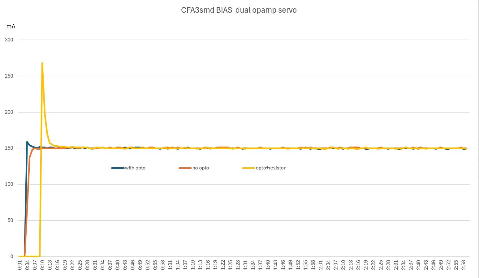
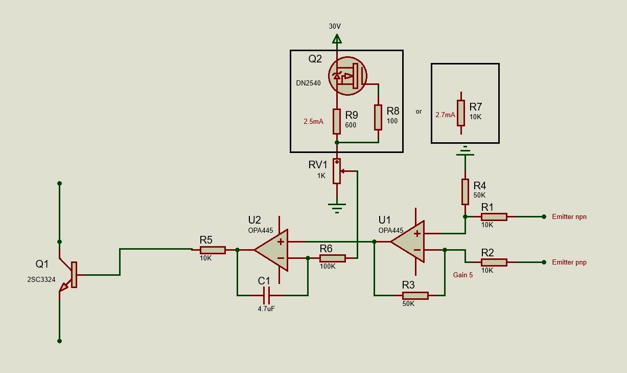
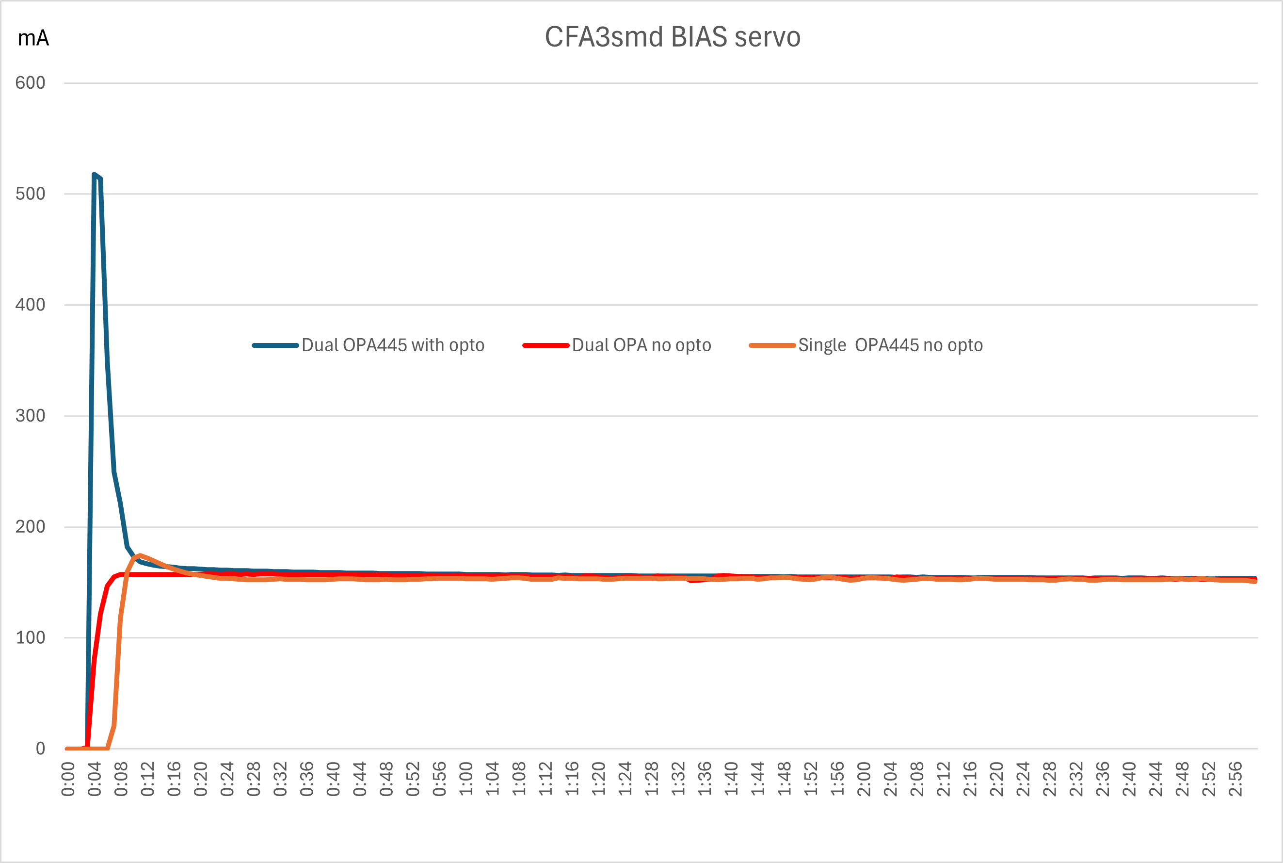
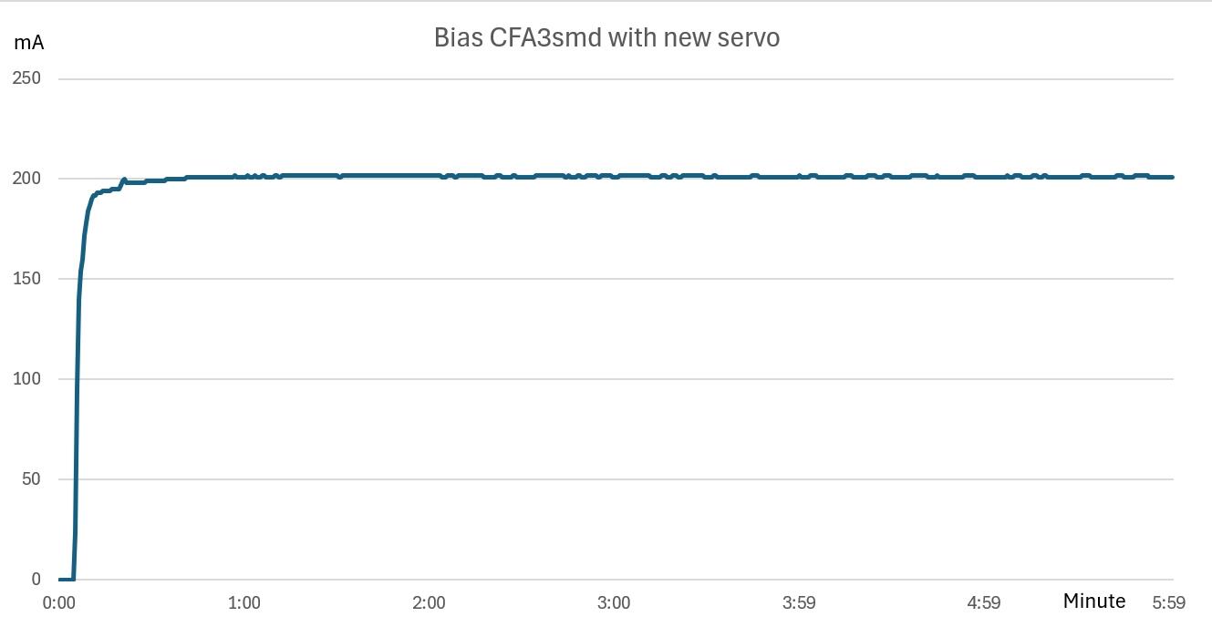
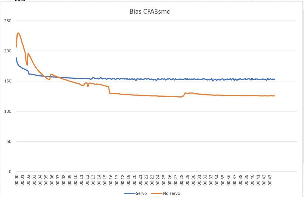
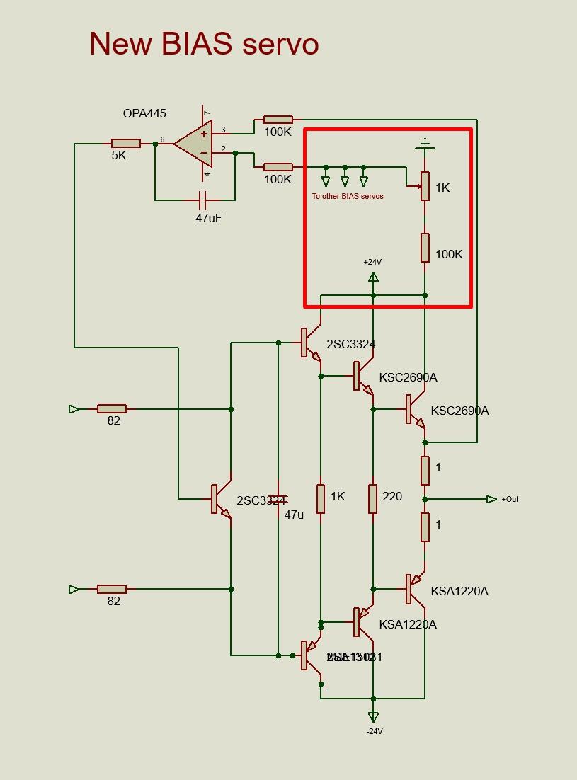
Yes, dual opamp seems to be the way to go. Only changes to the old board are added opa445, opto coupler and three resistors to each bias servo. All operating point unchanged. So, I didn’t follow Kevin’s suggested servo in full. Now the new CFA3smd has been in service a week and I’ve made a few changes to the servos. Increased gain of opamp, increased current through the bias set trimmer and omitted opto coupler. Diagram shows the behavior for servo with and without opto coupler. I also added 7K and 1K resistors (to simulate R36 and RV2, see Kevin’s schematics) and got the yellow (opto+resistor) curve. Schematic showing the final (for now) servo.
-
Happy Birthday!
-
and now for something completely different part 3
JoaMat replied to kevin gilmore's topic in Do It Yourself
I’ve just finished an updated version of my CFA3smd something. Main difference is dual OPA445 bias servo with optocoupler as Kevin suggested previously in this thread.. Diagram of bias behavior from cold and the first 3 minutes. With optocoupler there is an overshoot before stabilizing at desired 150 mA. Removing optocoupler gives a nice take-of and climb to 150 mA. The diagram also shows the old single OPA445 servo with no optocoupler. It takes some more seconds before start climbing compared to dual OPA445 and a small overshoot before stabilizing.
-
Happy Birthday!
-
Megatron Electrostatic Headphone Amplifier
JoaMat replied to kevin gilmore's topic in Do It Yourself
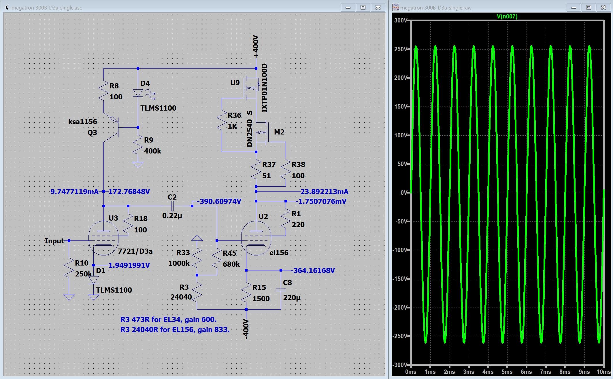
Someone told me D3a is a good tube, Did this in LTspice… Modified Megatron – one less capacitor in signal path and no feedback. Works in LTspice. That's always something.
-
and now for something completely different part 3
JoaMat replied to kevin gilmore's topic in Do It Yourself
No particular reason behind the jfets, aside I like the to-71 package and that it’s fairly easy to build the layout around them SMD transistors because they are small. I had to decrease current at some locations to reduce heat. I see this amplifier merely as an experiment. I wanted to test if it was possible to make a small board. The bias servo is probably needed while moving from heatsinked MJExxx to small smd transistors. I believe the bias servo previously posted by Kevin, with dual op amps, is preferred. So, another experimental board…
-
and now for something completely different part 3
JoaMat replied to kevin gilmore's topic in Do It Yourself
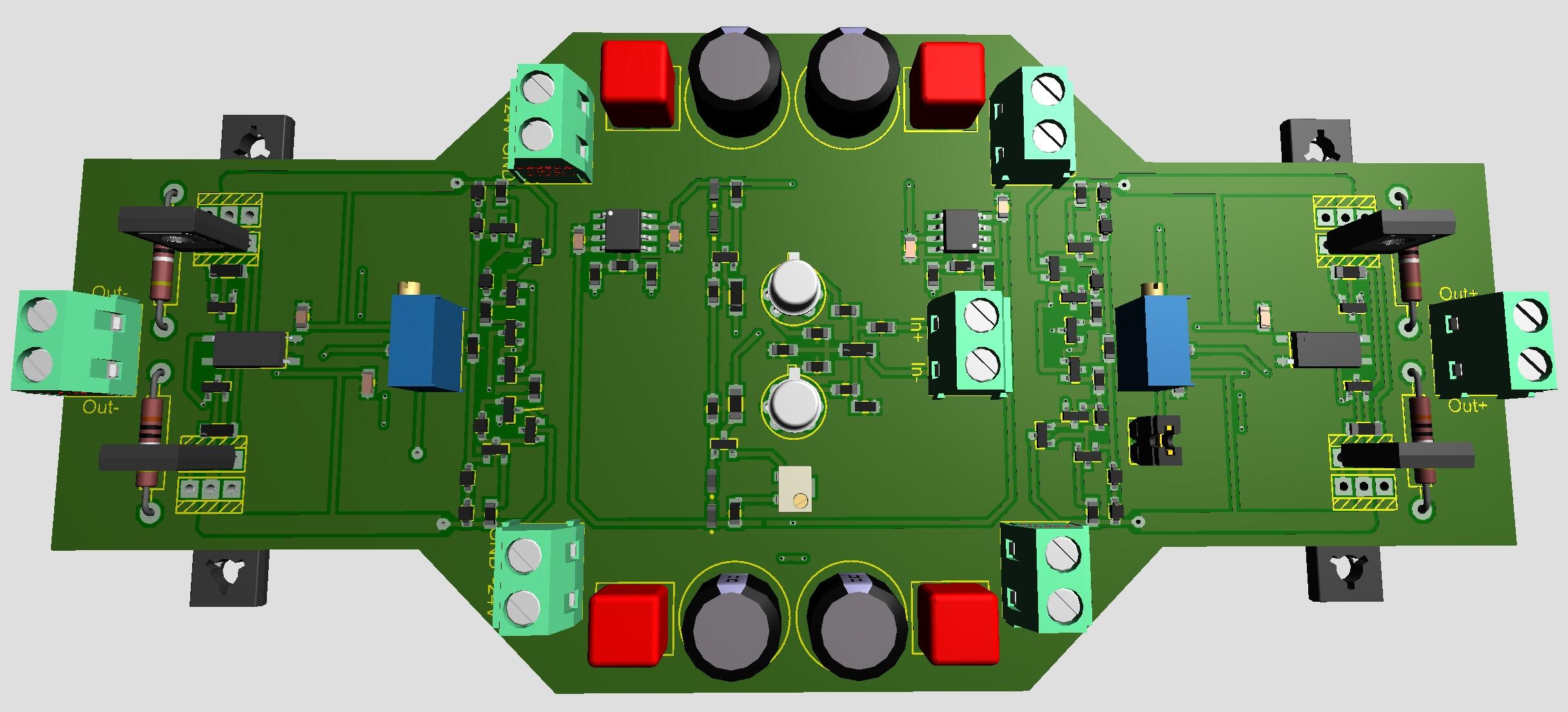
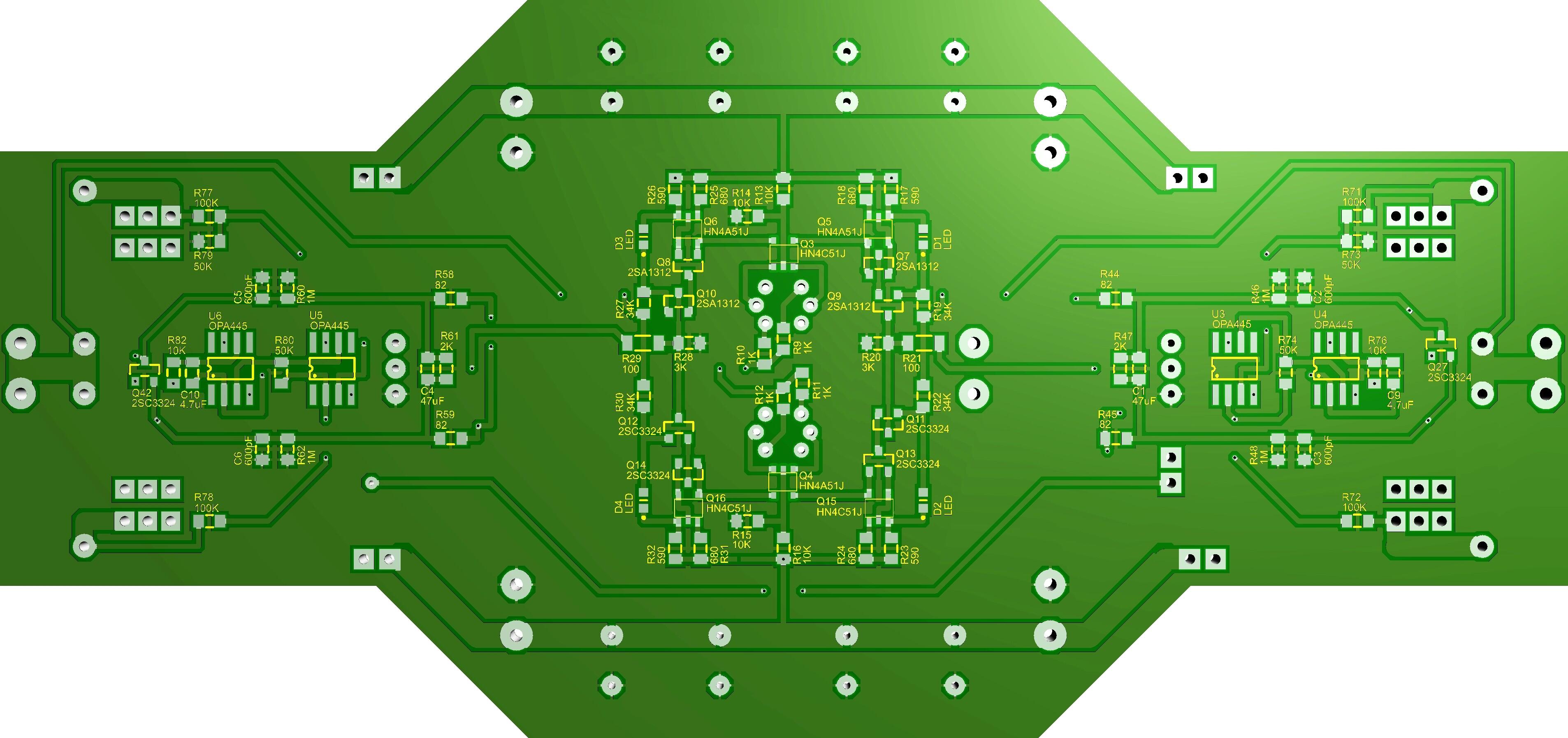
Attached ZIP-file with gerbers, shematics and some 3D views. CFA3smd.zip I’ve used both gerbers when I milled the boards (kitchen made) and that is about three years ago. Board size 160mm x 74mm to fit on Modushop 200mm x 80mm heat sinks. Take a look at the files and see if/how the boards could be a part of your project. I think one should make a few changes to attached gerbers before considering sending them to a fab house. -
Megatron Electrostatic Headphone Amplifier
JoaMat replied to kevin gilmore's topic in Do It Yourself
I tie cathode direct to -HV, -400 V in my case. Works with EL34, 300B, 2A3, EML 20B-V4 and EL156. The datasheet for my Electro-Harmonix 2A3EH Gold says 450 V maximum plate voltage. -
Megatron Electrostatic Headphone Amplifier
JoaMat replied to kevin gilmore's topic in Do It Yourself
Higher gain and in my opinion better frequency response. I haven’t tried other than the 100uF electrolytics. With the capacitors the amplifier is an absolute favorite. -
Happy Birthday!
-
Megatron Electrostatic Headphone Amplifier
JoaMat replied to kevin gilmore's topic in Do It Yourself
I put 100uF/16V electrolytics in those positions in my Megatron with solid state CCS. I think it made a big difference. -
Happy belated Birthday!
-
Thank you everyone. Had a nice one with my wife in our summer(winter)cottage. Now I’m preparing for Boxing Day +6. Birthday of both our children and one grandchild. Happy New Year everyone!
-
Happy Birthday!
-
Megatron Electrostatic Headphone Amplifier
JoaMat replied to kevin gilmore's topic in Do It Yourself
A frendly Head-Caser has kindly lent me four EL156, So, I made myself some EL156 to EL34 adaptors. Here a Megatron SS CCD something with the four EL156. Same friendly fellow has built himself a couple of filament supply for DHT similar to the one in above post.
-
and now for something completely different part 3
JoaMat replied to kevin gilmore's topic in Do It Yourself
Perhaps you are right, but that’s nothing I can verify. It’s correct that pos input is dancing. Now I think that the neg input is a perfect dancing partner which results in a working servo. With the servo the amplifier behaves similar to the ones without servo except that the bias doesn’t drift. And cross talk? Not a problem - I’m married and used to cross talk. -
and now for something completely different part 3
JoaMat replied to kevin gilmore's topic in Do It Yourself
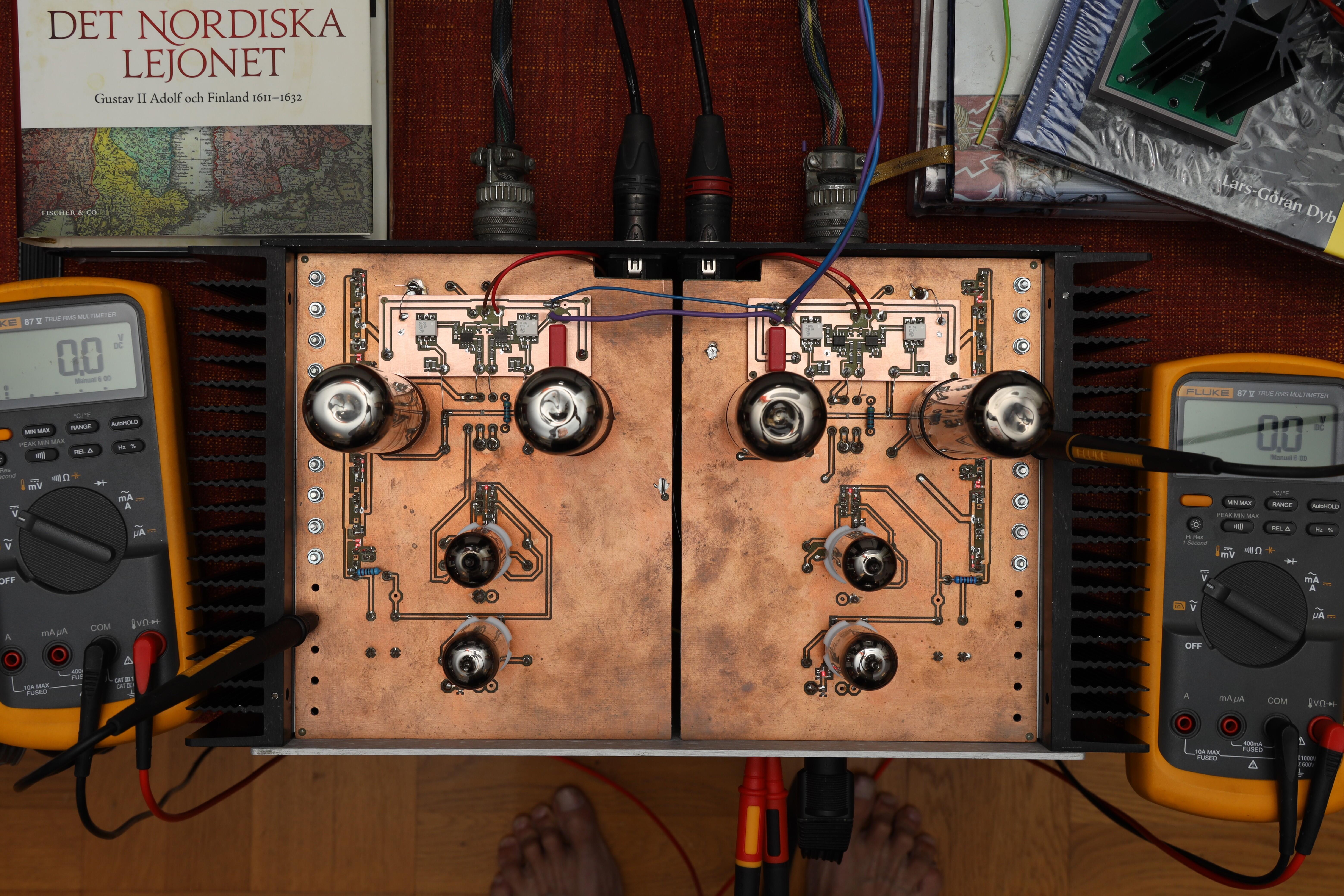
I’ve a smd version of CFA3. Only output transistors on heat sink. Bias is servo controlled. Works all right. Output stage with servo looks like this…
-
Megatron Electrostatic Headphone Amplifier
JoaMat replied to kevin gilmore's topic in Do It Yourself
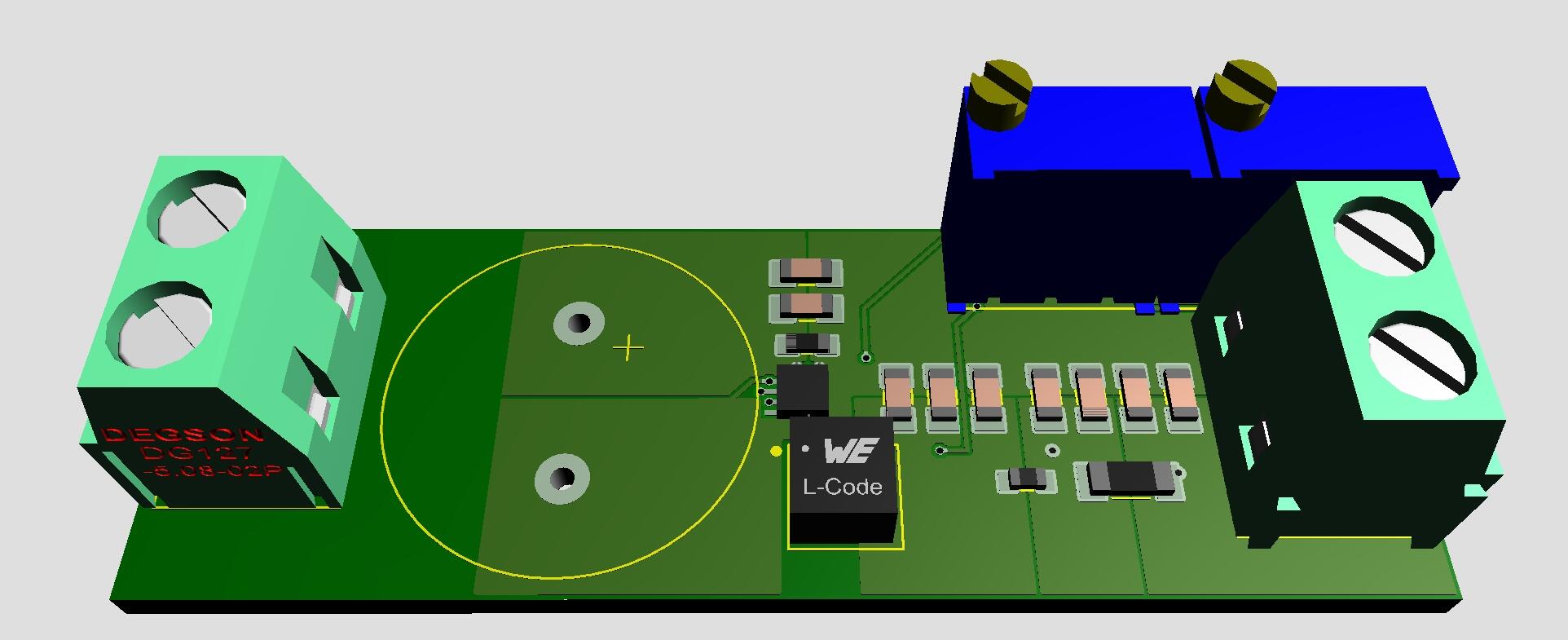
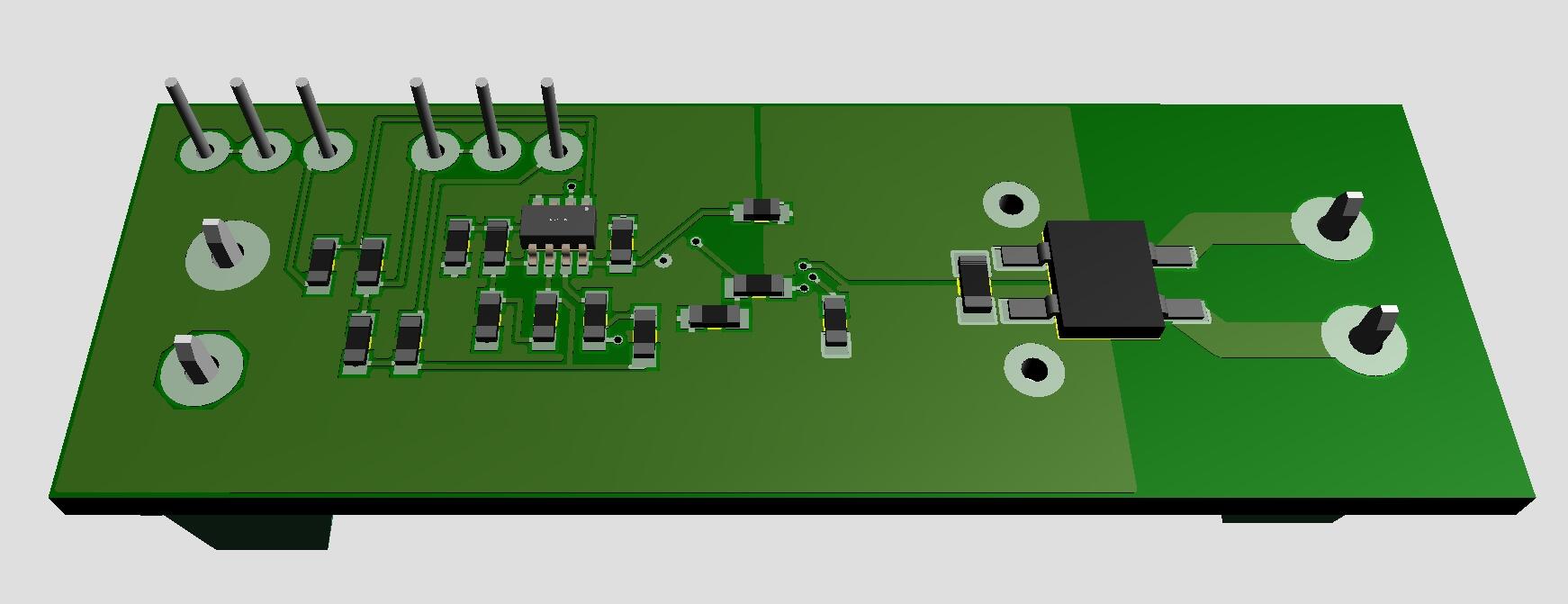
Only in fantasy world... Filament supply for DHT. 9VAC in and 2.5/5.0VDC out. Size 2.07in x 0.7in. All you need is to connect a transformer and a tube to heat.
-
Megatron Electrostatic Headphone Amplifier
JoaMat replied to kevin gilmore's topic in Do It Yourself
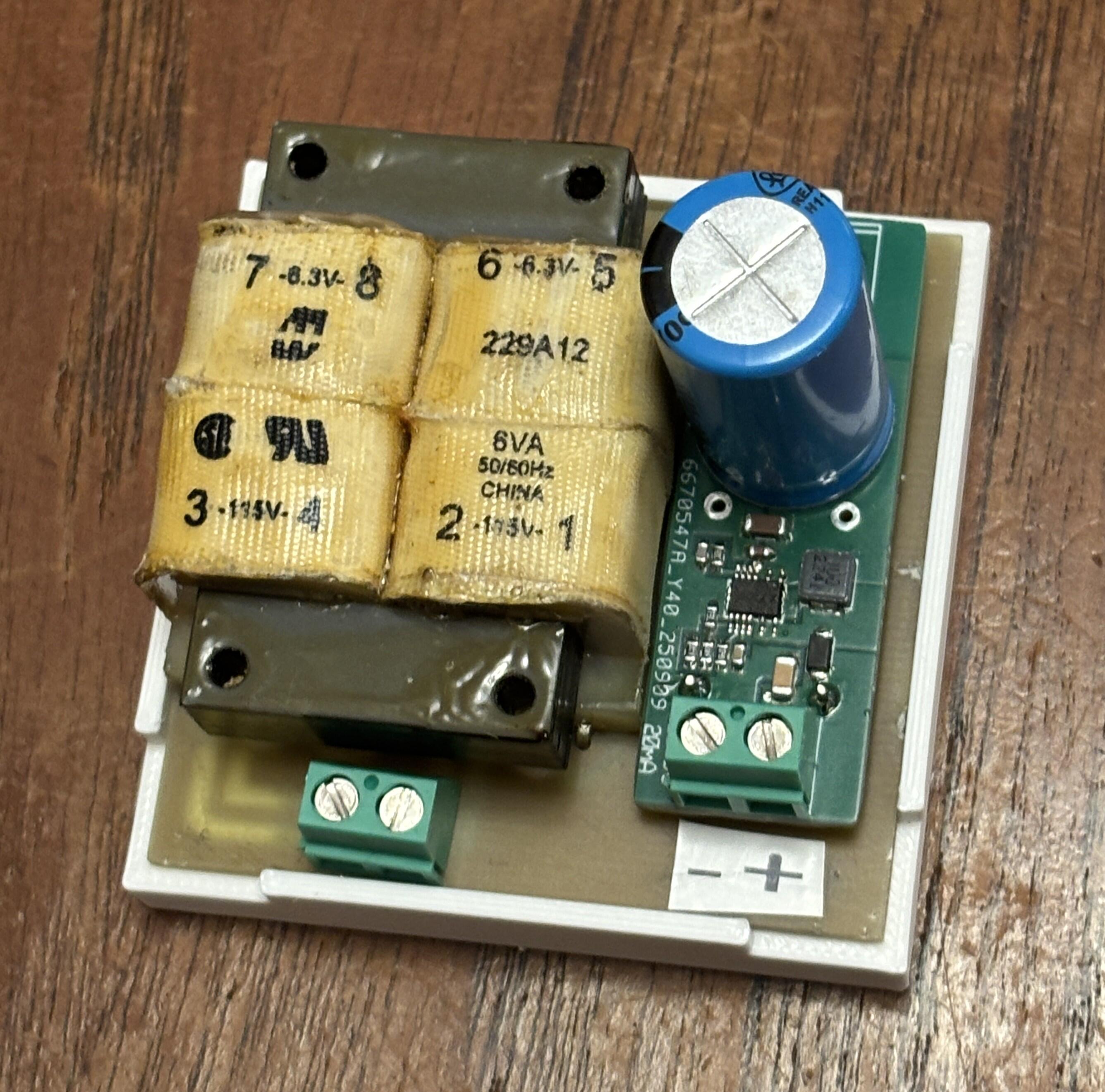
A small 120 V supply for above grid voltage control. 6.3VAC Hammond 229A transformer and LT8365 DC/DC converter. Out 120V . Size 2.3in x 2.3in.
-
Seems simmconn reads shematics. Regarding Q12, schematics and gerbers don't match, I think.
-
Megatron Electrostatic Headphone Amplifier
JoaMat replied to kevin gilmore's topic in Do It Yourself
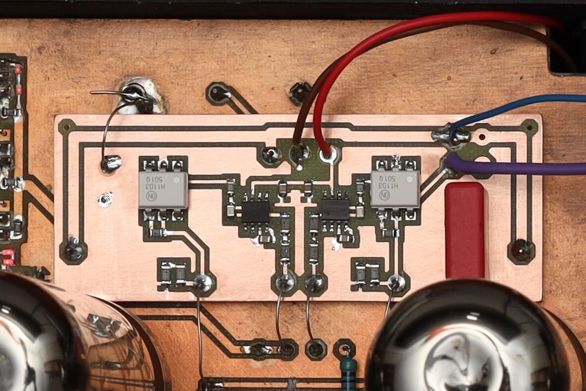
Completed servo controlled grid voltage. Works with EL34, 2A3, 300B and EML 20B-V4.