JoaMat
High Rollers
-
Joined
-
Last visited
Everything posted by JoaMat
-
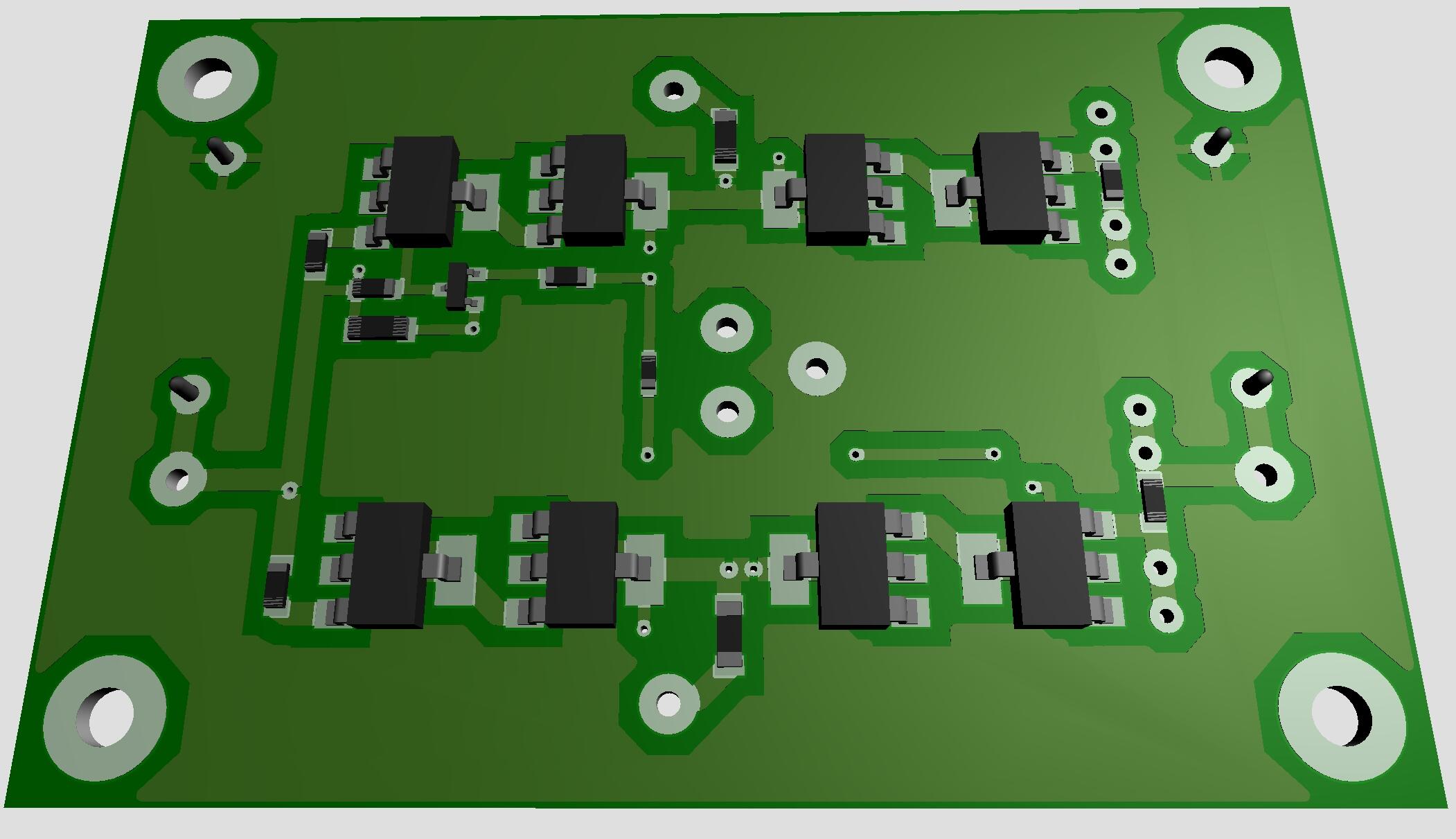
Nice, great news! Did this in 2019 and it has been in sleep mode since then. Maybe UHV-POWER bricks will wake it up. Power transistors plus a few other components on one side and the rest on the other side.

-
-
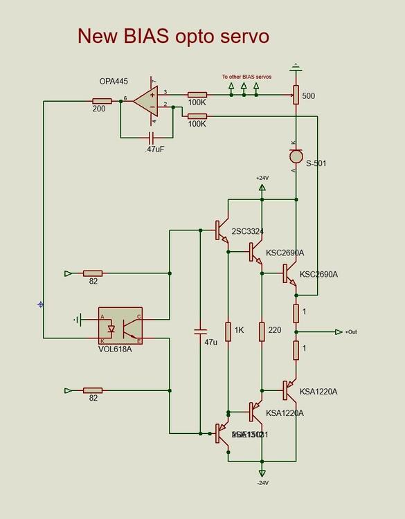
Like this? Think I got inputs to op amp right.
-
-
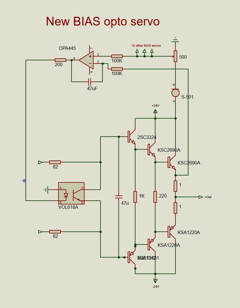
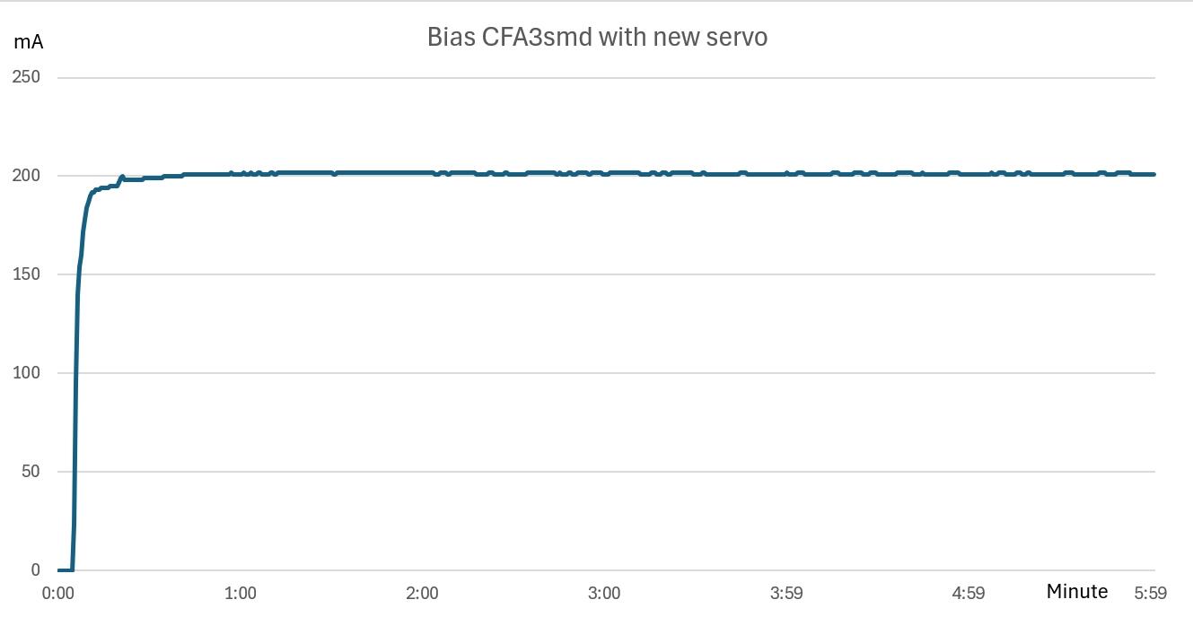
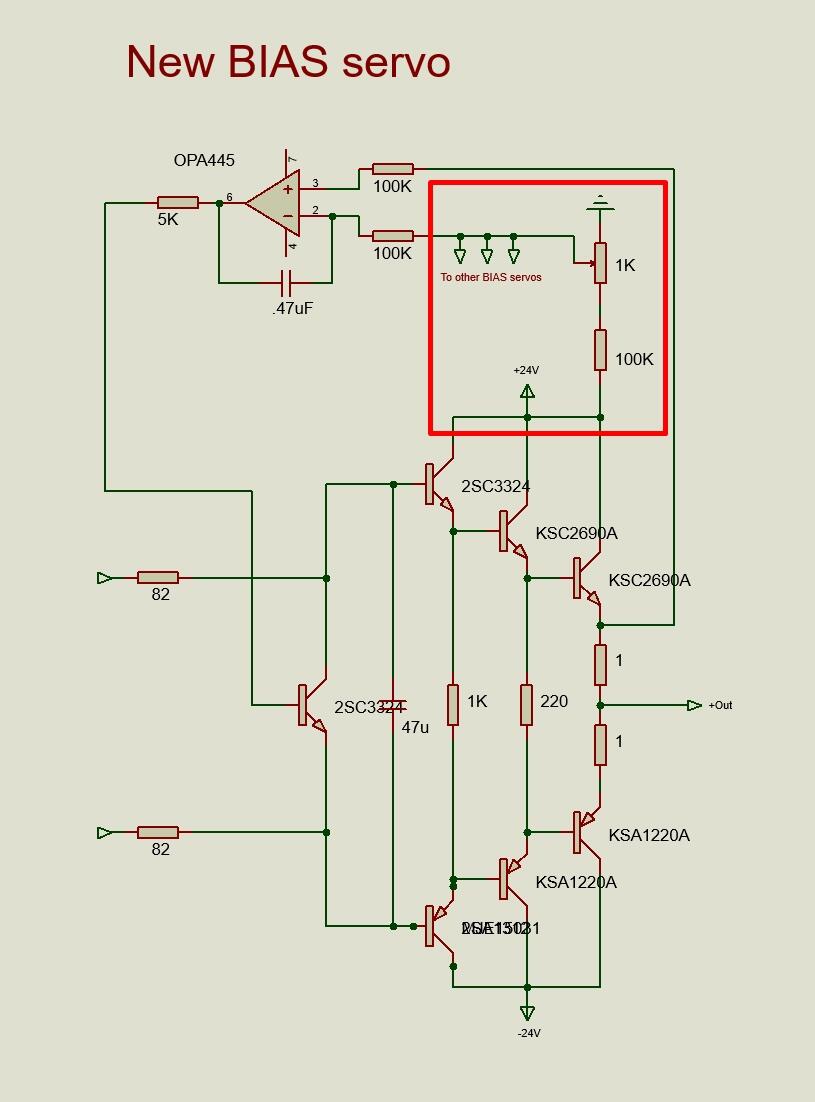
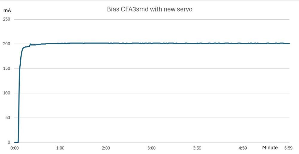
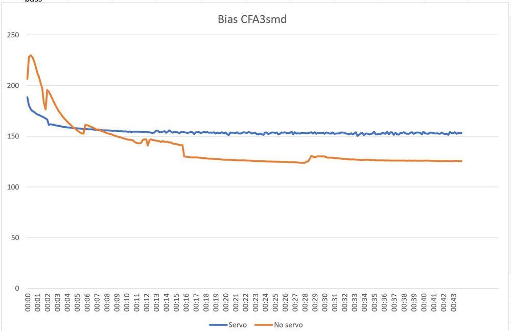
Have had a new bias servo working with my CFA3smd something for a few days. Schematically it looks like this, and the new thing is in red square. Now I get a good reference point to the servos. Don’t understand why I didn’t figure this out earlier – slow brain perhaps. All four servos are fed from the same point. So, one trimmer and full control over the BIAS of all channels. Diagram for new servo - 6 minutes from cold. and diagram for old servo (in mA for the first 40 minutes from power on) Please have in mind that the graph for no servo is for my CFAsmd something. I guess the original CFA3 have a different and better behavior – where all tripple Darlington and vbe transistors are mounted on heat sink.

-
What dual op amp are you using?
-
happy Birthday!
-
Happy Birthday!!!
-
Happy Birthday, Kerry!
-
Great work - more Sort Guld.
-
Emission Labs 20B and 300B, is that the 4 pins socket or the octal socket with center tap filament?
-
-
Impressive! What kind of tool do you use for threading?
-
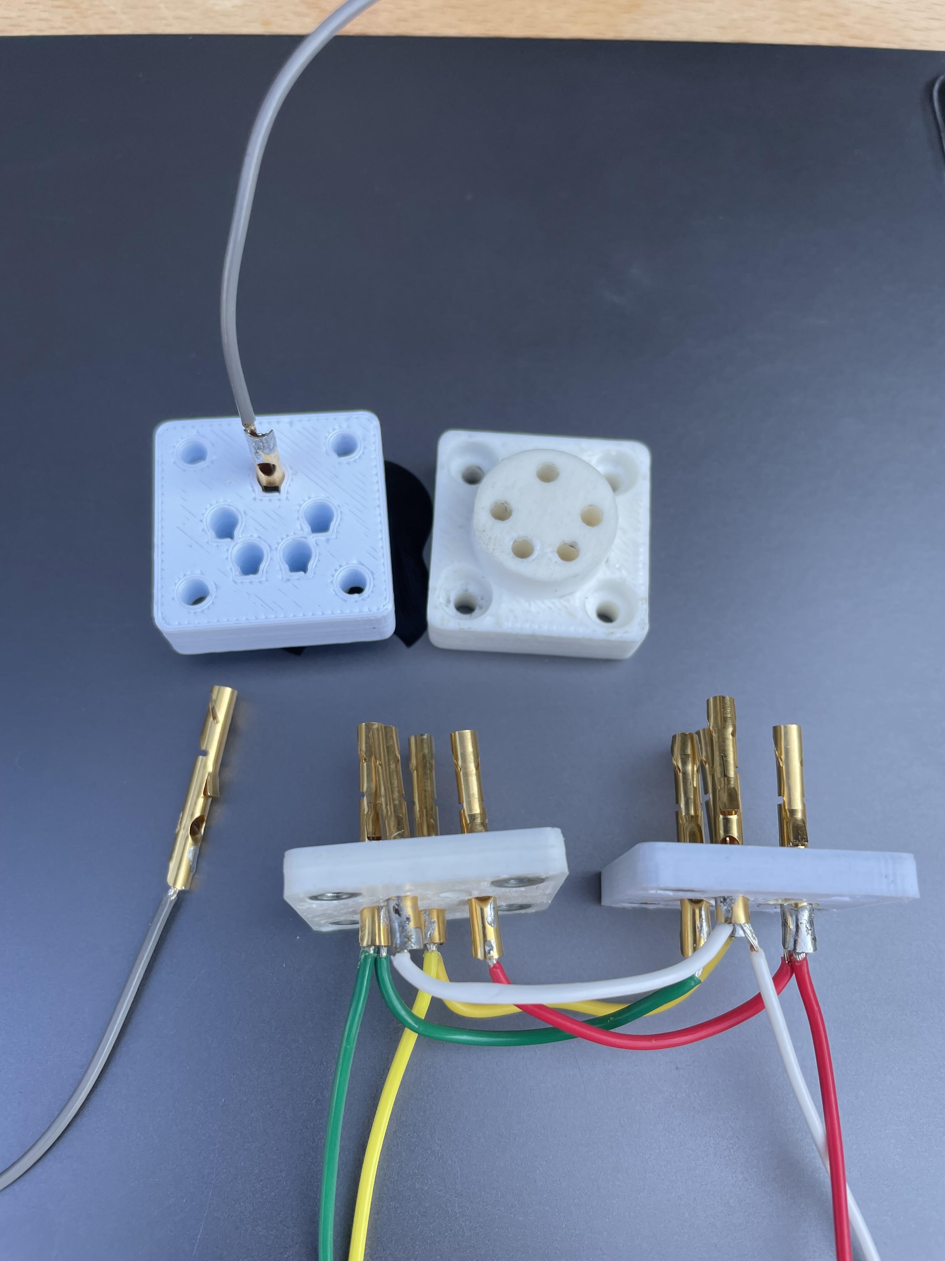
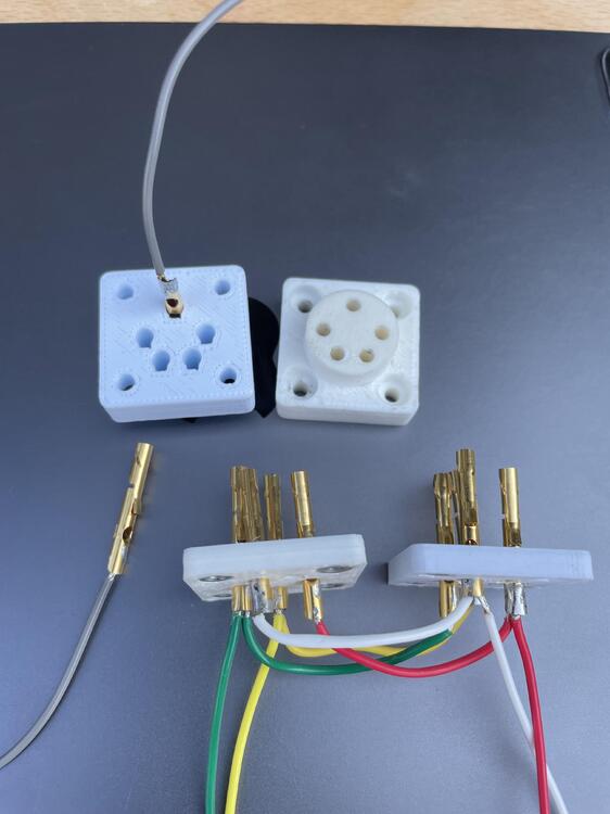
All you need is a forgiving connector. Homemade, 3D printed, socket with “floating” Neutrik pins from NC3FD.
-
-
-
Happy Birthday!
-
-
-
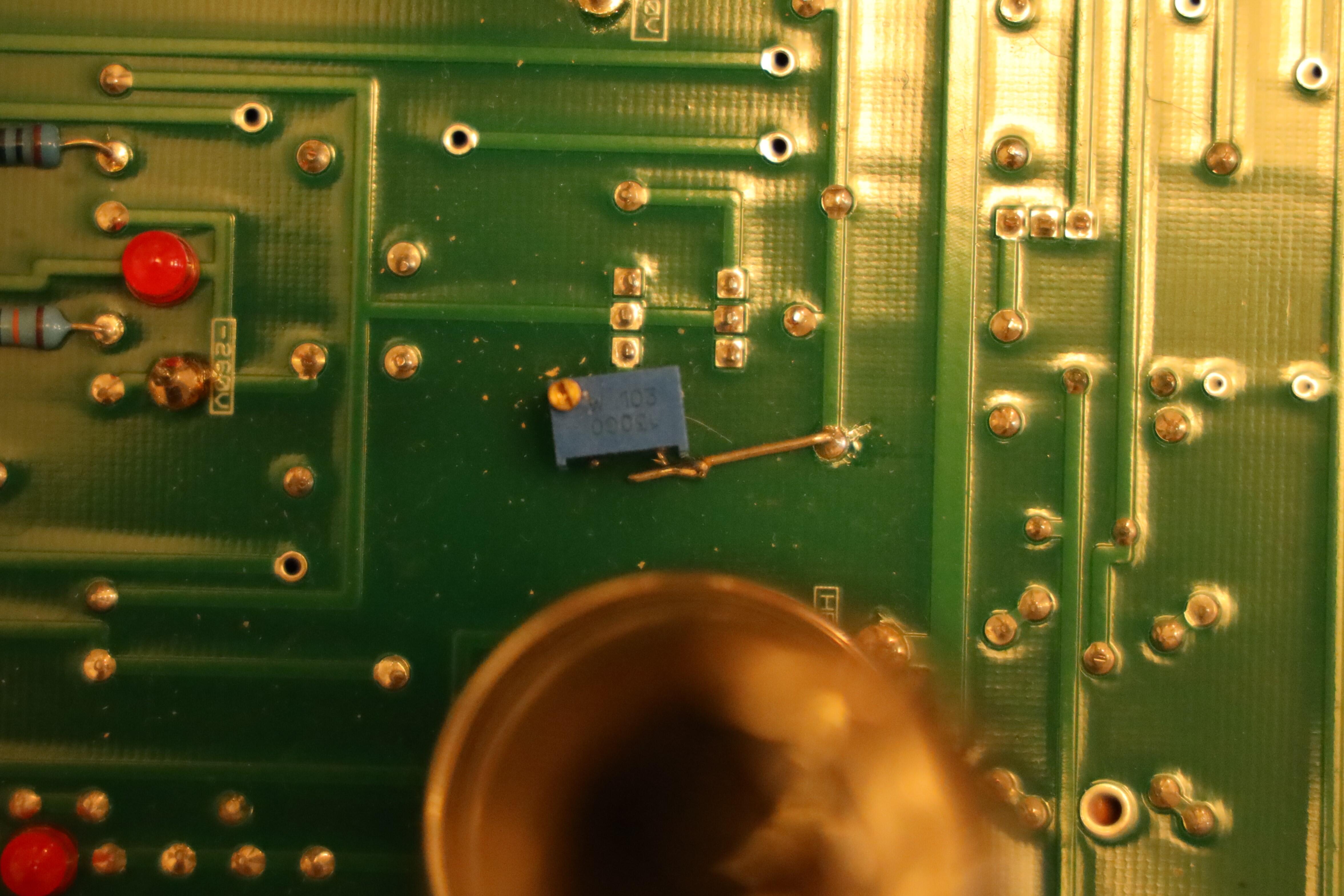
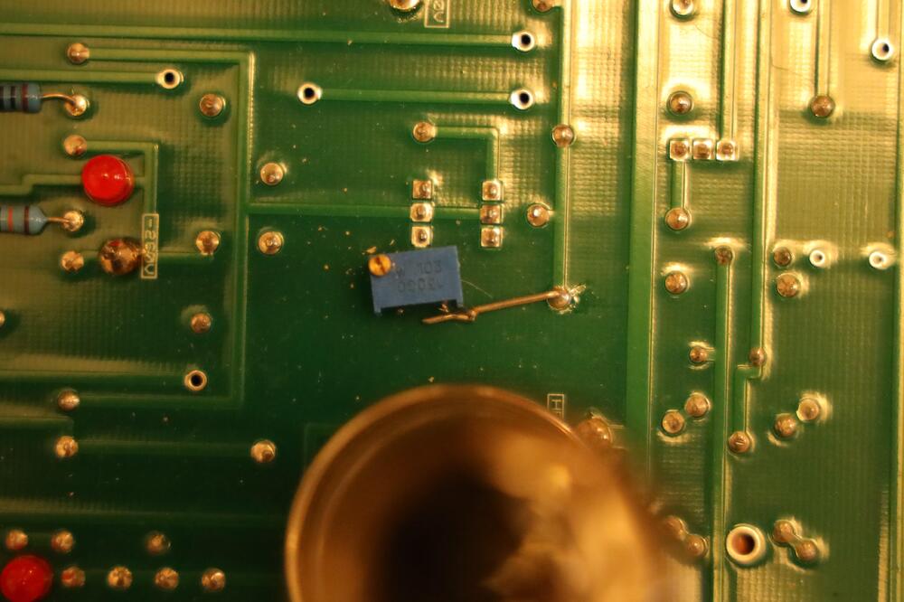
A simple way to adjust offset is to replace R73 with a 10K trimmer. Looks like this on my amplifier. Works like a charm.
-
Seems your balance servos are working since C and D have same readings. As for right channel where you have unbalance – investigate the R88 – R91, C8 and C9.
-
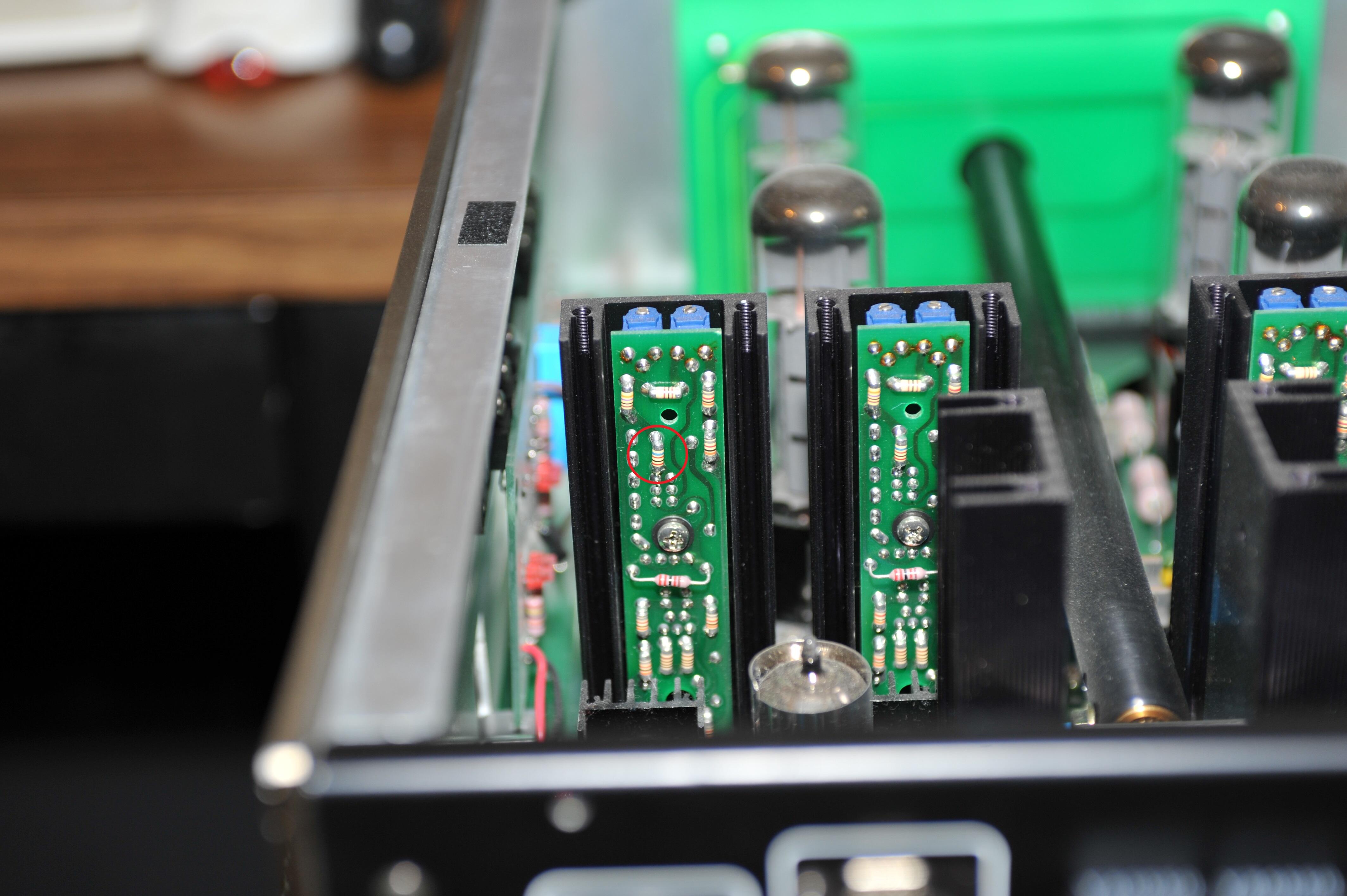
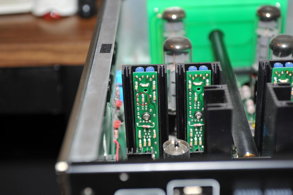
Good point, indeed. Here is a picture I saved on my computer years ago. I don't know the source. Resistor in red circle, is that the 62K one? Zoom in and you get a good view.
-
When things work as they should Q16 and Q17 have the same potential. The string R31+R32+RV1+R33+R34 determines the battery voltage. 6.55V cross R31+R32 gives 6.55V * 1655.8K / 13.8K = 785.9V.
-
6.55V cross R42 and RV1 to R32 side will (in theory) give you a battery voltage of 786V. You have 781V. Why then change RV2 and the 6.55V? Why not reduce battery voltage with RV1?
-
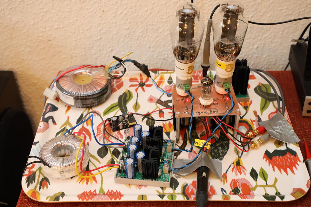
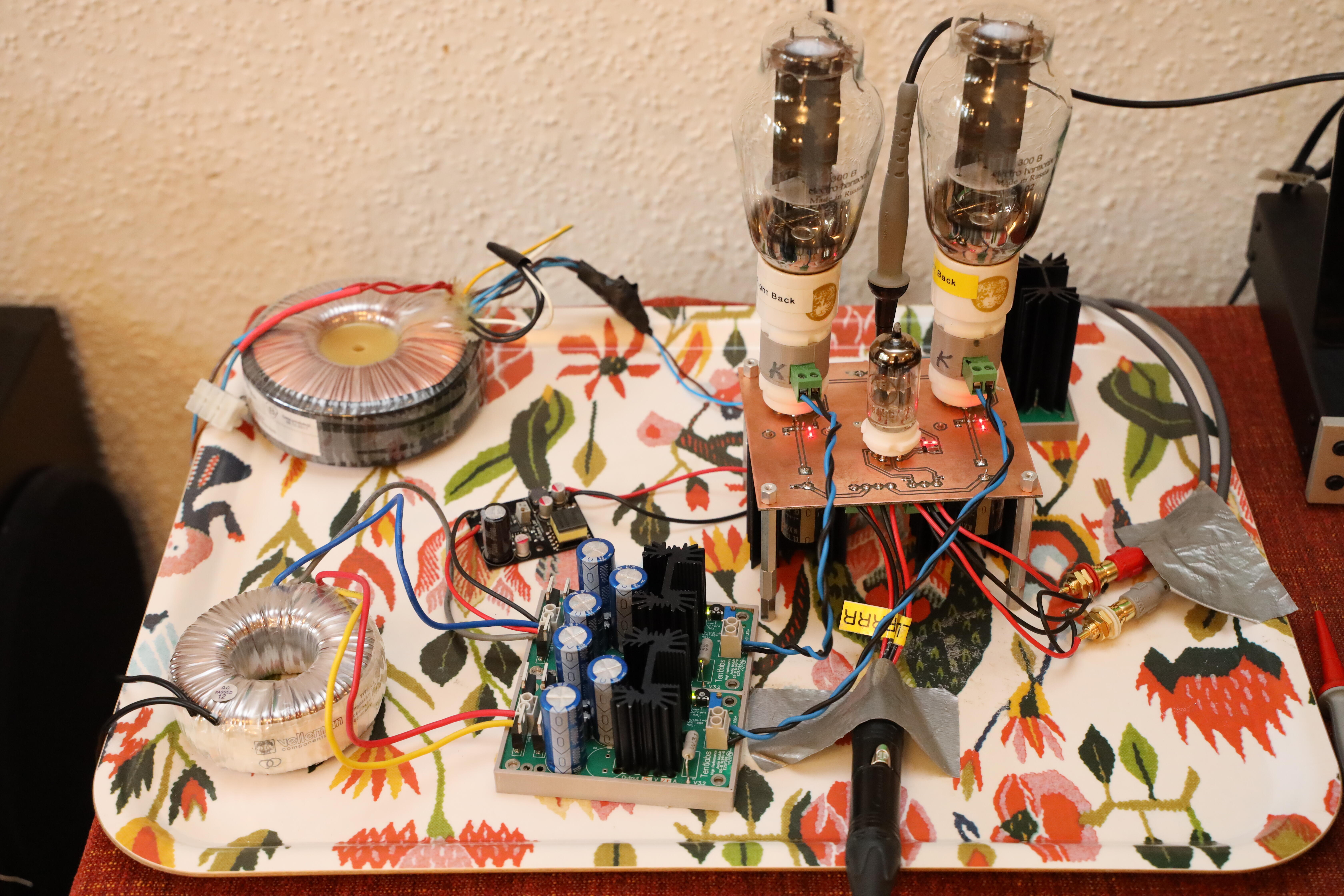
JadeDubbleBottle is served. One 6922, two 300B and a few components on amp pcb. All DC filaments and GRHV at 140V. No cats and children have moved out so, no rush with chassis.