JoaMat
High Rollers
-
Joined
-
Last visited
Everything posted by JoaMat
-
-
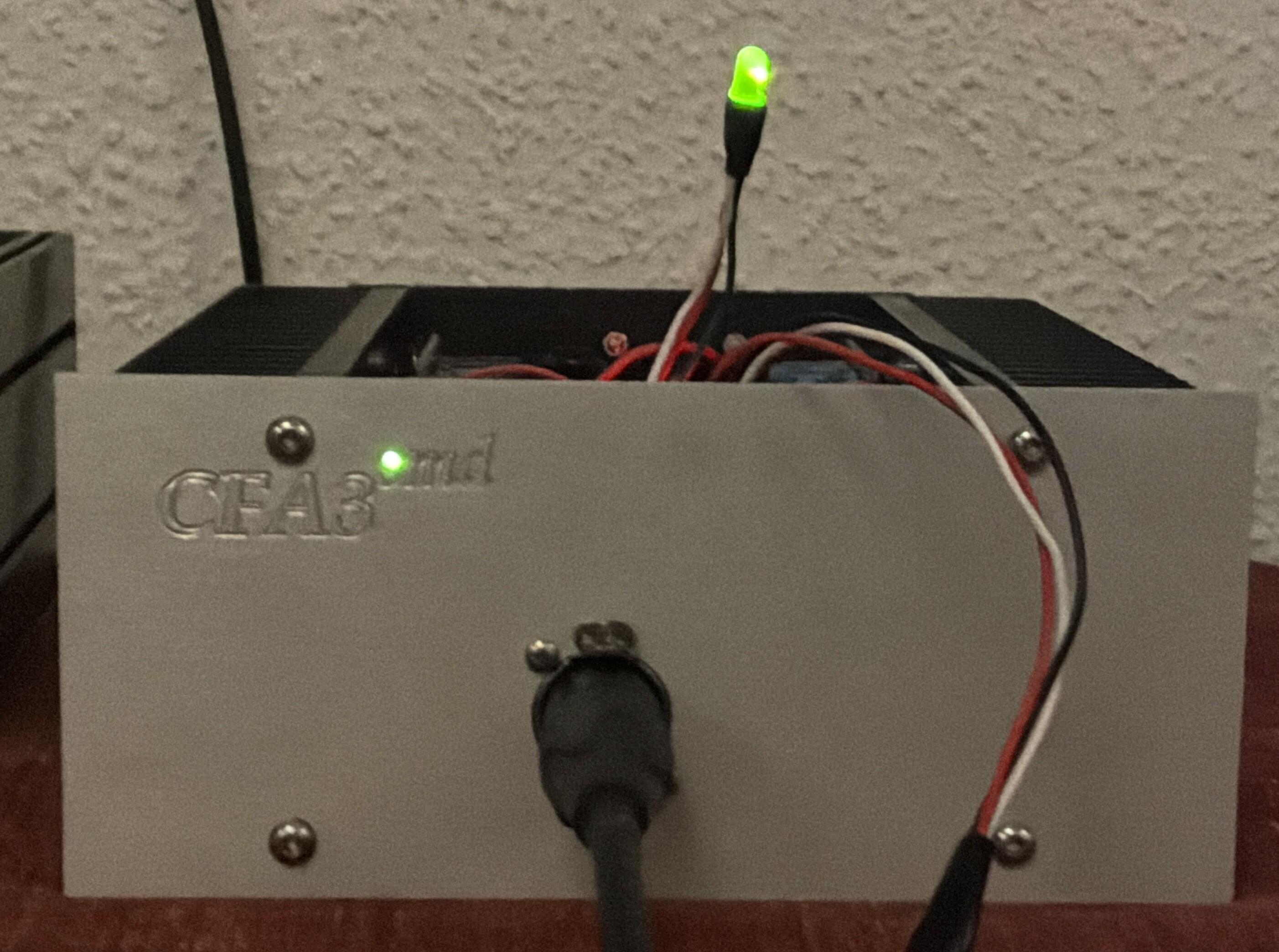
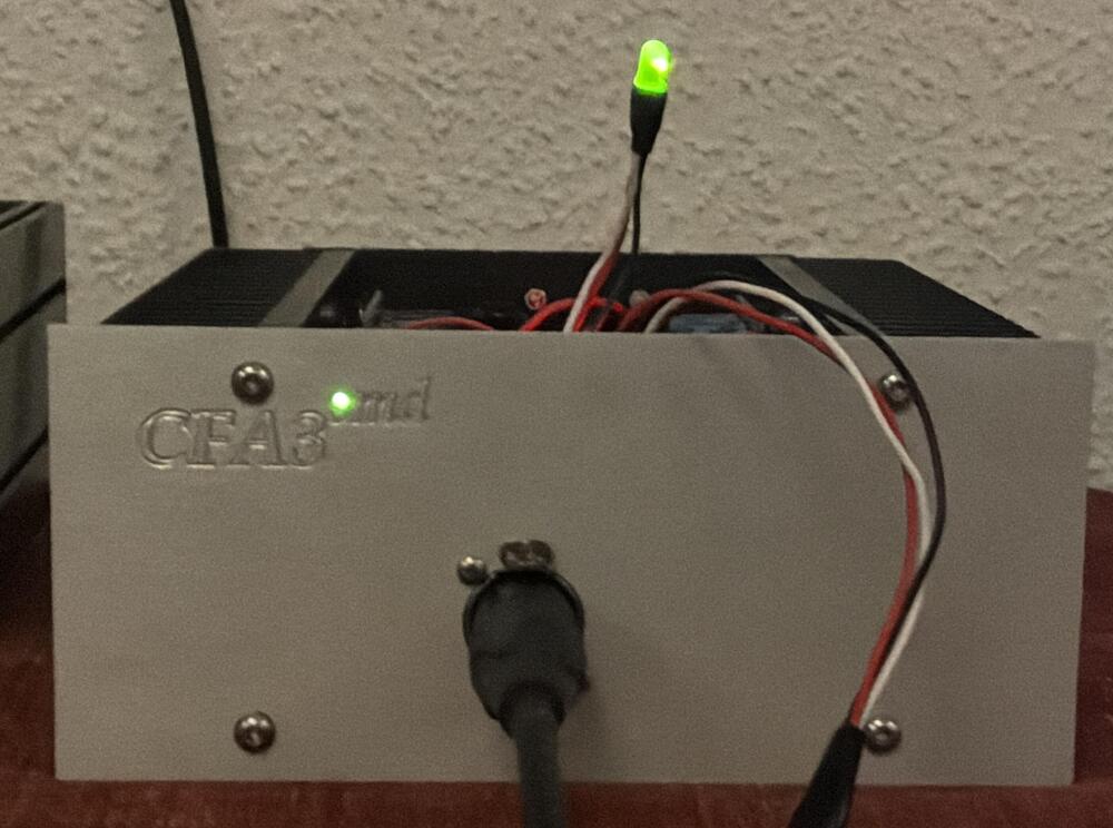
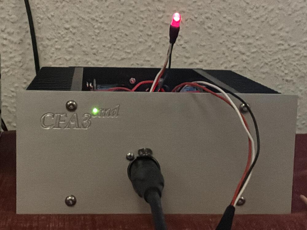
Finished the right channel today. Feedback as suggested by Justin. Bias servo as suggested by Kevin. Red smoke – Super Symmetrical mode. Green smoke – Zero Feedback mode.
-
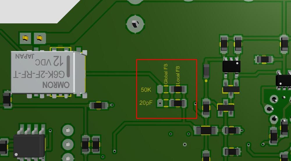
Global or Local feedback? Populate within red square accordingly. Minor change to existing board.
-
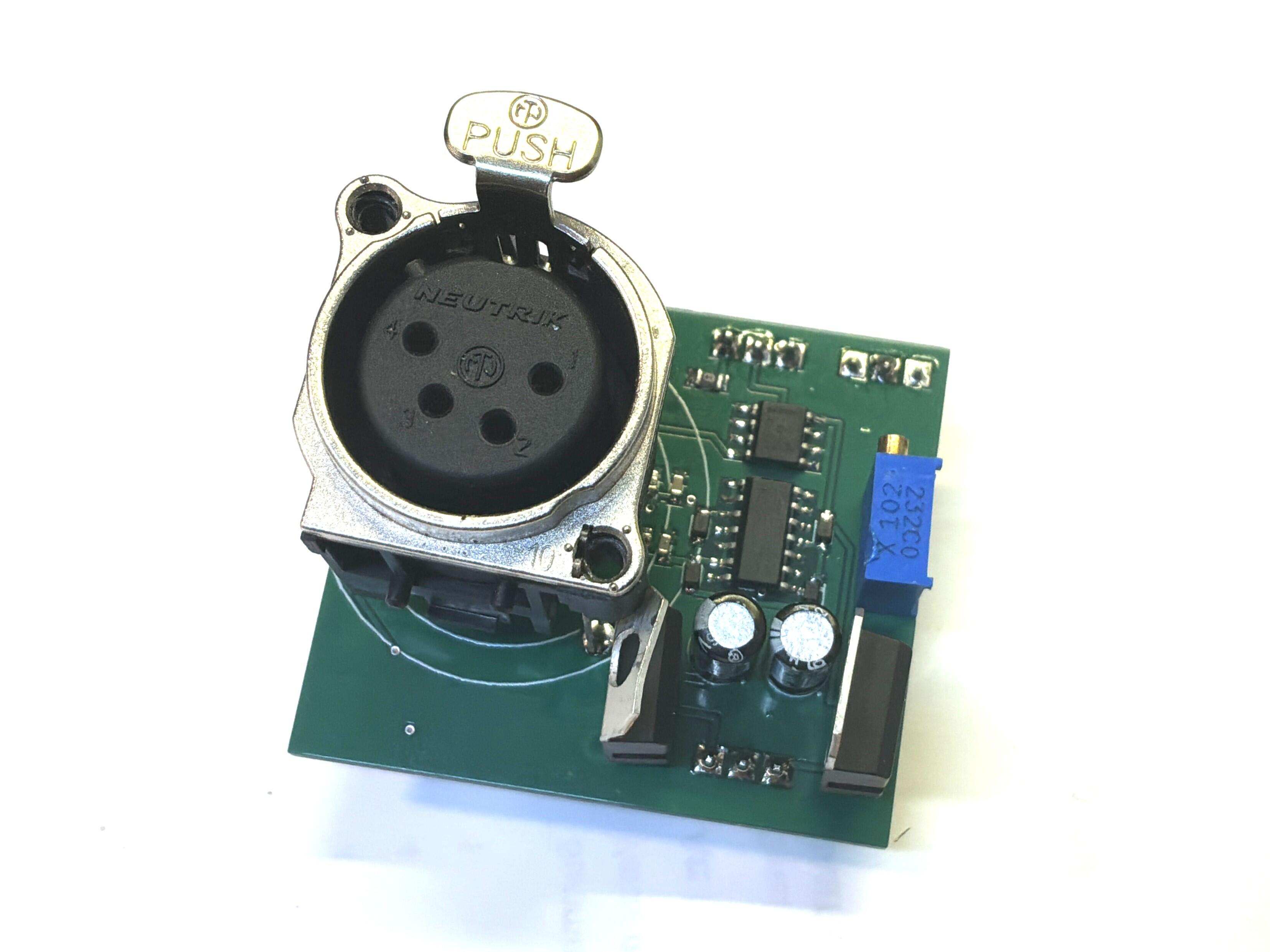
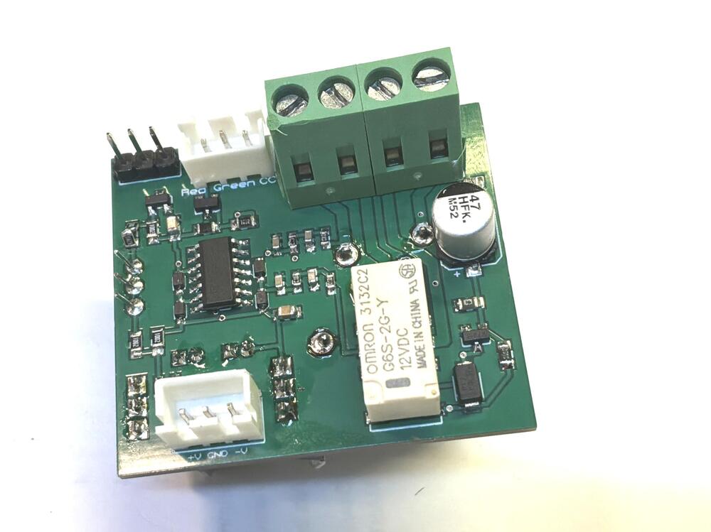
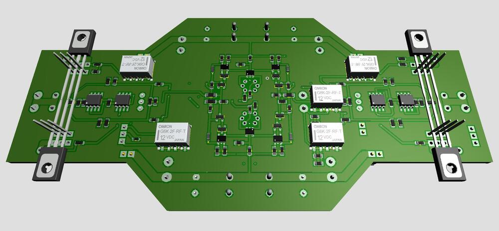
New headphone protector. Four layers board. Two LM4040 2.5V references. Limits set to ~ +/-20 mA.

-
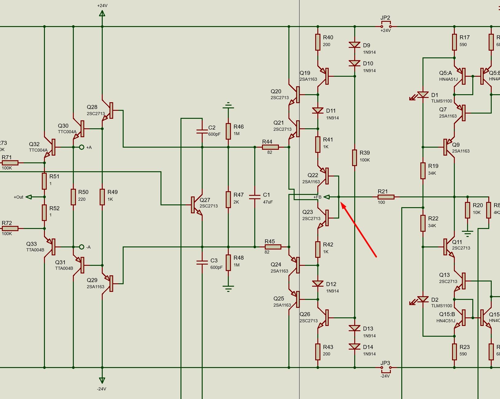
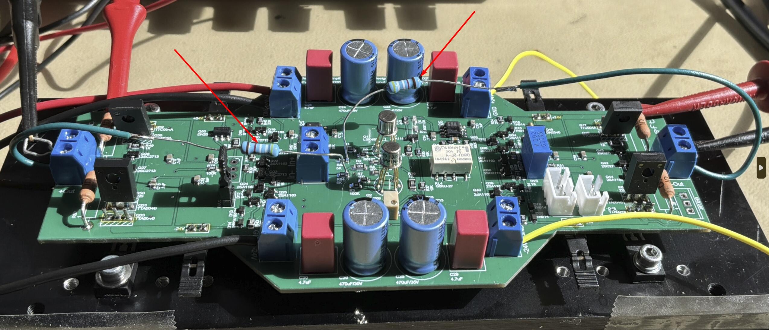
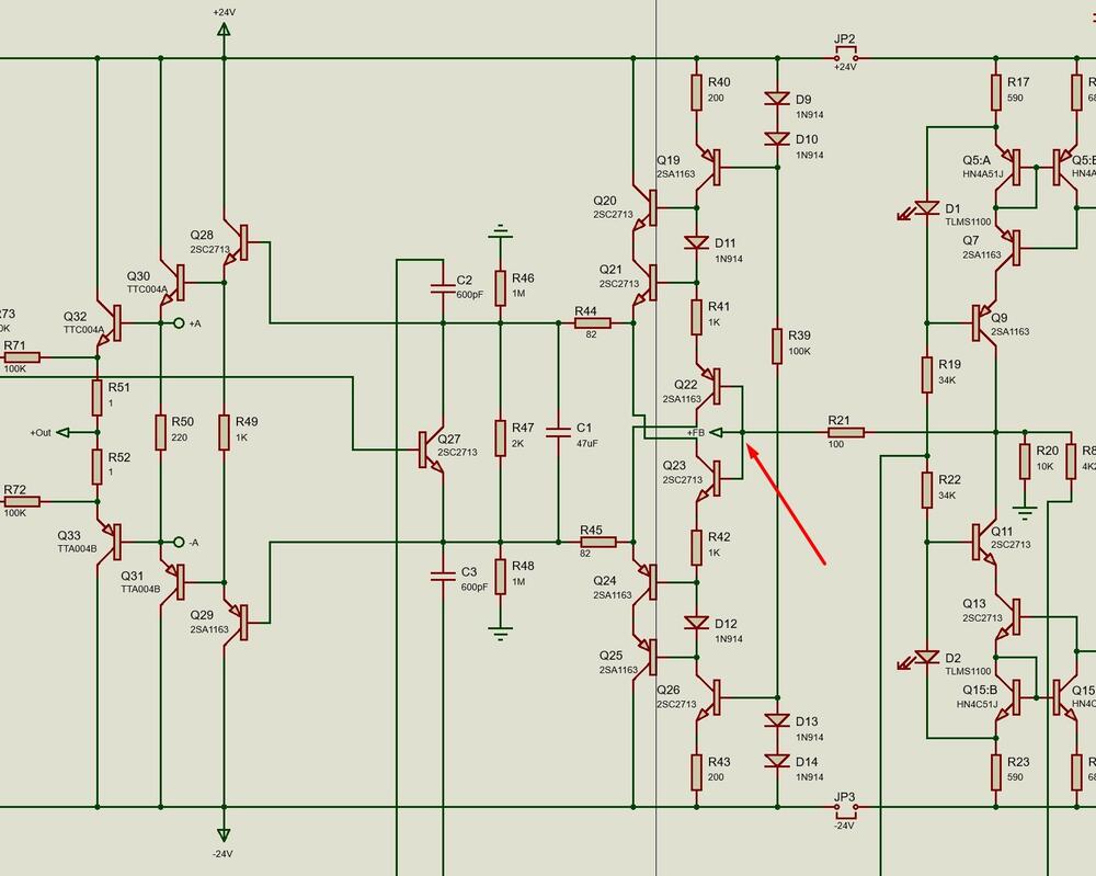
Thanks. I moved feedback from output to after R21 – red arrow. Not sure if that was what you meant. Anyhow, now SS mode works with the 20 pF capacitor. It was an easy mod – just some Kapton film and short wires. Sometimes you are lucky.
-
Some progress. After removing 20 pF capacitor in feedback line switching between ZF and SS bias and offset remain more or less unchanged. It seems that the bias servo doesn’t work well with capacitor in feedback line. My bias servo differs some from what Kevin has suggested in this thread. Only built one SS/ZF board so far. To be continued…

-
Thank you guys! Maybe your information will help me with the problem I've with my CFA3smd in SS mode. Removed feeback resistors from board and wired 50K xicons (at red arrows) from outputs to after 5K resistors at inputs. Now steady bias and zero offset. So far so good. But it's still on the kitchen table.

-
One board, channel, completed. ZF setup was successfully. SS setup didn’t fall out well. It turned out that I’ve connected the feedback wrong with terrible current draw an 8.4V offset at output. After correction, easily done, offset came down to fluctuating 30-40 mV and BIAS acted all right, but not good enough to be used as an amplifier. Now, I feel I’m done with this project and end it with, IMO, a satisfactory Zero Feedback dynamic amplifier. Perhaps I’ll try to get the SS mode working in some future. Main problem is my eyes and enough steady hands to solder SMD and… lack of competence. I just copy others designs. Thank you Kevin. I have some PCB to much for own use. If interested to try this – ping me. Boards are right and left channels, one version is ZF two layers and the other FF/SS version (SS probably nor working) is four layers. Both versions have issues so they will be for free. A nice contribution to Doctors Without Borders will be appreciated.
-
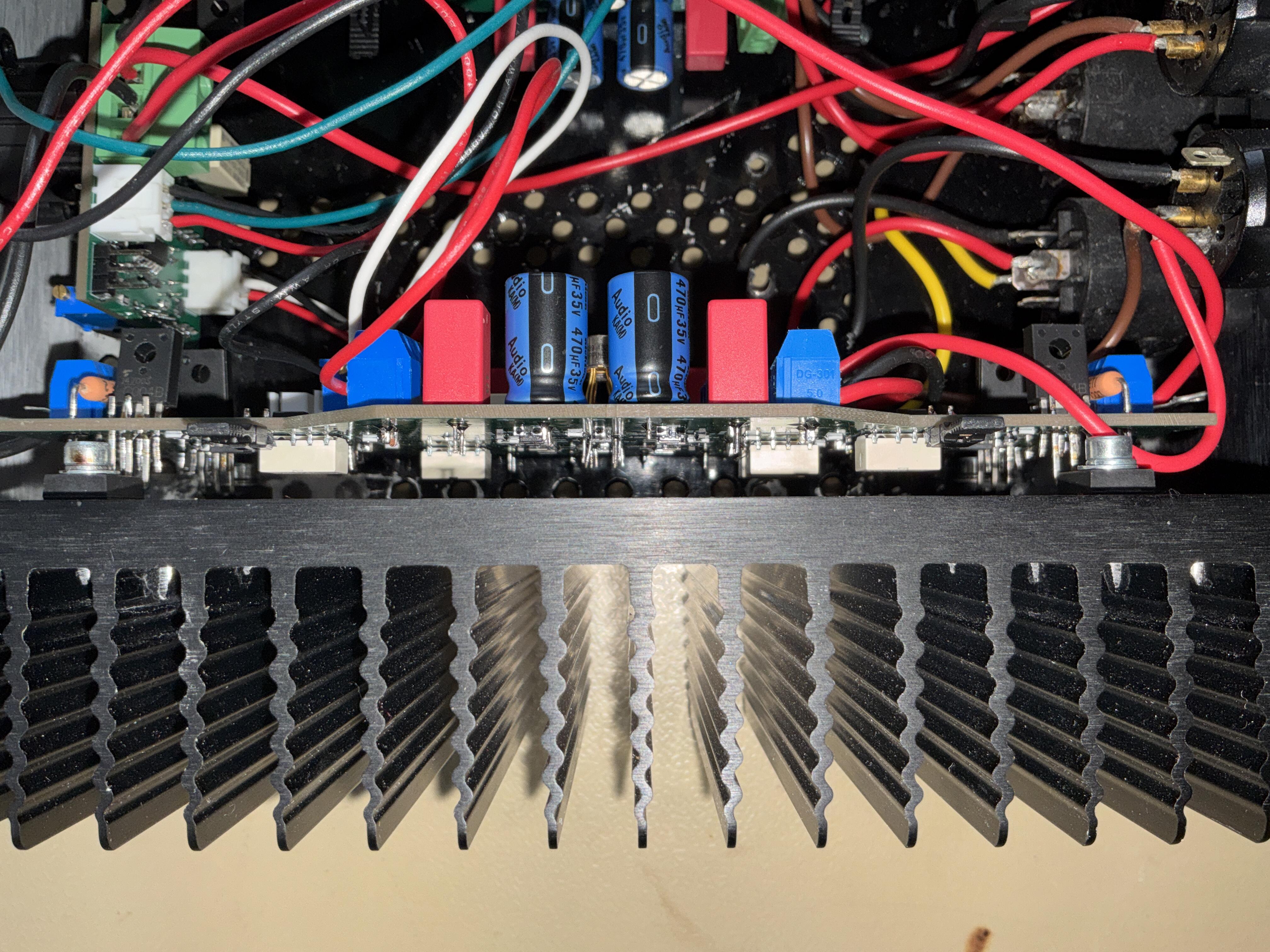
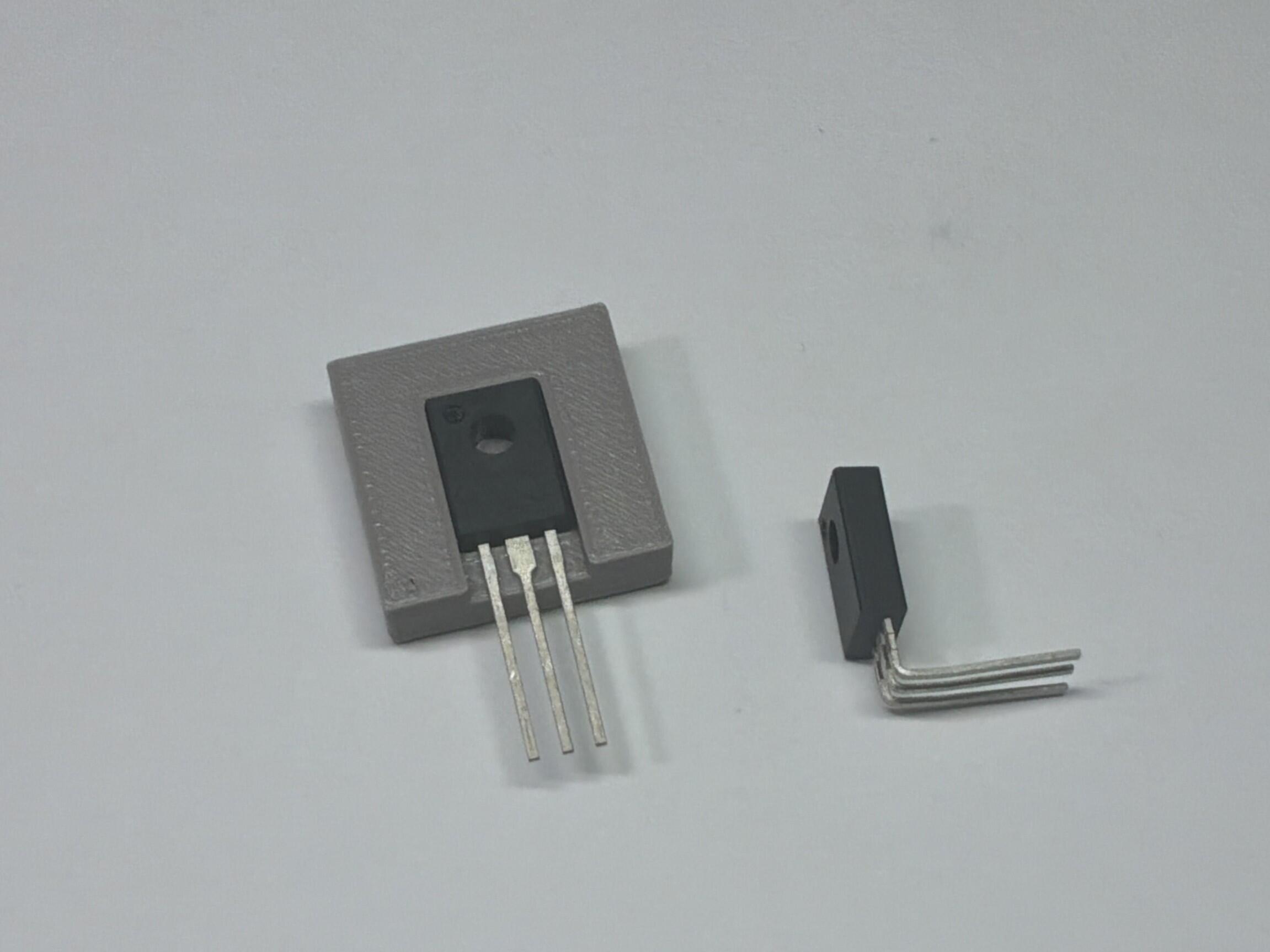
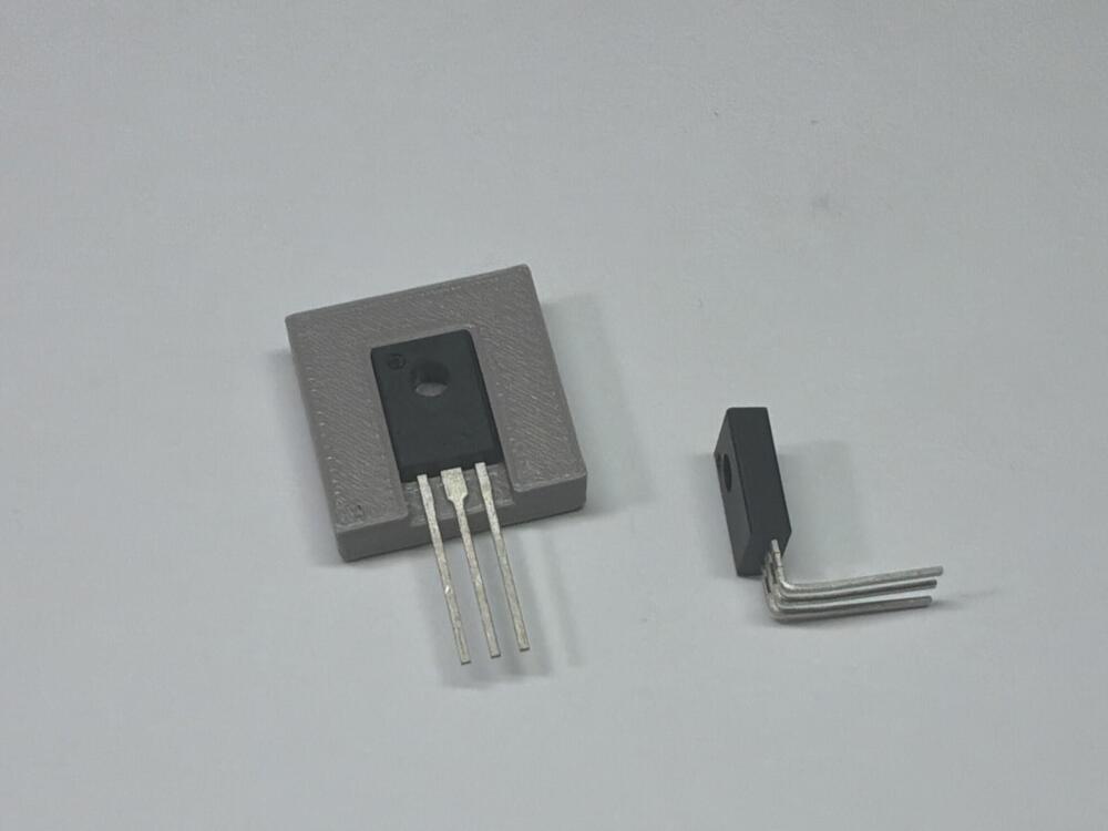
I have chosen Omron G6KU-2F relays, 5.2 mm high. Present space between pcb and heat sink is 9 mm. Can be increase with 1.5 mm. Use of a mica insulator will add another 2 mm. According to datasheet allowed ambient temperature is up to 85 degrees Celsius. Small 3D printed tool to bend output transistor legs. Makes my life easier. Intend to send gerbers to fabhouse in a few days.
-
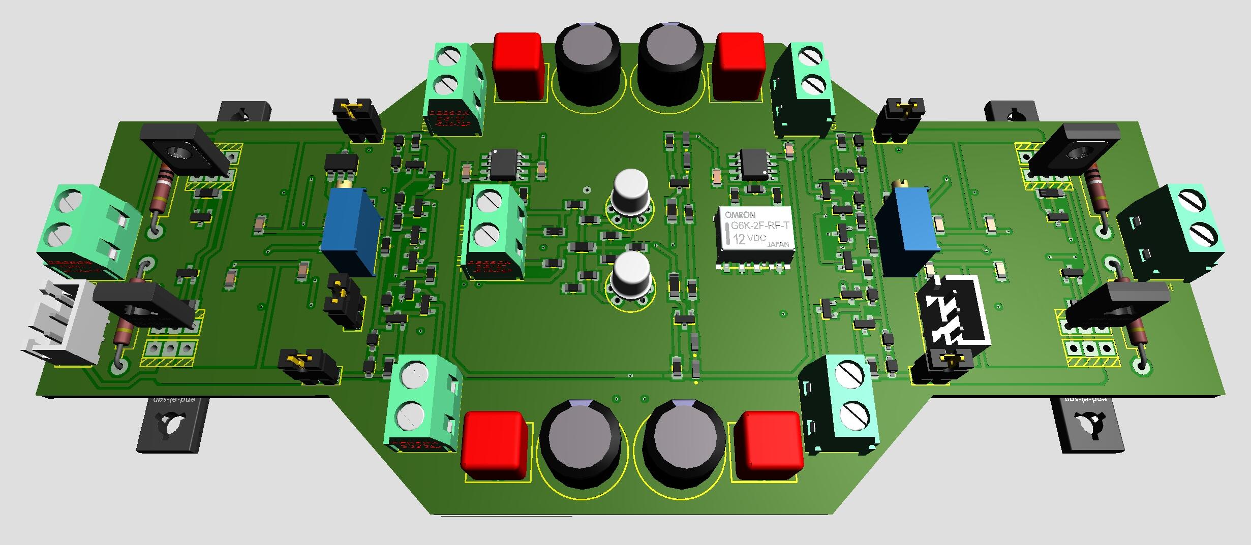
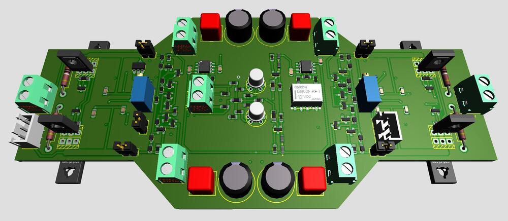
After another week of testing I like the outcome of the latest CFA3smd something with the dual opamp bias servos. Thanks a lot Kevin. My version is a Zero Feedback version of CFA3. I’ve heard, read, that some people favor the Super Symmetrical version. So, here is a drawing drafting of a ZF/SS version of CFA3smd something with… … six small Omron latching relays. Five for ZF/SS switching and the sixth for LED identification of mode in progress. Two JST XH3 connectors for a momentary toggle switch and LEDs to control the ZF/SS modes.
-
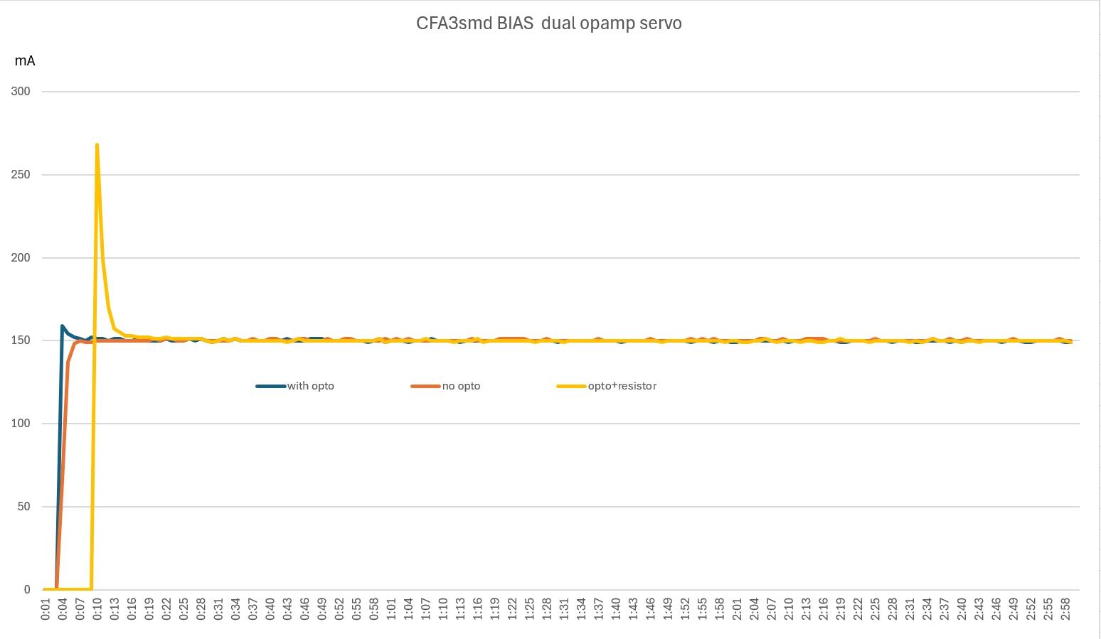
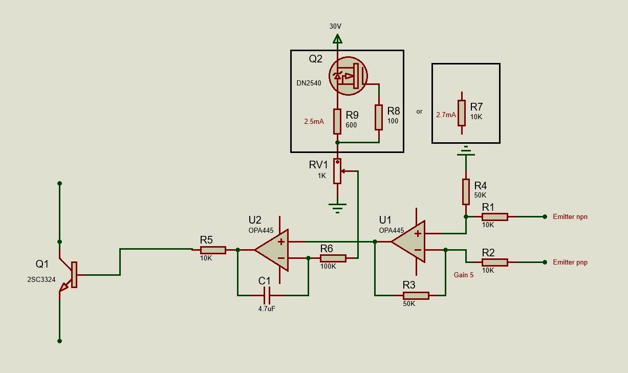
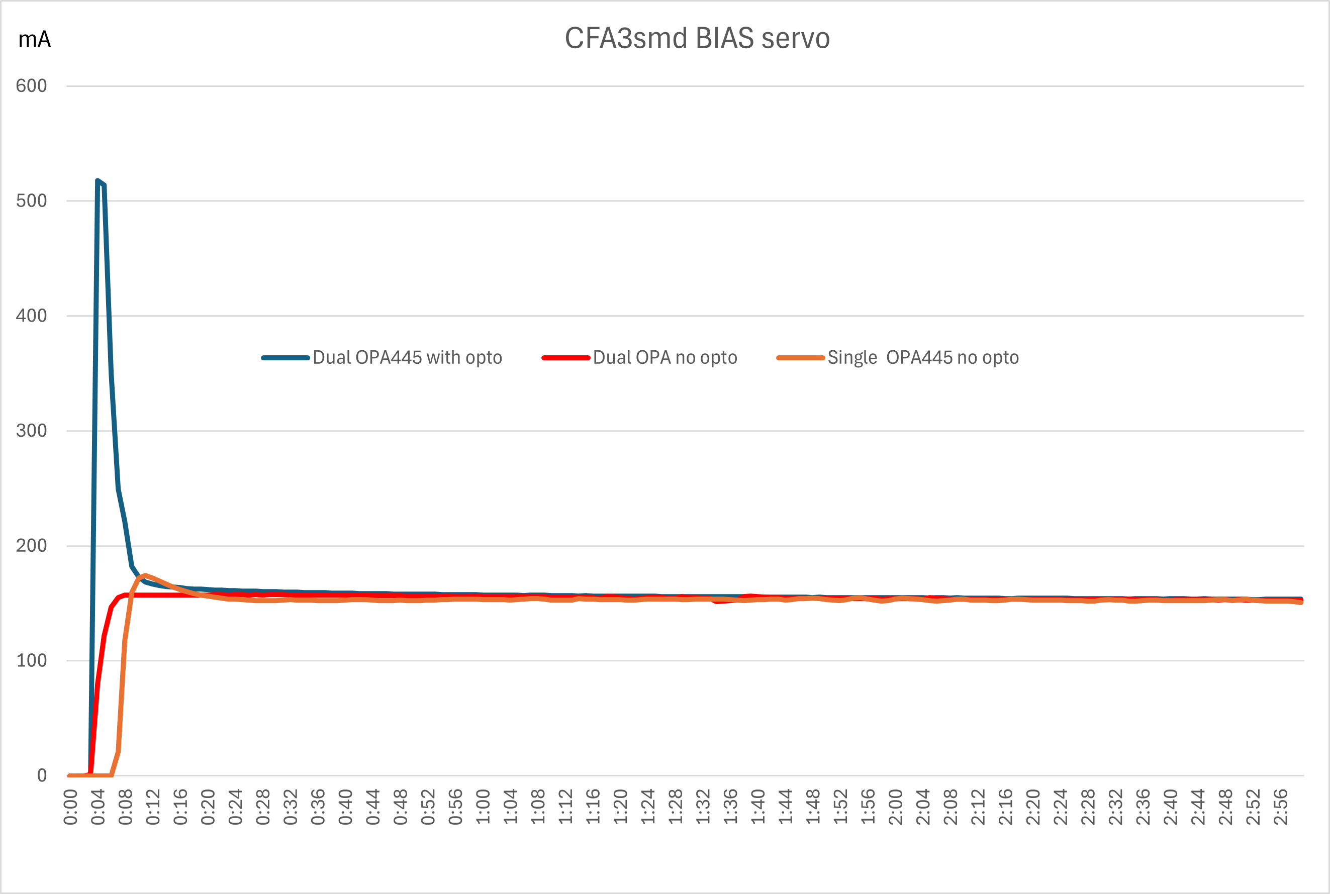
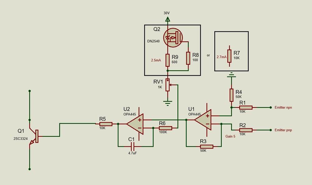
Yes, dual opamp seems to be the way to go. Only changes to the old board are added opa445, opto coupler and three resistors to each bias servo. All operating point unchanged. So, I didn’t follow Kevin’s suggested servo in full. Now the new CFA3smd has been in service a week and I’ve made a few changes to the servos. Increased gain of opamp, increased current through the bias set trimmer and omitted opto coupler. Diagram shows the behavior for servo with and without opto coupler. I also added 7K and 1K resistors (to simulate R36 and RV2, see Kevin’s schematics) and got the yellow (opto+resistor) curve. Schematic showing the final (for now) servo.

-
Happy Birthday!
-
I’ve just finished an updated version of my CFA3smd something. Main difference is dual OPA445 bias servo with optocoupler as Kevin suggested previously in this thread.. Diagram of bias behavior from cold and the first 3 minutes. With optocoupler there is an overshoot before stabilizing at desired 150 mA. Removing optocoupler gives a nice take-of and climb to 150 mA. The diagram also shows the old single OPA445 servo with no optocoupler. It takes some more seconds before start climbing compared to dual OPA445 and a small overshoot before stabilizing.

-
-
Happy Birthday!
-
-
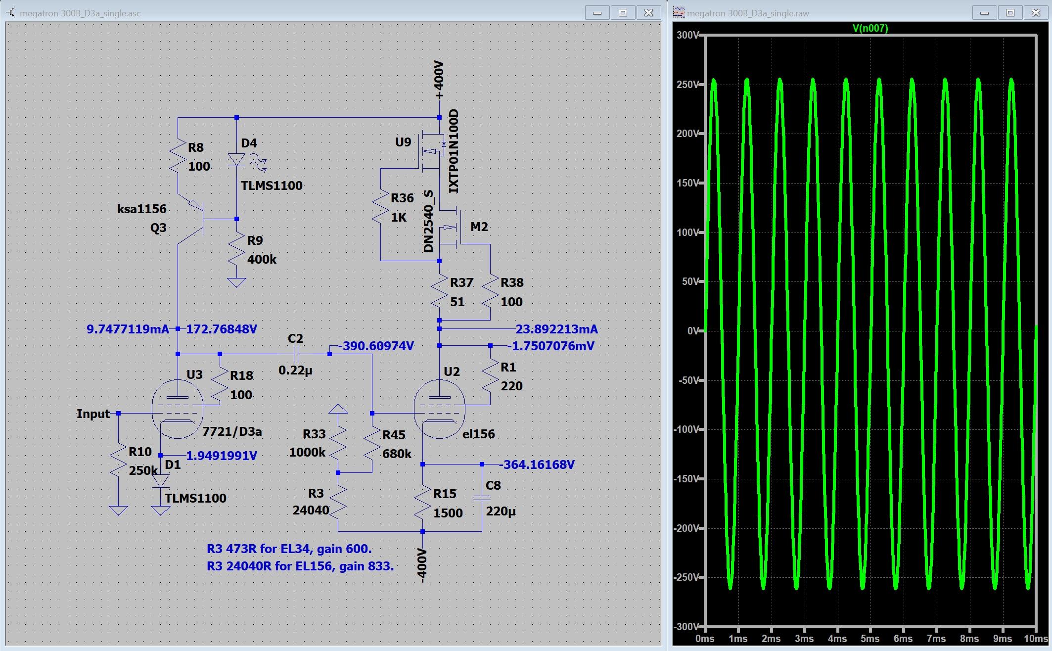
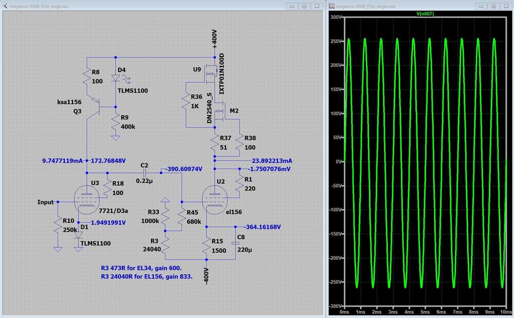
Someone told me D3a is a good tube, Did this in LTspice… Modified Megatron – one less capacitor in signal path and no feedback. Works in LTspice. That's always something.
-
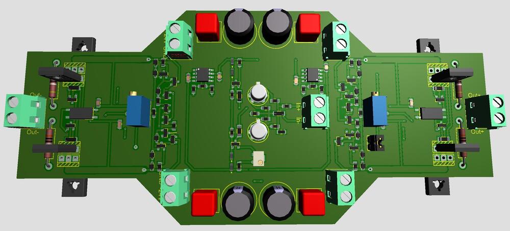
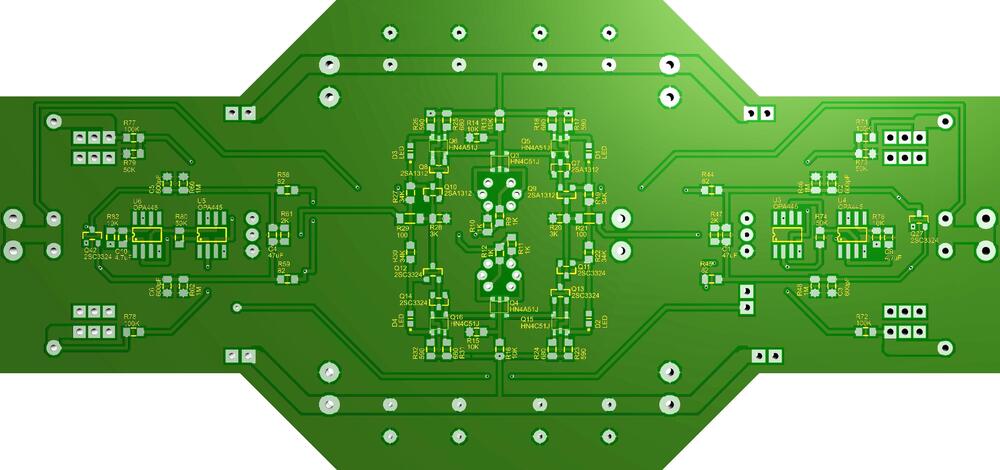
No particular reason behind the jfets, aside I like the to-71 package and that it’s fairly easy to build the layout around them SMD transistors because they are small. I had to decrease current at some locations to reduce heat. I see this amplifier merely as an experiment. I wanted to test if it was possible to make a small board. The bias servo is probably needed while moving from heatsinked MJExxx to small smd transistors. I believe the bias servo previously posted by Kevin, with dual op amps, is preferred. So, another experimental board…
-
Attached ZIP-file with gerbers, shematics and some 3D views. CFA3smd.zip I’ve used both gerbers when I milled the boards (kitchen made) and that is about three years ago. Board size 160mm x 74mm to fit on Modushop 200mm x 80mm heat sinks. Take a look at the files and see if/how the boards could be a part of your project. I think one should make a few changes to attached gerbers before considering sending them to a fab house.
-
I tie cathode direct to -HV, -400 V in my case. Works with EL34, 300B, 2A3, EML 20B-V4 and EL156. The datasheet for my Electro-Harmonix 2A3EH Gold says 450 V maximum plate voltage.
-
-
Higher gain and in my opinion better frequency response. I haven’t tried other than the 100uF electrolytics. With the capacitors the amplifier is an absolute favorite.
-
Happy Birthday!
-
I put 100uF/16V electrolytics in those positions in my Megatron with solid state CCS. I think it made a big difference.
-
Happy belated Birthday!