JoaMat
High Rollers
-
Joined
-
Last visited
Everything posted by JoaMat
-
Thank you everyone. Had a nice one with my wife in our summer(winter)cottage. Now I’m preparing for Boxing Day +6. Birthday of both our children and one grandchild. Happy New Year everyone!
-
Happy Birthday!
-
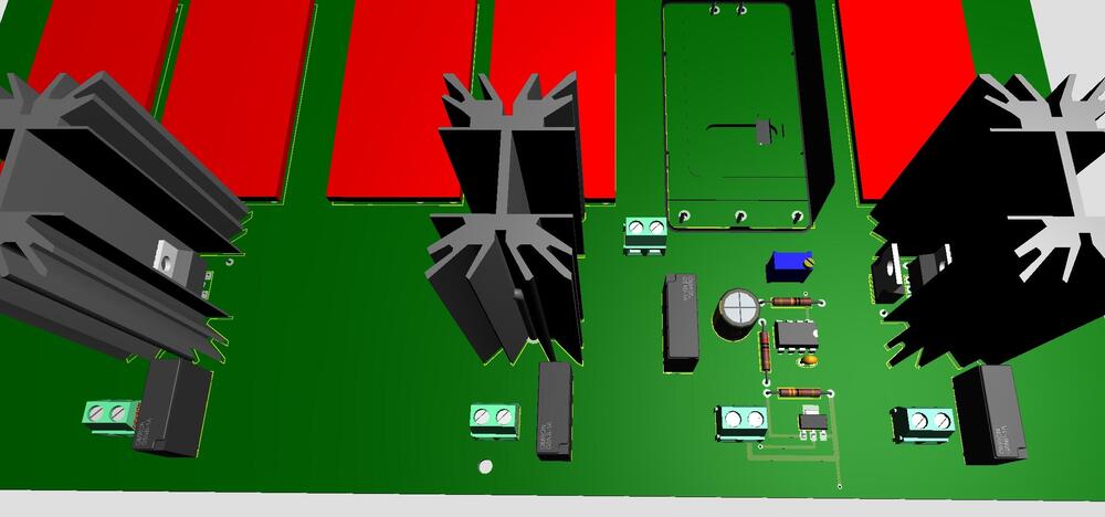
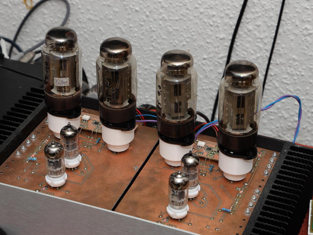
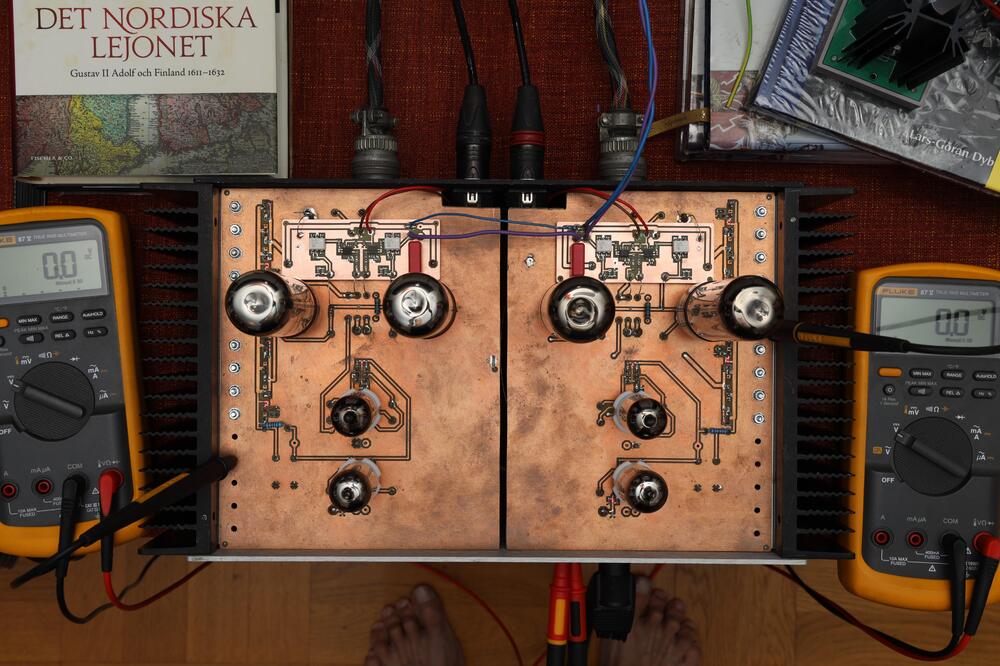
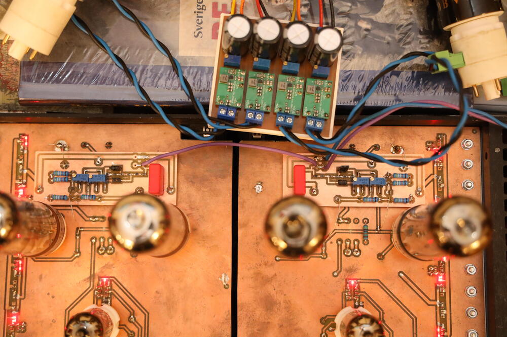
A frendly Head-Caser has kindly lent me four EL156, So, I made myself some EL156 to EL34 adaptors. Here a Megatron SS CCD something with the four EL156. Same friendly fellow has built himself a couple of filament supply for DHT similar to the one in above post.
-
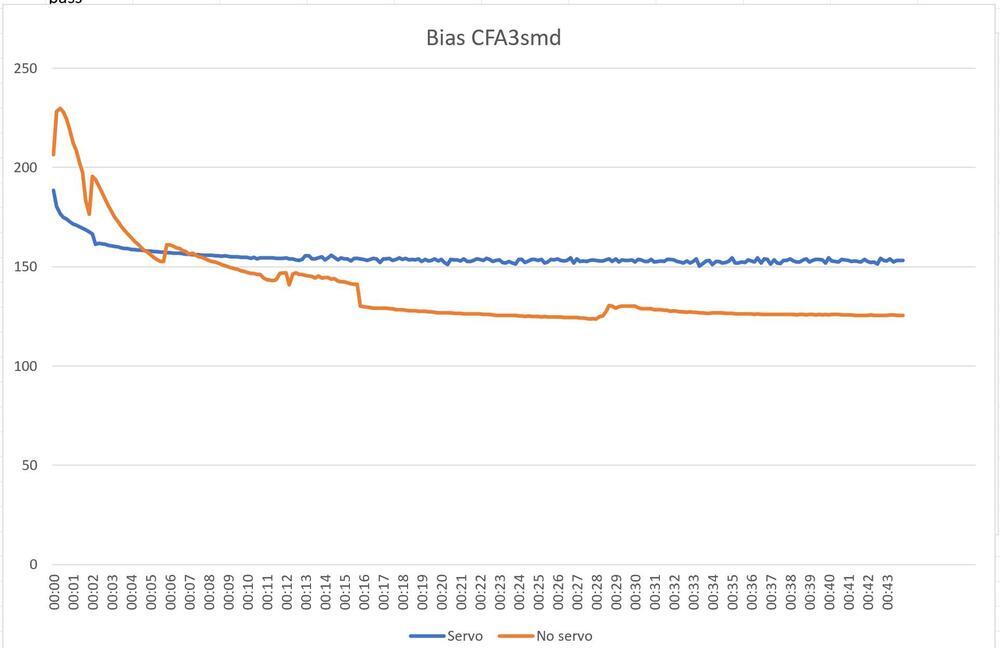
Perhaps you are right, but that’s nothing I can verify. It’s correct that pos input is dancing. Now I think that the neg input is a perfect dancing partner which results in a working servo. With the servo the amplifier behaves similar to the ones without servo except that the bias doesn’t drift. And cross talk? Not a problem - I’m married and used to cross talk.
-
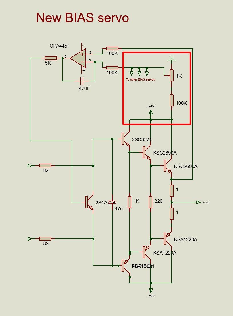
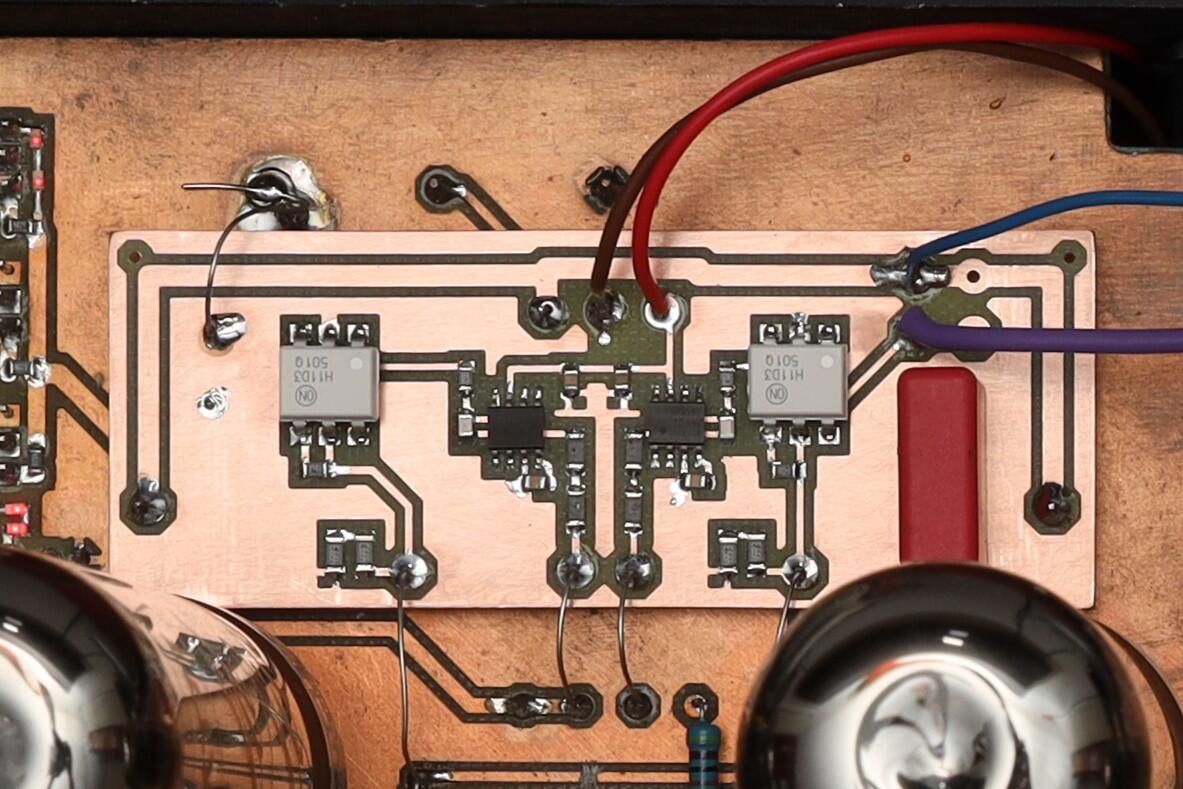
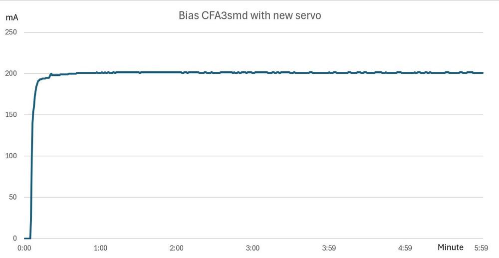
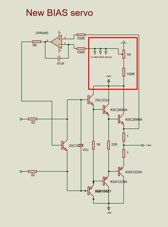
I’ve a smd version of CFA3. Only output transistors on heat sink. Bias is servo controlled. Works all right. Output stage with servo looks like this…
-
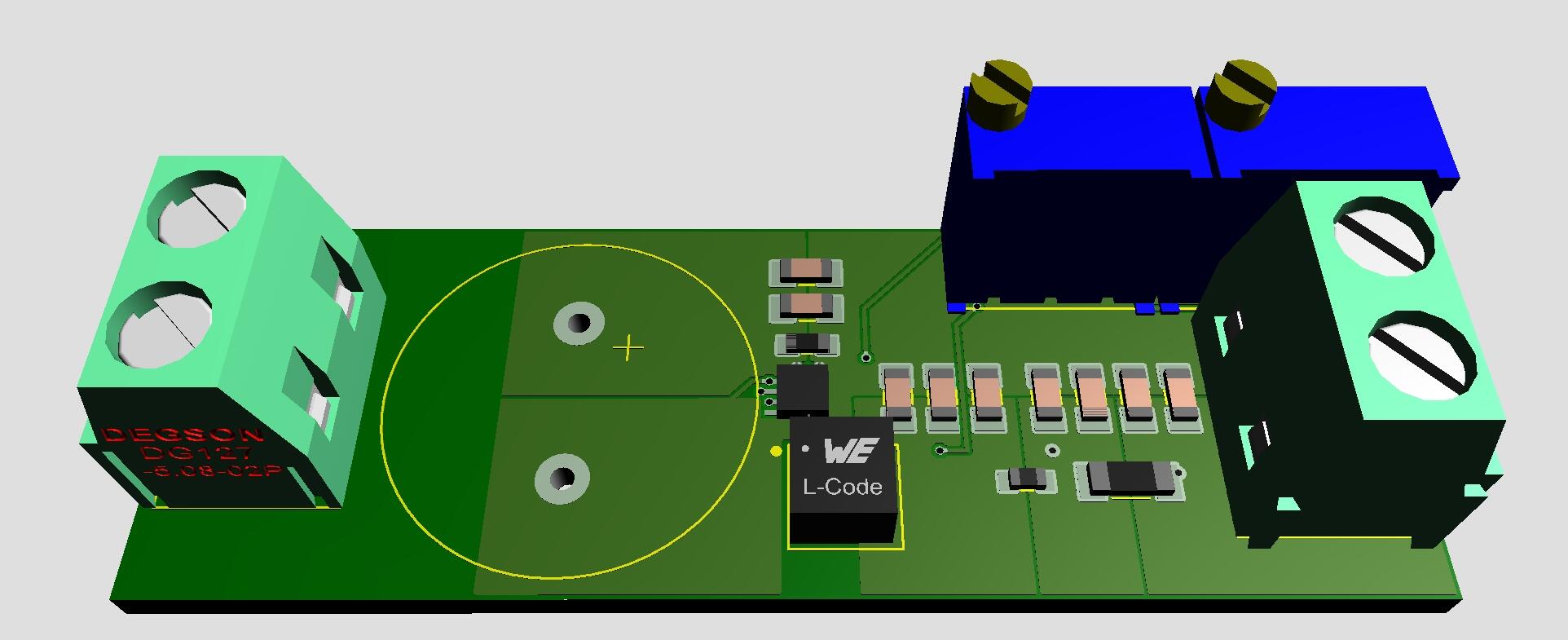
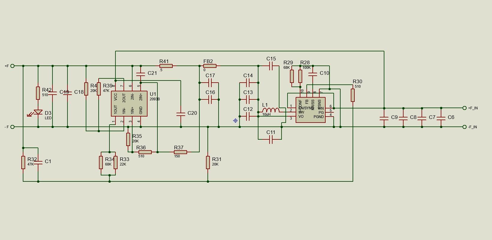
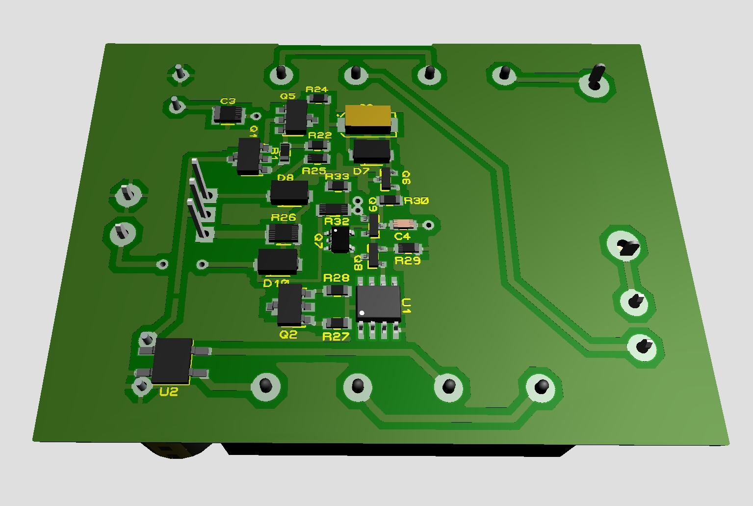
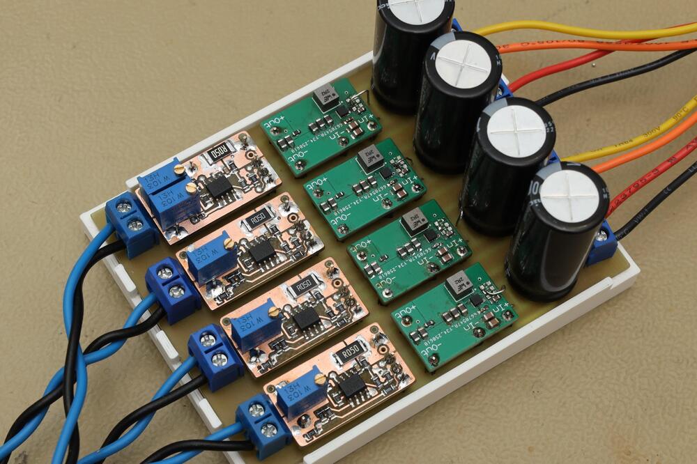
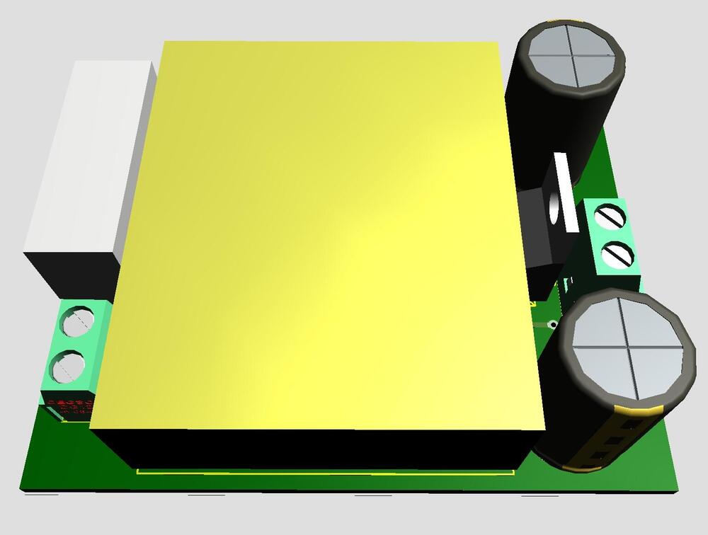
Only in fantasy world... Filament supply for DHT. 9VAC in and 2.5/5.0VDC out. Size 2.07in x 0.7in. All you need is to connect a transformer and a tube to heat.

-
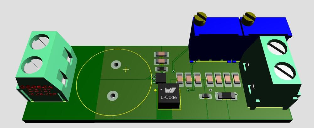
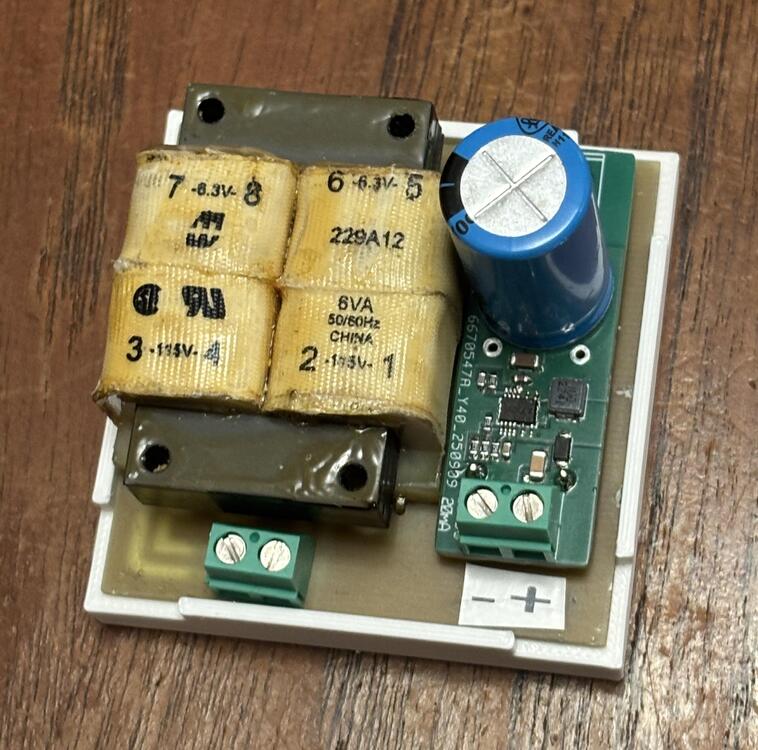
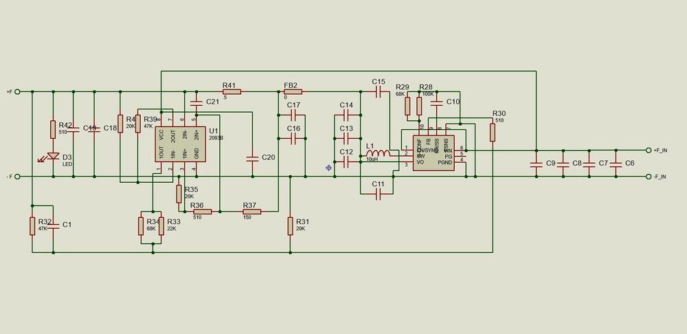
A small 120 V supply for above grid voltage control. 6.3VAC Hammond 229A transformer and LT8365 DC/DC converter. Out 120V . Size 2.3in x 2.3in.
-
Seems simmconn reads shematics. Regarding Q12, schematics and gerbers don't match, I think.
-
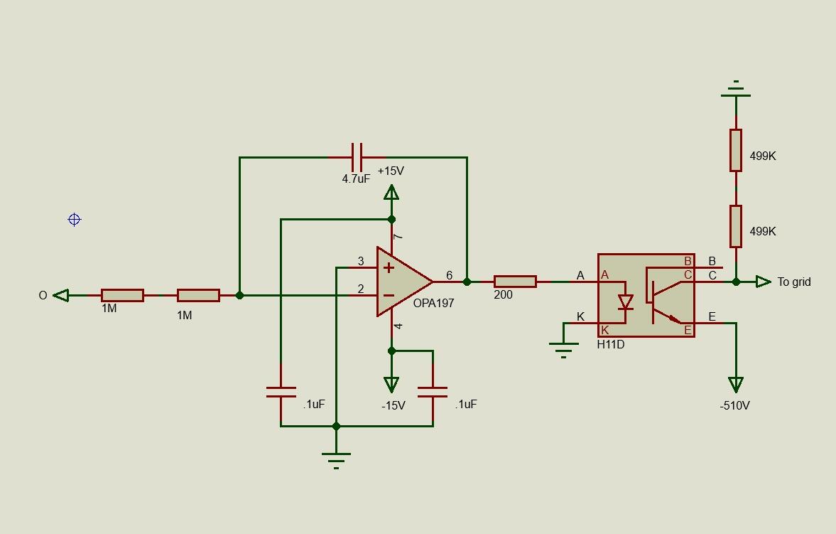
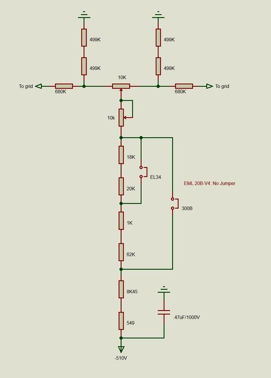
Completed servo controlled grid voltage. Works with EL34, 2A3, 300B and EML 20B-V4.

-
Did this today. A two-trimmer control board. Here along with three one-trimmers. One trimmer affects both 2A3 and 300B filament voltages and the second just the 300B voltage.
-
The one-trimmer control board above adjusted voltage for both 2A3 and 300B at the same time. No way to adjust voltage for one without effecting the other. I assumed that it should be possible to set voltages for one tube and have the other unaffected. But as my brain isn’t as fast as the two comparators in LM2903 I made a test board with seven trimmers. After some trimming back and forth I found one trimmer that adjusted voltage for both tubes and an another that just affected 300B, So, next is a two-trimmer control board, same size as the one-trimmer. If you don’t understand how a circuit works, the trial-and-error method might help you.

-
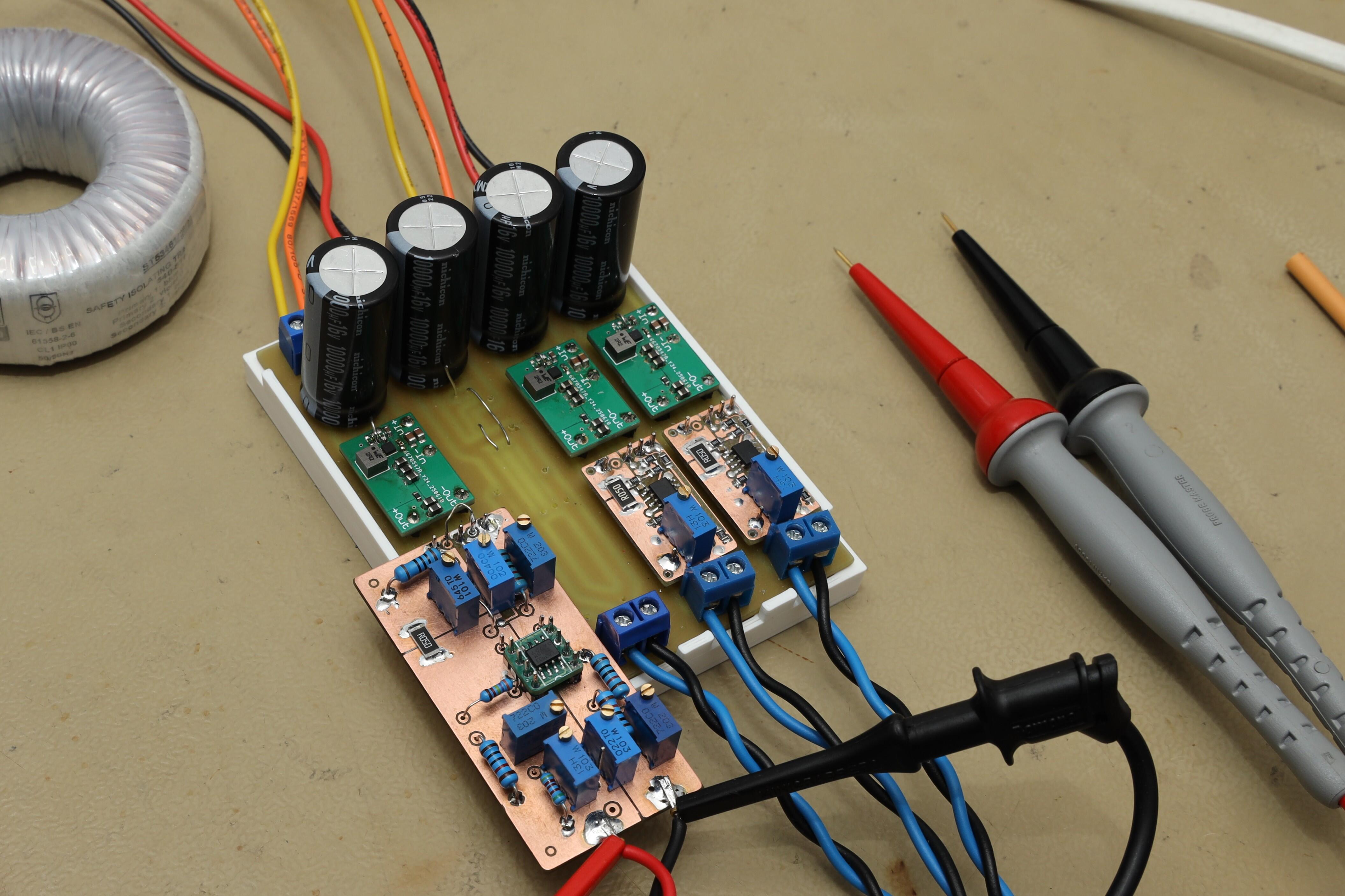
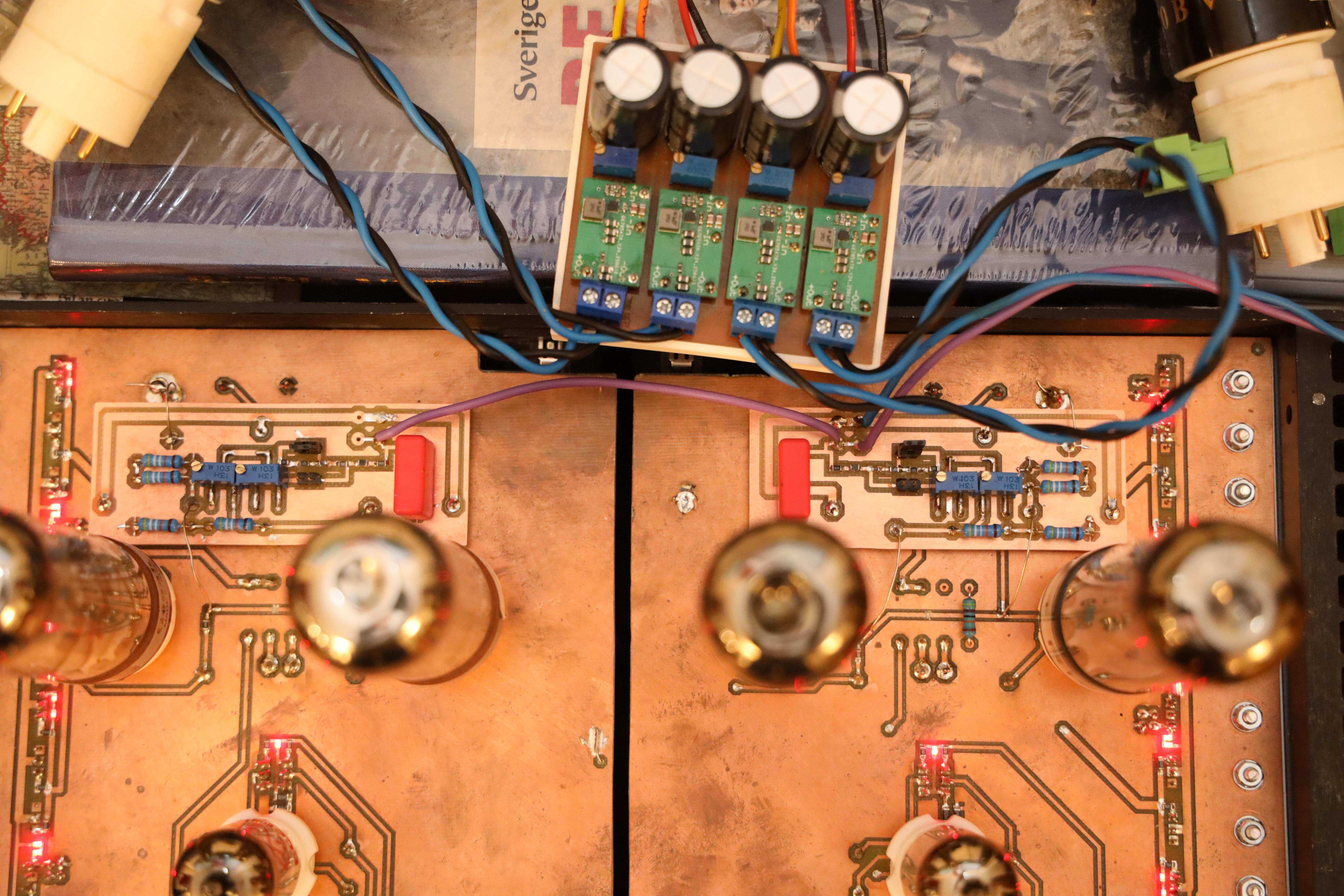
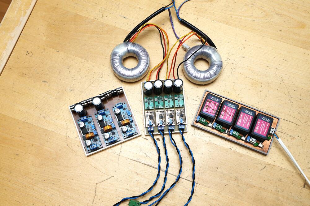
Three kinds of switching mode filament supplies made in my kitchen. Right: Traco brick, only 5V with some fine adjustment, designed by Kevin Gilmore and slightly modified by me. Left: DC-DC Step Down Converter XL4015, adjustable voltage and current limiter, have used it for 2.5V to 6.3V. Middle: TPS62913 Low Ripple Buck Converter (green board) My own design but done with help of TI datasheet (all info needed is there). Copper color board is an Elekit regulator with 2A3 and 300B auto detection. I’ve added a trimmer for fine adjustment of voltage. All three seem to work all right with my electrostatic amplifiers. I also have Pete Millett, Tentlabs and Coleman filament regulators. They are all bulky with heat sinks and produces a lot of heat. Yes, I do agree. Yes, at some point it (probably) will be a different matter.
-
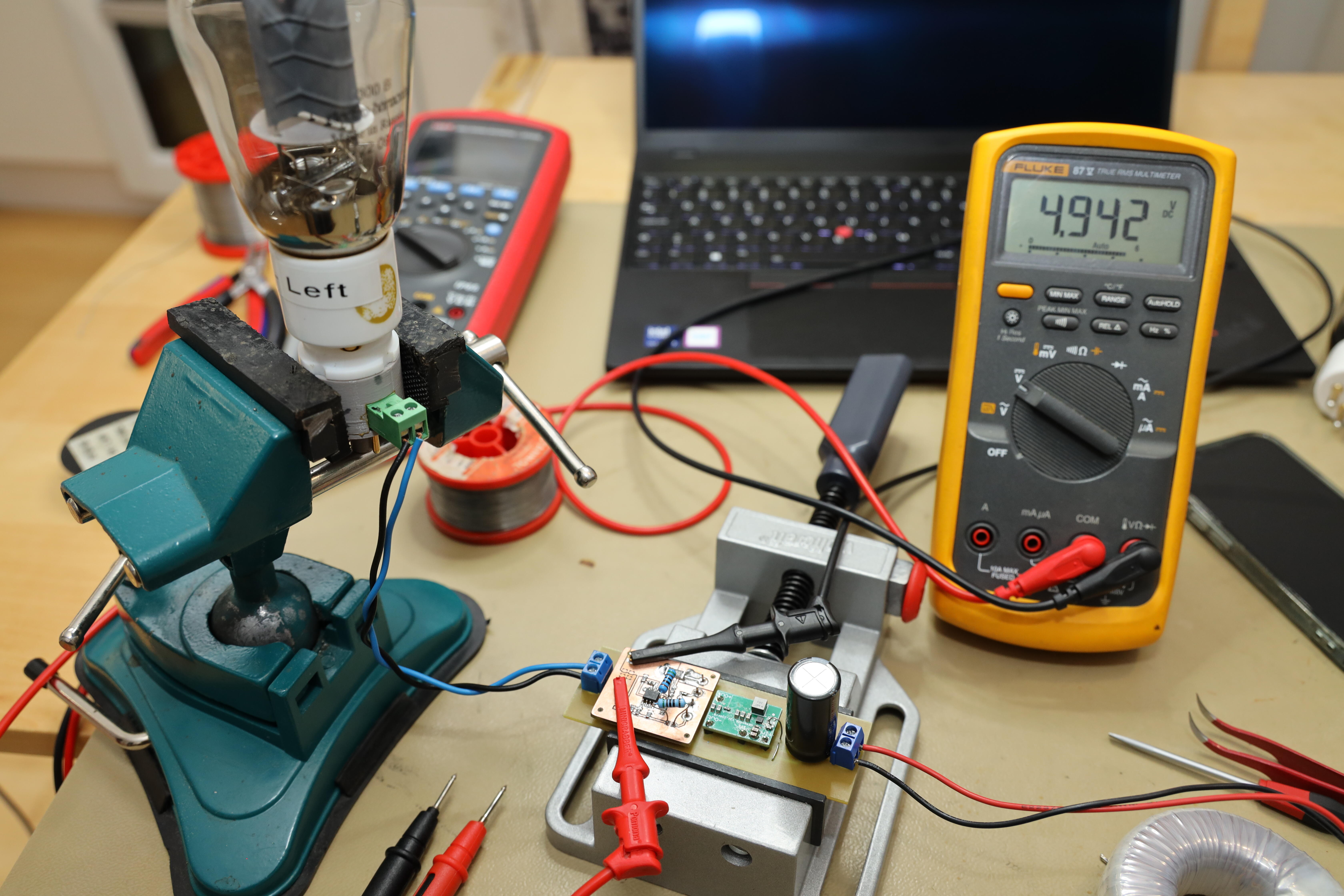
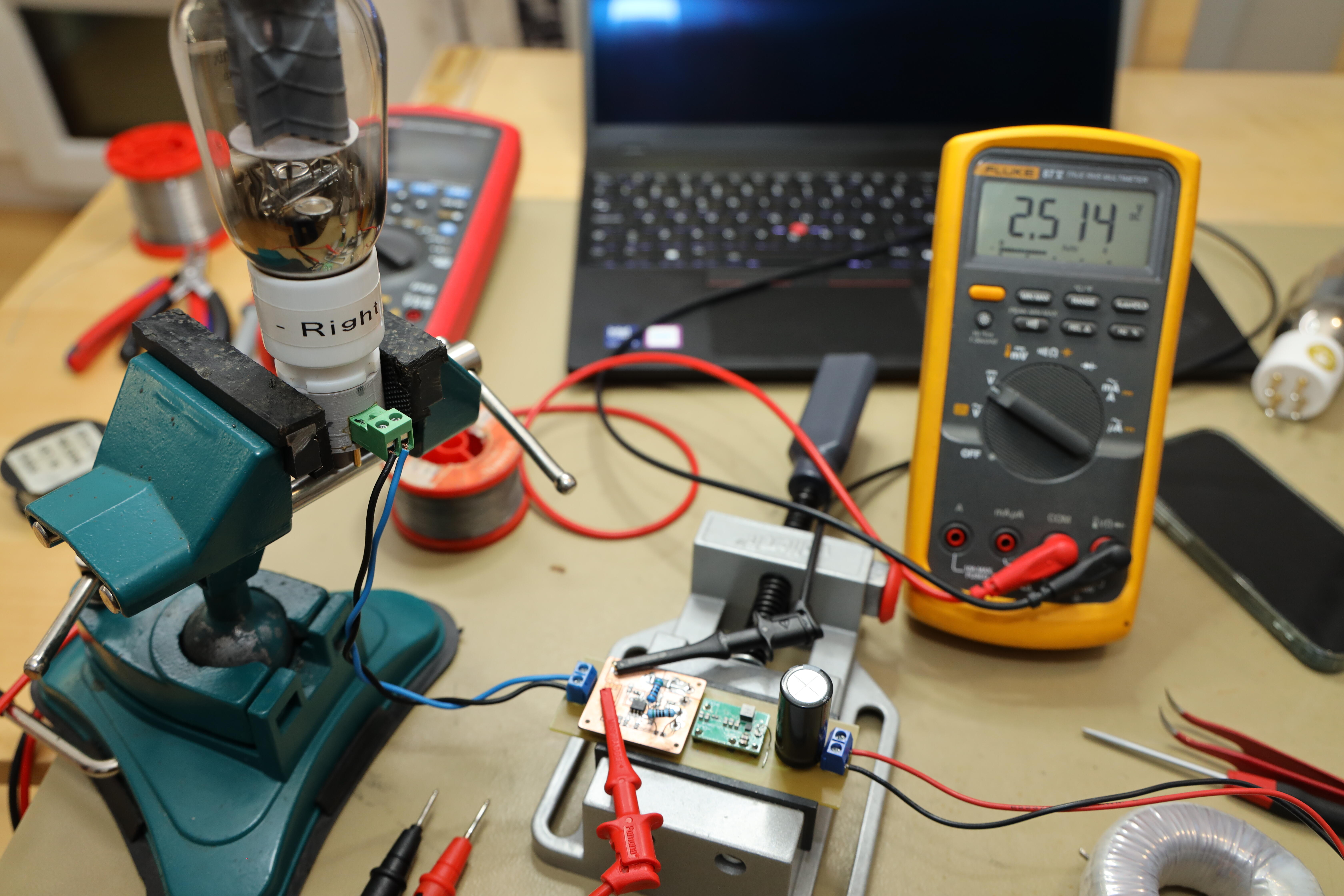
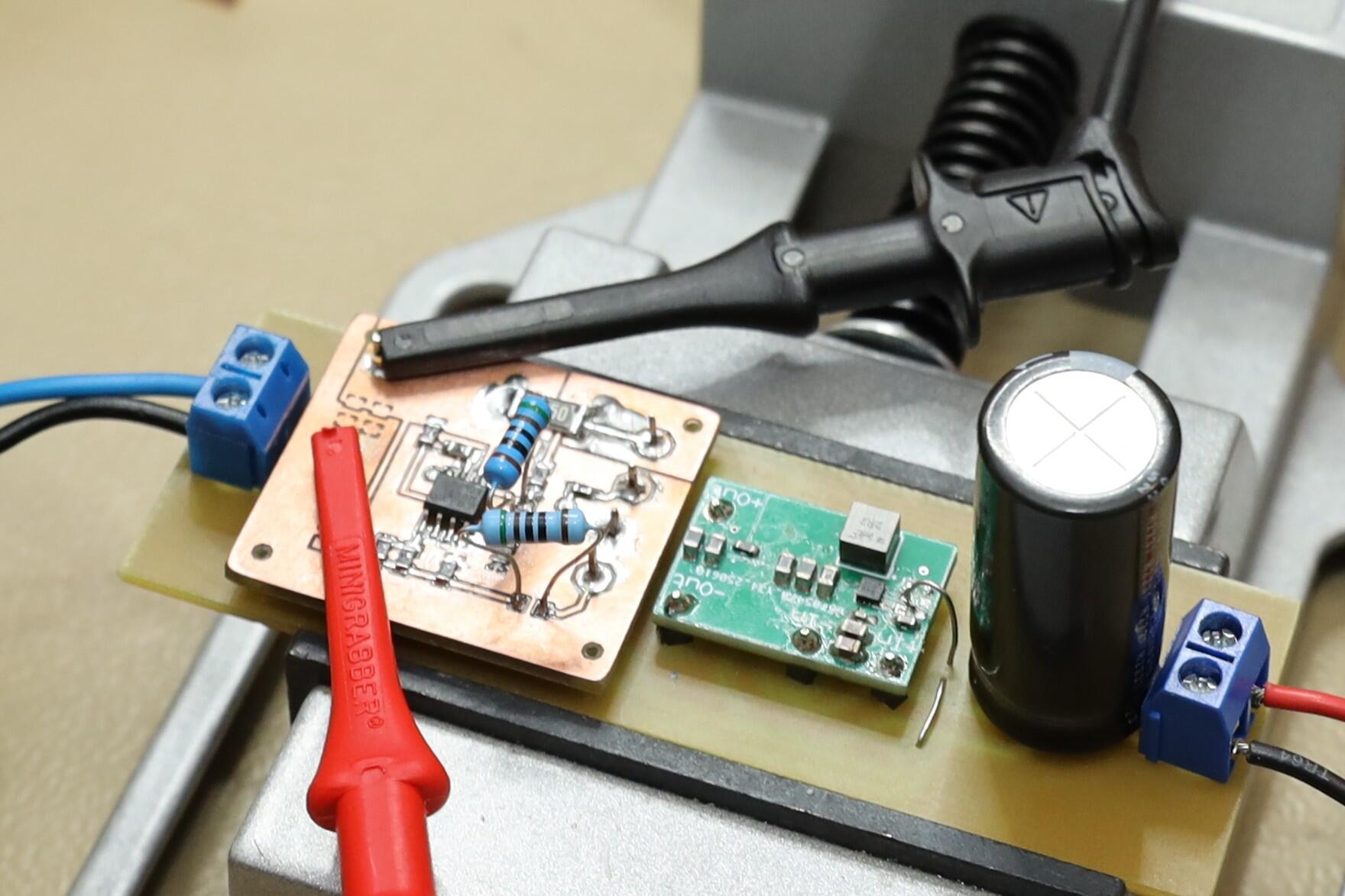
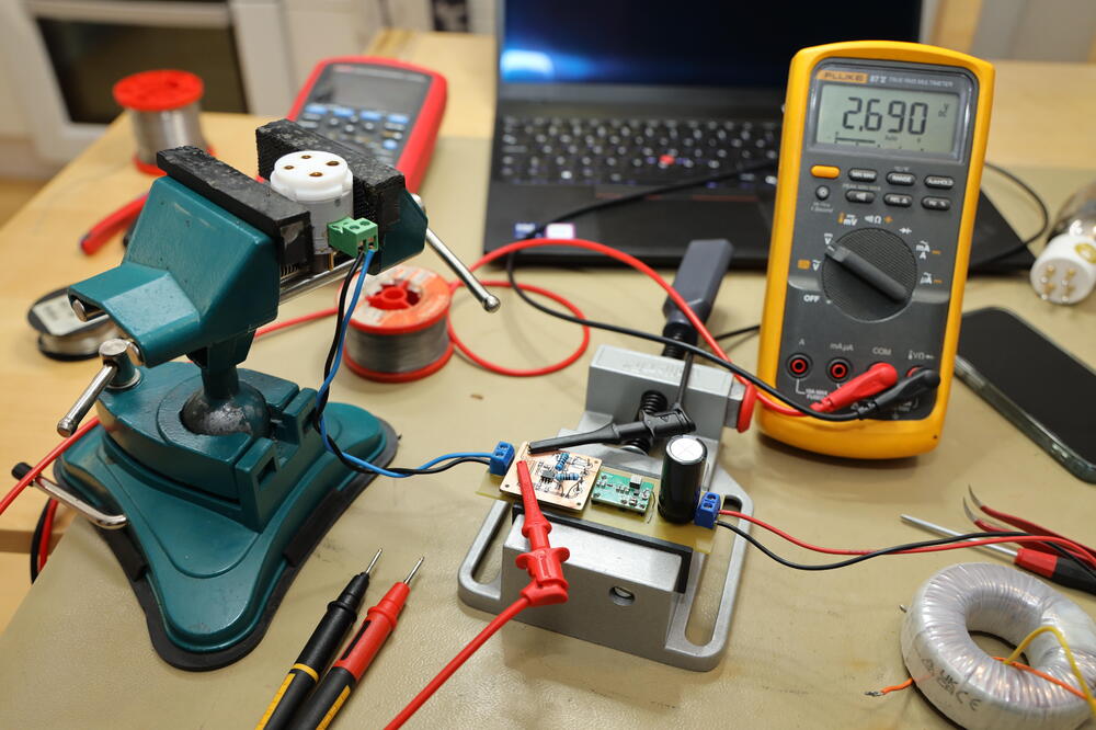
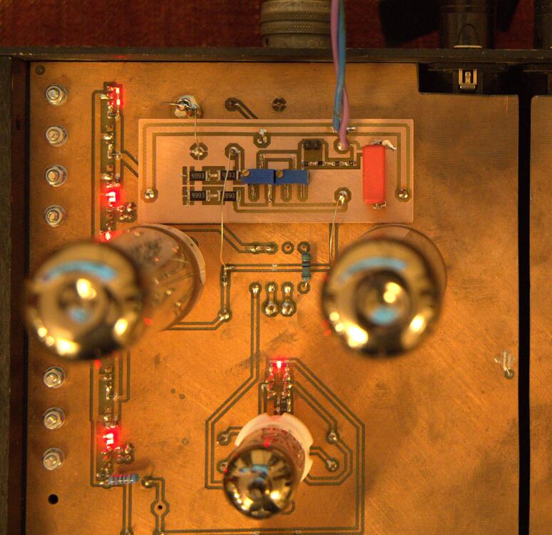
Made a control board for filament smps today. Some pictures from my kitchen. Idle voltage – no tube 2A3 300B and EML 20B-V4


-
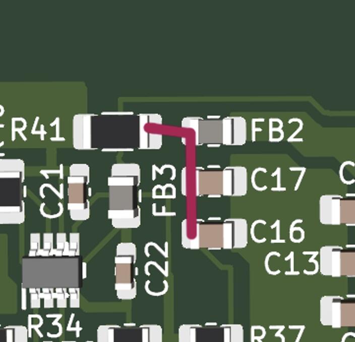
I believe R41, FB2, C16 and C17 are connected as red line shows.
-
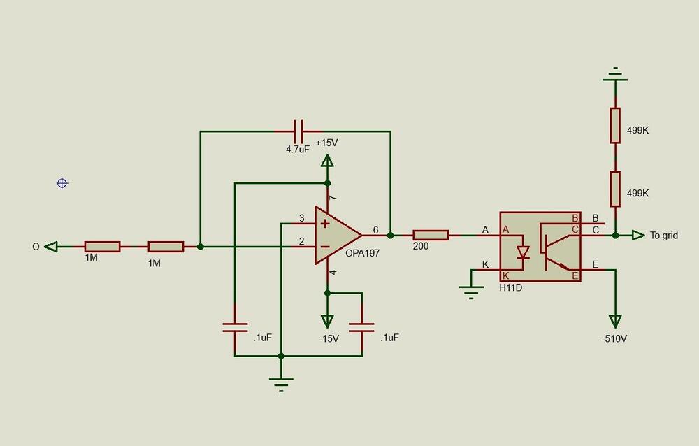
Thanks a lot. I've been thinking of a 300K resistor cross the h11d to limit the upper grid voltage.
-
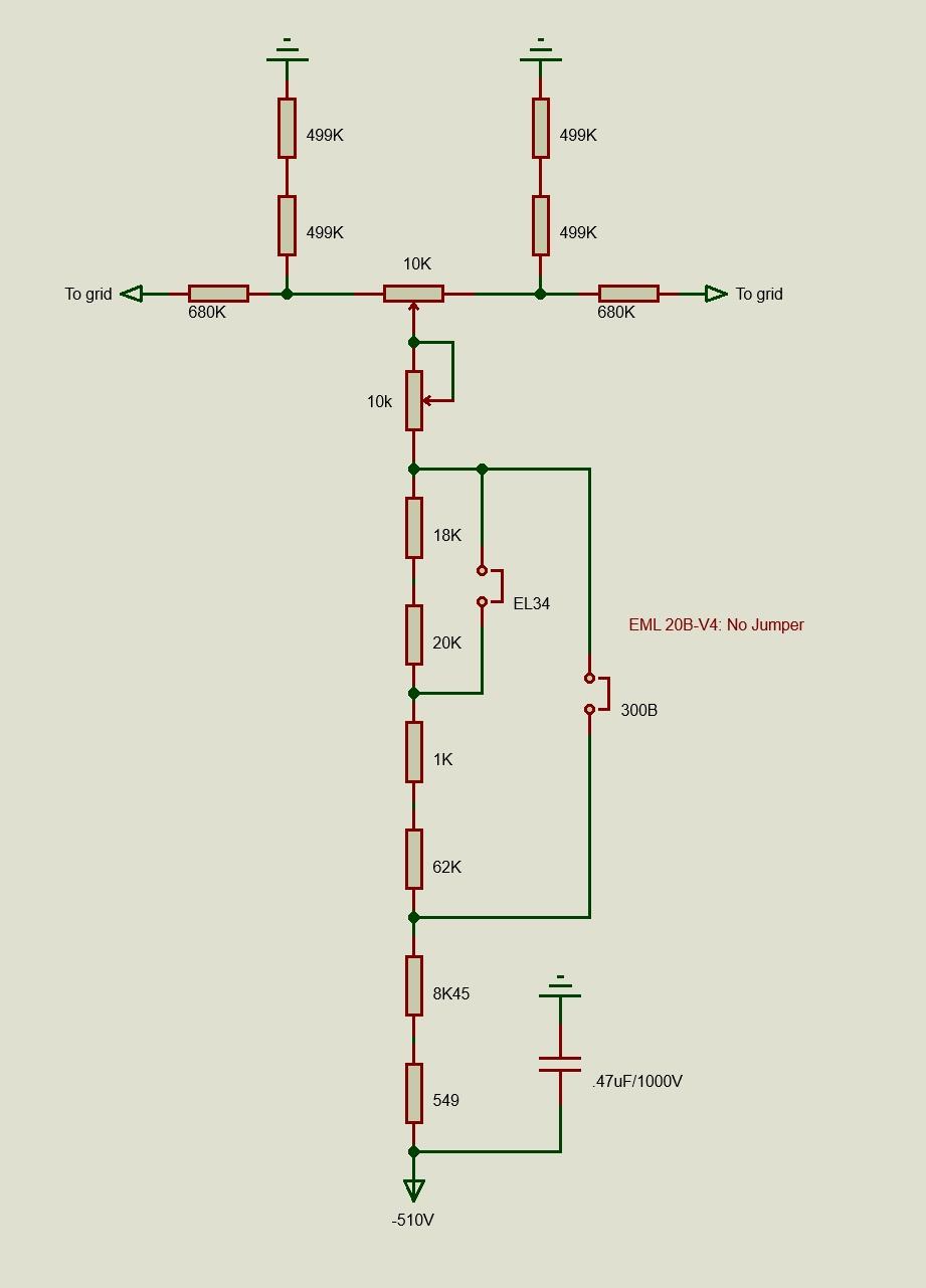
Schematics auto switching. Not sure it's accurate, but that's what I've done. New Grid Voltage Control boards. One trimmer for offset and the other for balance so, both sides are controlled simultaneously. Two jumpers. For 300B/2A3, EL34 and EML 20B-V4. Works al right, quite easy to use. The -510V is achieved with help from GRHV 110V supply. Here is one with Hammond 2VA trafo on board - 2.75in x 2in. New idea - servo controlled grid voltage. Okey, I've tried servo controlled Megatron (with solid state CCS) before and that failed...

-
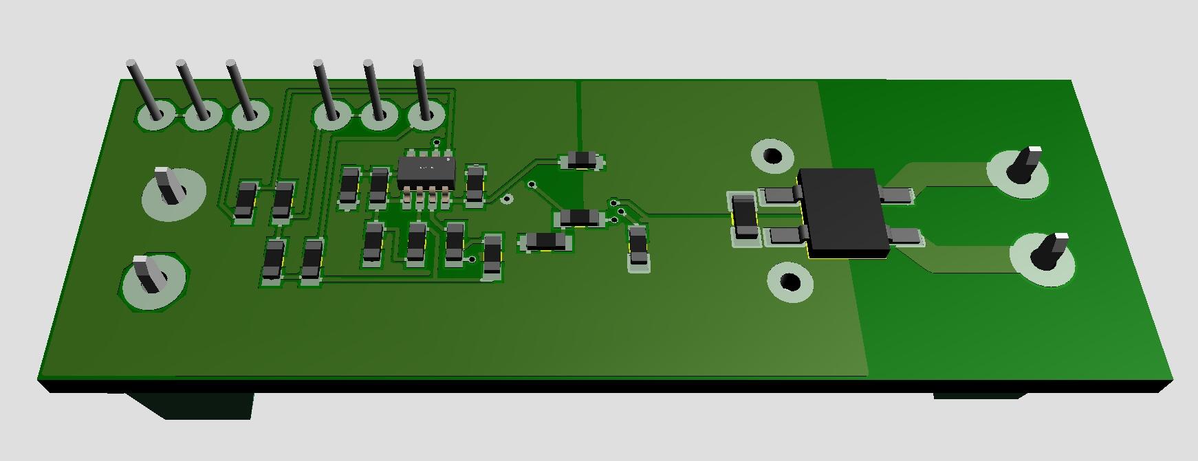
A new daughter board to my Megatron something. It sets the grid potential of the output tubes. A few resistors, one trimmer set offset and the other the balance plus a small 120V GRHV supply completes the whole thing. So, I removed cathode resistor along with its decoupling capacitor. EL34 has Vgk 40 V and 2A3 has Vgk 92 V. The amplifier has solid state CCS (no top tubes). Works? so far so good.
-
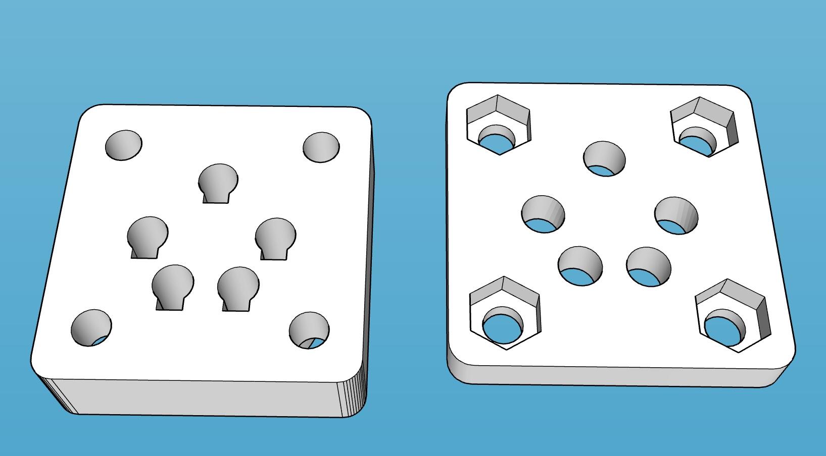
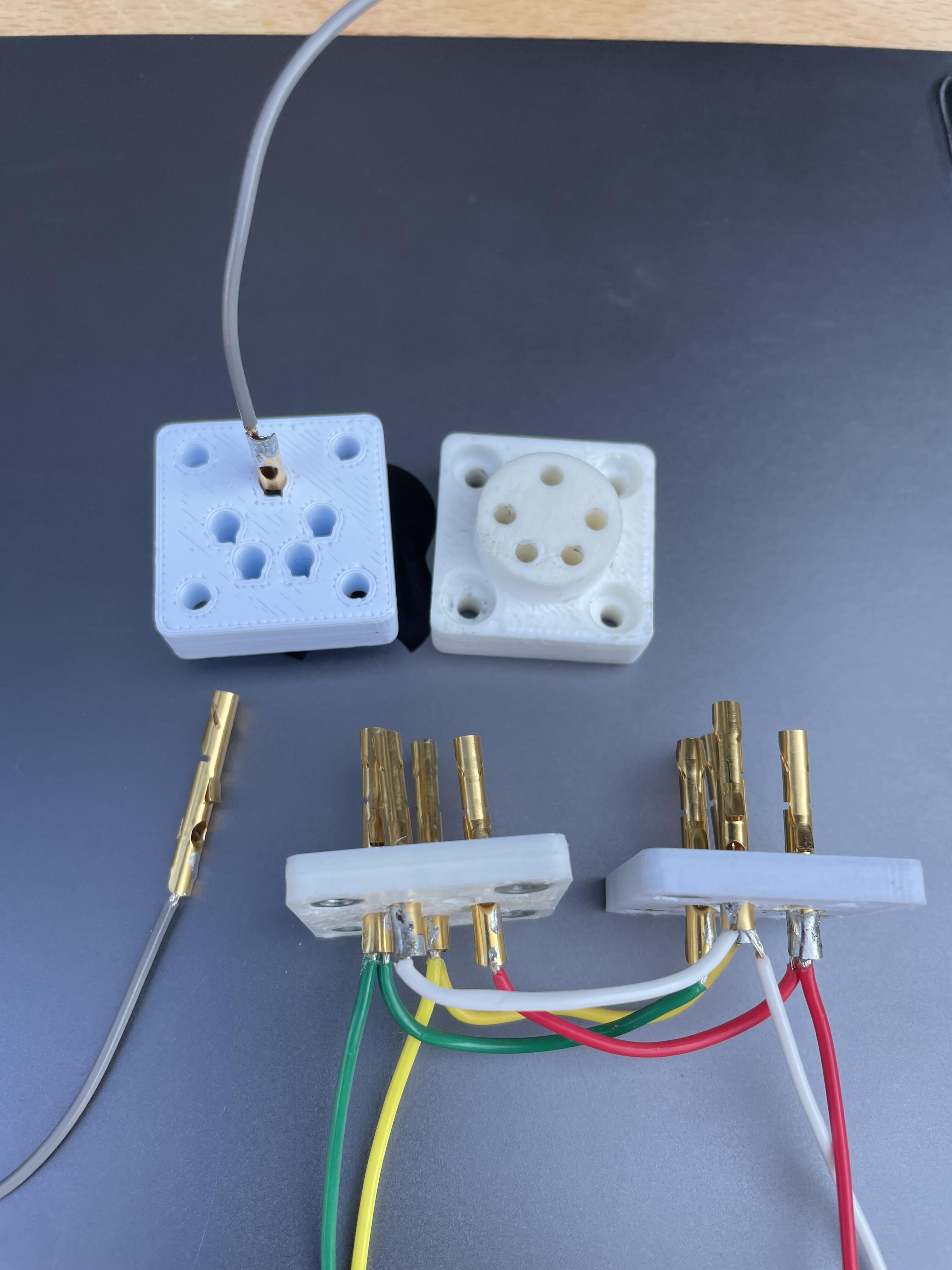
From a post somewhere else. I also tested HA-3FXX pins, but I like above pins better. Disadvantage is I had to destroy good Neutrik connectors to get the pins out. Made in Sketchup.


-
If you need 2SC4686a – check this link. German company claiming they have 4000 pieces available. I bought a couple of hundreds 10 years ago and they were genuine.
-
I bought some DC bricks from LCSC Electronics. Seems to be an all-right supplier. https://www.lcsc.com/product-detail/C2999063.html
-
Lovely, finally some use for circlotron psu. Most things settled - only finance issue… no prediction.
-
Thanks. I avoid ebay. Goods tend to be stuck or disappear in Swedish customs. Suggestions about +/-750V?
-
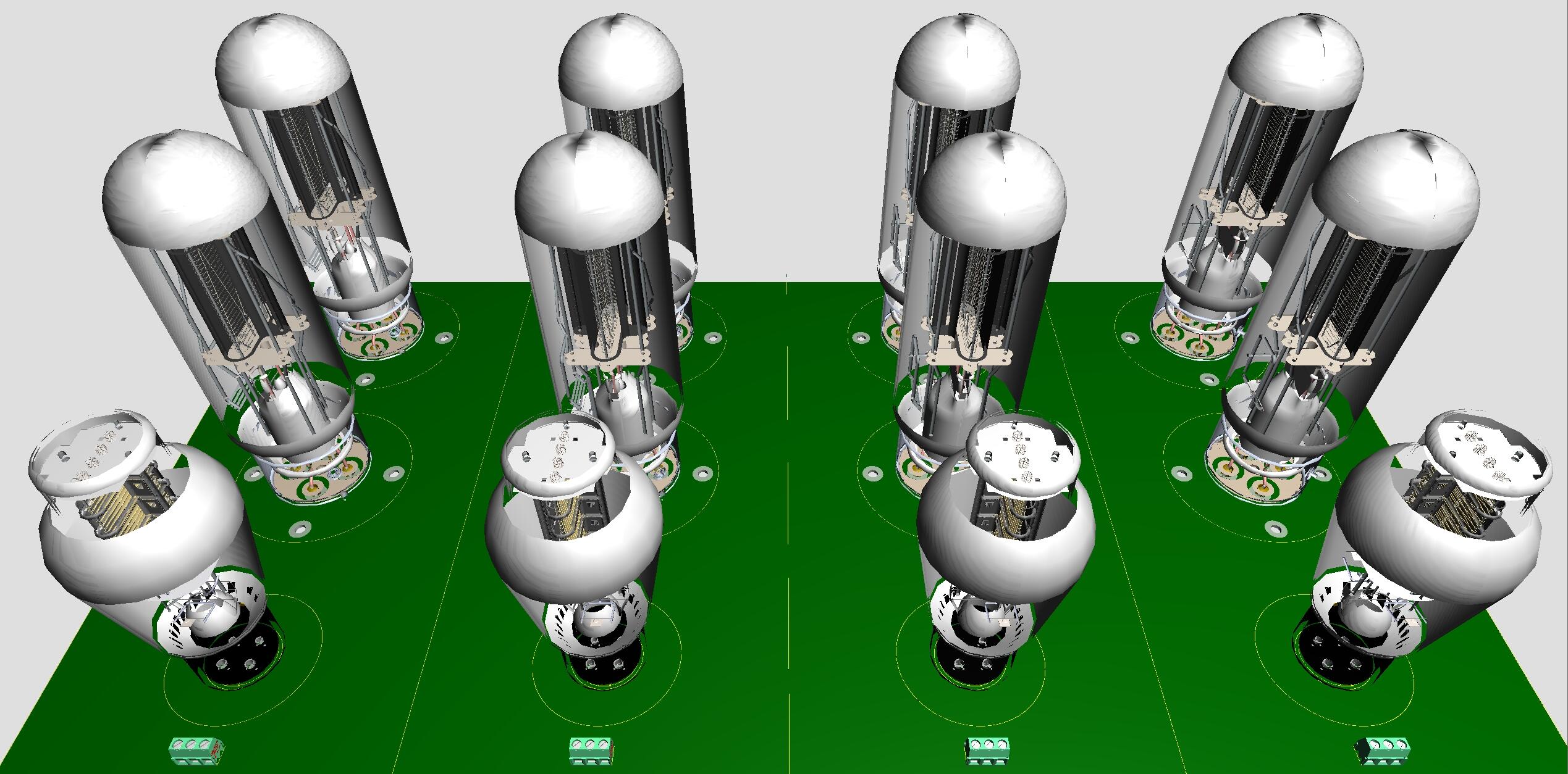
Yep, I’ve noticed output and filament boards match up to each other. Here is how it looks like on my screen, all output tubes side by side. Size 24 in x 12 in – huge. Question regarding jumbo socket – what socket do you have in mind? This from a French company might fit.?

-
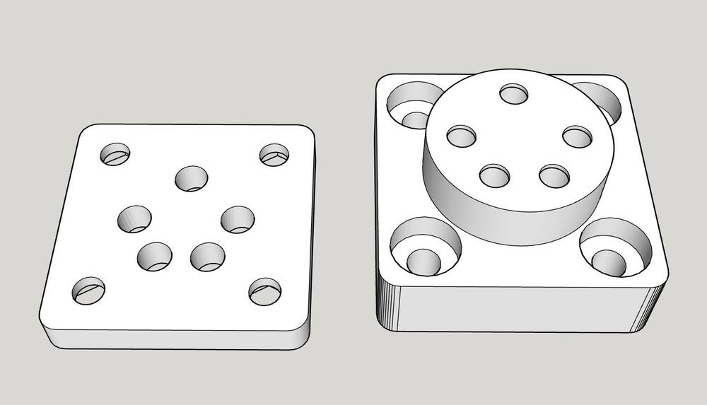
Have made schematic out of Kevin’s published gerbers of David and Goliath filament. From schematics a PCB layout following the original gerbers is made and the above 3D model is the result. I’m addicted to make my own twist of others work. So, now can the process of shrinking Kevin's board start. Just to be clear, David and Goliath project is insane. I like that.
-
Nice Omron relay 3D model, don't you think? Zoom in for a good look.