s_r
-
Posts
265 -
Joined
-
Last visited
-
Days Won
1
Content Type
Profiles
Forums
Events
Everything posted by s_r
-
How beefy of an inrush limiter would be recommended? I'm not sure these ones listed in the old BOM are quite up to it.
-
The least I would suggest is sending an angry email letter of concern to stax. Even if things are fine now with your set that's something that shouldn't go unnoticed by them.
-
At least it wasn't ants that got into the driver housing. Needless to say I'd probably be freaking out too if a headphone that cost that much squealed on me...
-
If you don't mind I'd like the link for the case as well. That's just too gorgeous.
-
Could the servo be added onto older amp boards (using a small PCB with necessary wires running to it)? I vaguely remember someone doing it but I'm not sure.
-
Most likely for my build. At extreme left I got some ground hum, so justin suggested putting in 100ohm resistors after the pot. Dead silent at both extremes now so no complaints. Might put up a pic of my kgsshv's inside a few days from now, since I reworked the wiring a bit since the last pic I have up here. Edit: Here's that pic
-
Shaping up to be quite nice there. If only my wallet would have allowed a T2 build...
-
So I take it that figure of 0.0009% THD+N isn't exactly accurate?
-
Are you going to post schematics & some measurements for the LL once all is said & done? Also, silver & amber sounds like a good idea to me.
-
I feel like kicking myself now. I had -15V hooked into the - pole instead of ground. How the LED worked for so many hours with such a dumb mistake is beyond me... Anyway, do you have any of those orange switches you were planning on getting spritzer?
-
I'm getting some weird behavior out of the latching switch on the front of my kgsshv. I noticed the LED is dimmer than it should be and decided to do a quick check with the DMM to see what's going on. Apparently I'm getting +9V/-15V (relative to star ground) instead of +12V/-12V. Really not sure what to blame here, as the switch LED crapping out on me happened once before. At least it still 'works', for now...
-
Putting in 100 ohm resistors did the trick, thanks. It's dead silent from extreme left to extreme right now.
-
I made a few changes to the inside of my HV recently. Put in the much larger encapsulated trafo and tidied up the wiring a bit. However I haven't figured out what to do with the ground hum at the pot's extreme left. Anything I should try first to see exactly where the issue is? Also SoupRKnowva, I'm not sure about pushing it past 10mAx4 with IXYS parts. It would probably drift a considerable amount.
-
The buzzing was audible with the cover on & a few feet away, so I opted for the encapsulated replacement. Quite a bit larger than the old transformer (133mm OD and 70mm height) but it makes about as much noise on as it does off.
-
Congrats on the T2, looks beautiful. Before I got a fully encapsulated replacement from sumr (old transformer was buzzing) I measured about 50-60C on the trafo in my KGSSHV. You can shoot sumr an email if you're worried, but it's not too much hotter than what I measured for mine.
-
Beats me as to what was the problem with the other board. I might put it up for sale for parts if anyone's interested.
-
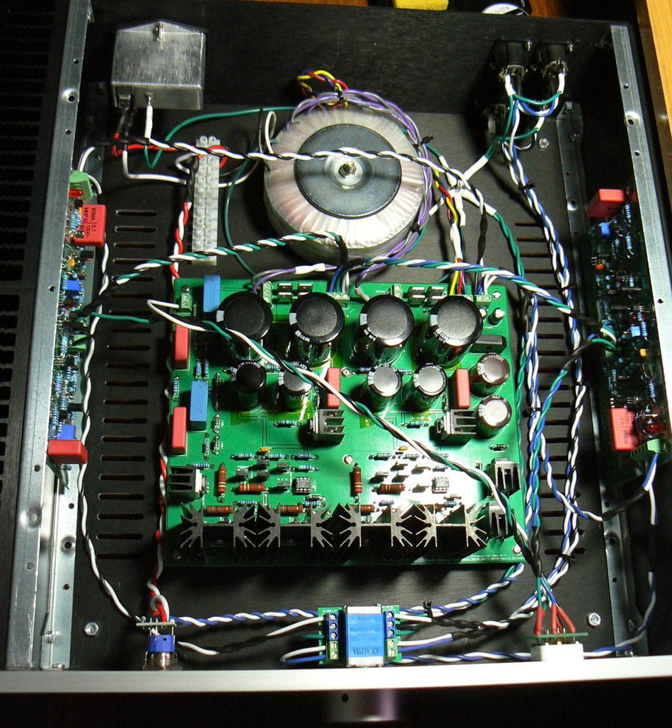
So there's one more working KGSSHV in the world. Finally received the last parts I was waiting for to finish the replacement board, and it worked on the first try. Giving it longer on-time the side heatsinks reached ~40C. I got the balance & offset on both boards to zero as well. Not that warm at all considering it's running at 10mAx4. It also makes the SRM1/MK2 look tiny. One thing though, if I turn the volume pot all the way to the left I can hear some ground hum. It's dead silent with a little turn to the right & up to max volume though. The grounding looks the same as I had it in my last internals pic (save for only one ground wire coming off the pot instead of two). This isn't just a quirk of the alpha quad is it?
-
I'm using the 1968s. So would I lower the value of the 2k resistor then (R26)? I'll probably just leave it at 10mA though, not going to be running anything but a lambda with it for a while.
-
How much output current could one really get away with for the offboard version? I actually had my working board running at ~10mA by swapping R5 and R6 with 100ohm resistors. After nearly an hour being on the outside of the heatsink reached about 37C, also the lowest I could get the offset was 7V.
-
Looks mostly the same as how I did my grounding, save for john's suggestion on the inputs and connecting the amp boards to the psu. Any reason you only used one pin on the alpha pot pcb?
-
Made the changes to the xlr inputs, hopefully the higher res makes details easier to see.
-
Yea, I have two extra since batchpcb does x2 of whatever amount of boards you order. Once I make those changes to the input grounding tomorrow I'll take a better pic.
-
I did follow an old pic of your build to ground the inputs Just attach the ground tab to one of the mounting screws for each DLX then?
-
Probably, they did seem fine when I checked them. I really don't know where the problem is so I'm just going to replace the whole amp board.
-
Well, I swapped all the sand save for the 1968s & 4686s and the board still doesn't work (same behaviour). Would anyone be kind enough to spare some 4686s? I'm building a new amp board at this point since it seems like it might be the output transistors that are the problem (or who knows what). On a positive note I've done all the wiring (feel free to point out any stupids).