mwl168
High Rollers
-
Joined
-
Last visited
Everything posted by mwl168
-
I would not recommend using 25 vac trafo for 30VDC output. The drop voltage will also vary a bit depending on current draw.
-
Hi Kevin: Other than removing the servo from the signal path, what other benefit does this added current mirror offer? And why would the SS Dynalo need it? Isn't the servo on the various Dynalo versions already out of the signal path?
-
I came to the states in 1985. Visit family in Taiwan from time to time. Always spend days and hours in 光華商場. Used to walk the isles of 中華商場 in the old days.
-
I am PISSED OFF at Mouser too. Same story, placed my order last Sunday and paid extra for express shipping. Order was confirmed within a minutes or so but was not shipped till Wednesday. I have not received the order which means it'll be Monday at the earliest. This is the same thing that happened to me twice in less than 3 weeks. I called and complained last time, Mouser could not figure out what was wrong but refunded my shipping charge. At least I did receive the shipment on Saturday. This is too much to be a coincidence. Like Pars, I've always had good experience with Mouser in the past. Wonder what's up with that company.
-
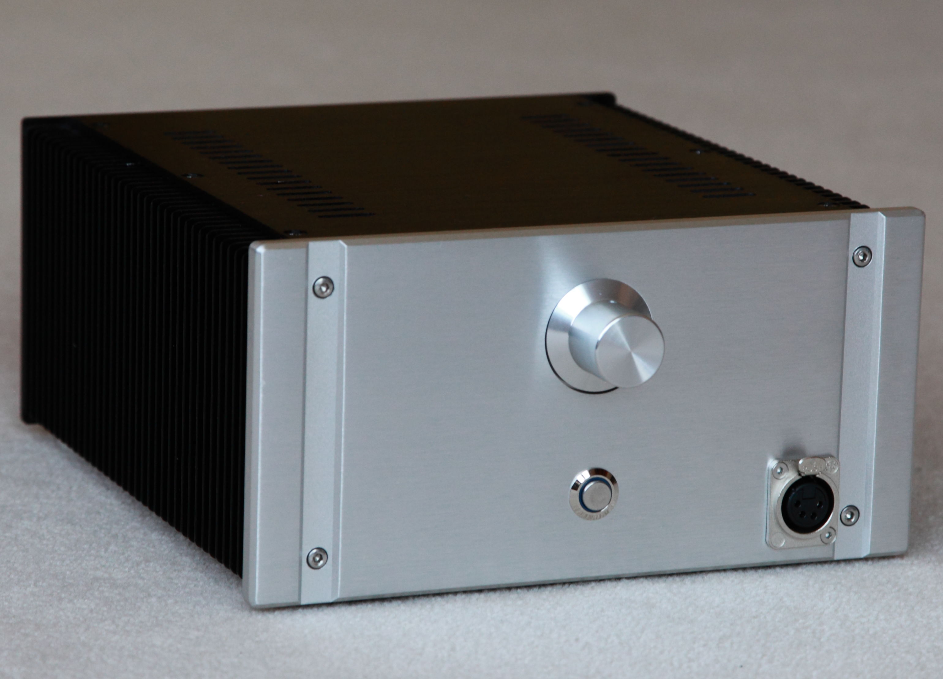
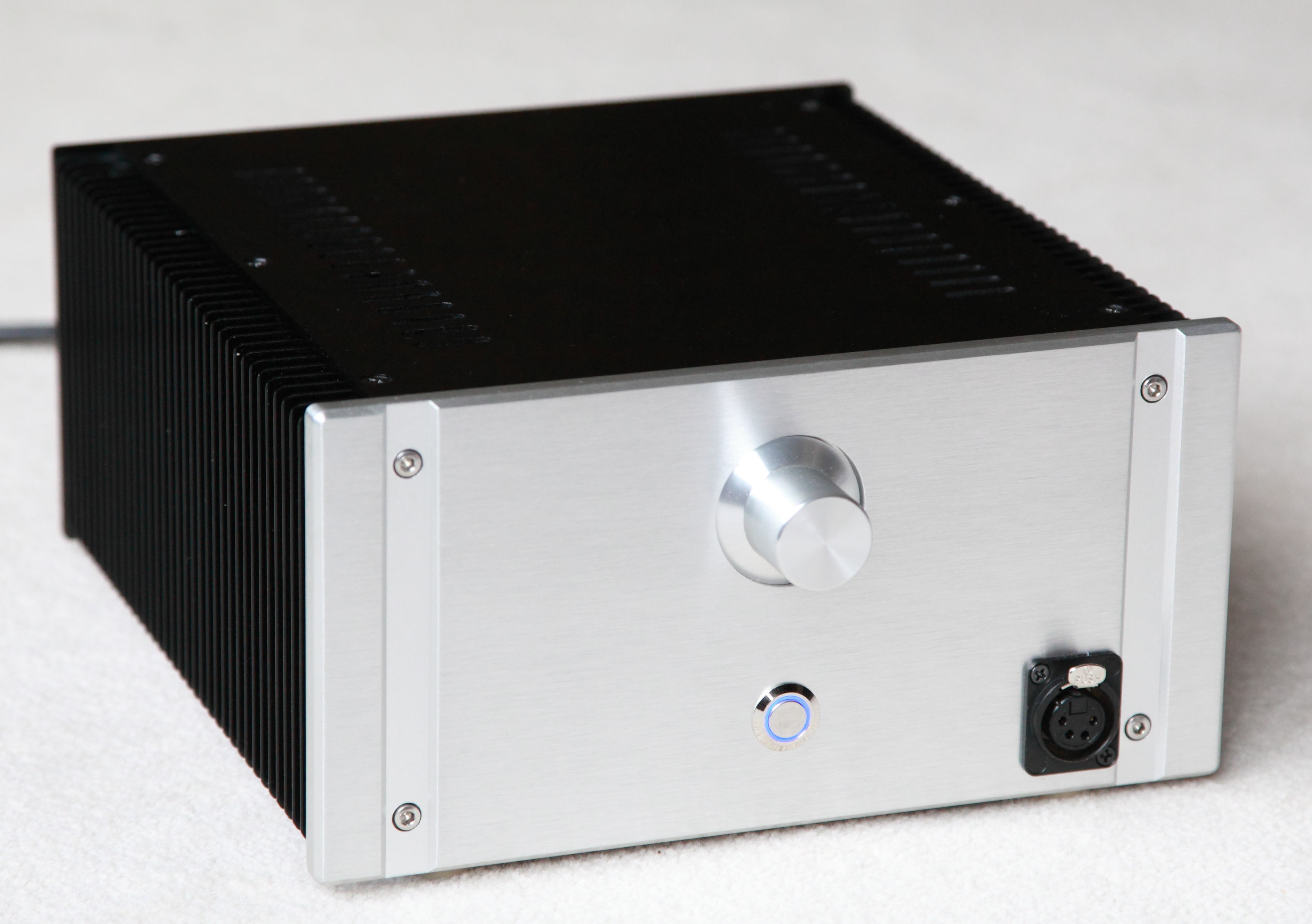
Got a shipment in and replaced the 4-pin XLR on my CFP. And, yes, it does look better to my eyes than with the black socket.
-
-
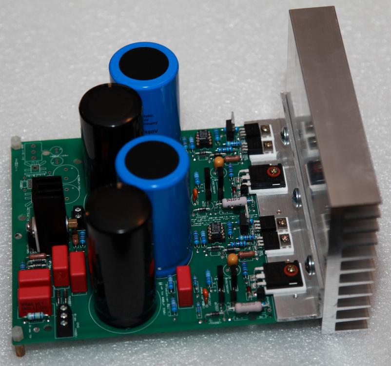
That sounds right to me - similar experience I had first time powering up the completed board!.
-
-
-
Is this offered as a kit? The PCB looks to fit the chassis perfectly.
-
I started running mine at 150mA and experimented with higher bias up to 220mA and settled for 200mA. Also experimented with supply rails from 22VDC to 26VDC. Also tried with and without the servo engaged. Frankly, in the balanced mode, I did not hear a big difference. YMMV. With servo in, the DC offset of each channel and each board is within 1mV according to my DMM. Without the servo, DC offset on each board sits around 60mV and does not change much as the amp warms up, and in balanced mode, the offset is about 30mV and very stable. I did not match the MJF output devices.
-
-
-
-
-
-
If anything, I suggest you wait till you actually loaded the PSU with the Carbon amp before you start "fine tuneing" your rail voltage. I was the same way - bugged by the "uneven" regulated voltage even though it's totally within spec of the parts' tolerance (the LT1021 and the resistors in the error amp). Actually, with 350v secondaries you will likely be able to get the rail voltage higher if you desire as long as the parts you use are rated for it.
-
Thanks guys. Just ordered the silver XLR socket and let's see how that works. I want to keep Nate happy!
-
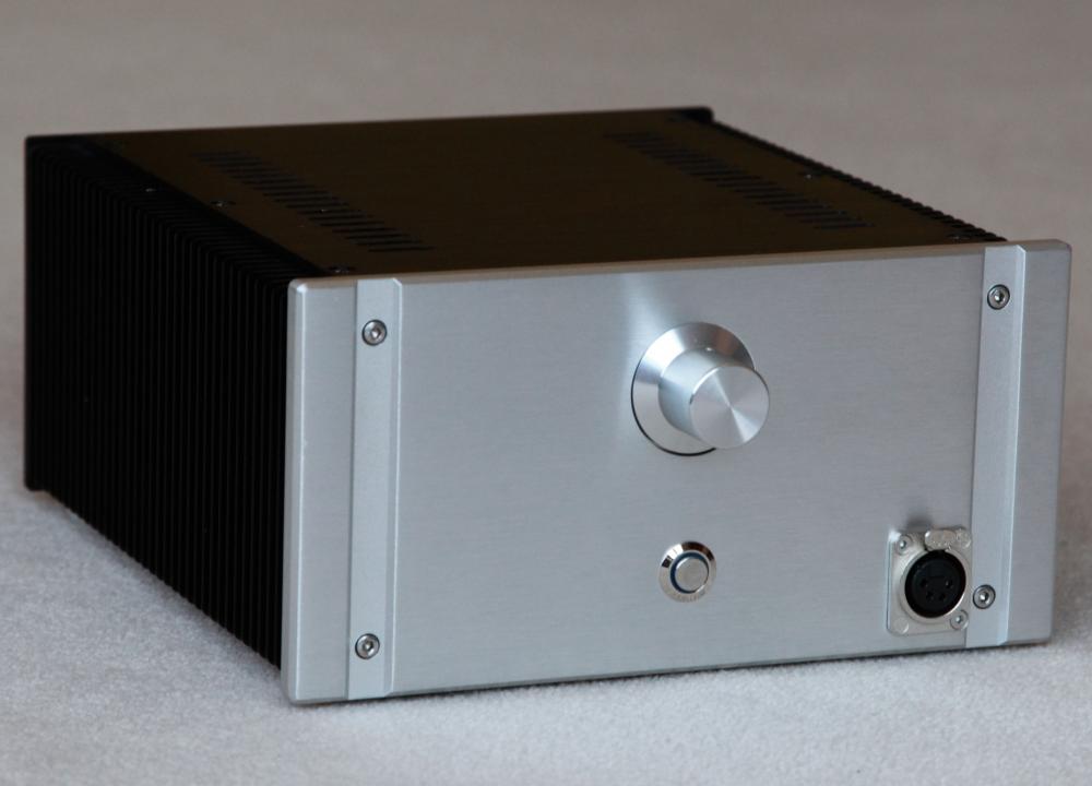
Exactly my thought Nate. Mounting behind the panel will require some recess on the back of the panel. I checked my closet but did not find a CNC router in there. Plus, it will still have the two holes for the screws exposed on the front panel which is not ideal either. It would be great to have XLR jacks made similar to Justin's Stax socket. Never scored high in the art classes I took. The black XLR socket looks fine on my silver SS Dynalo chassis but somehow looks a bit off on this particular chassis. Maybe I should put a black color knob on it...
-
Thanks Nate. On the hindsight, I wish I had ordered the XLR socket in the silver color. May still give that a try.
-
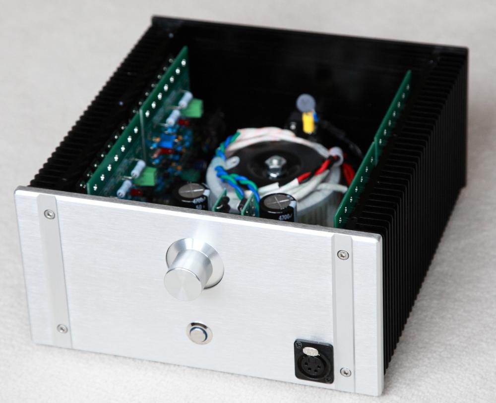
Got the XLR socket in. Here is the finished amp. The volume pot is cosmetic only - not wired.

-
-
-
I know congo5 has implemented his delay switch using this module from eBay: http://www.ebay.com/itm/DC-5V-9V-12V-Adjustable-Timing-Delay-Time-Timer-Turn-on-off-Relay-Switch-Module/191949280682?_trksid=p2047675.c100009.m1982&_trkparms=aid%3D888007%26algo%3DDISC.MBE%26ao%3D1%26asc%3D40130%26meid%3D1b0997a4bcd44fc9a34aabfdf754af52%26pid%3D100009%26rk%3D1%26rkt%3D1%26sd%3D131776109221
-
deleted - merged with previous post