mwl168
High Rollers
-
Joined
-
Last visited
Everything posted by mwl168
-
Yes, the 5K pot sets the bias current. Turing it clockwise raises the bias current. I left mine untouched from how they were shipped (my experience is they typically will sit around the middle of its adjustment range) when I first powered up. IIRC, they did not start up at anything crazy although I was only running 22VDC rails at the time. Those MJF1503x parts are 36W devices so as long as you have proper heatsink (it's a must) they should be fine. It's probably advisable to turn a pot a few turns counterclockwise before powering on to be safe. I do like the balanced setup more than I do the initial SE setup. The balanced amp seems even faster and more control. But even at its SE form, this amp was an jaw-dropper to me. By the way, have been tinkering and experimenting and I believe that, everything being equal, the bias current drift is primarily a function of the case temperature of the MJF1503x devices. As their temperature rises, the current drops. The higher the temperature variance the more the current swing. Hope this helps! EDIT: I powered down the CFP amp to measure the 5K pot setting in situ - for 210mA bias on 23VDC rails when warmed up, the pot is set around 1.8K. So I think starting up at 2.5K or higher for the 5K pot is probably a good idea.
-
The boards you have are the GRHV PSU, different from the KGSSHV PSU. The 600 R resistor and the CPC1117N are there for those that want to implement a timed delay for the HV (for the amps using tube output like Blue Hawaii) You can simply leave them out if you don't need the delay function.
-
Kevin and Birgir already answered but I am using standard silicon insulators for the GRLV pass transistors. Different story for the GRHV where aluminum oxide insulators and shoulder washes are a must otherwise arcy sparky!
-
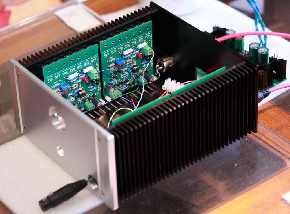
Thanks! The bias current drifts at 22VDC rails sitting in open air as well. I do think that it drifts more with higher supply rails and with all the guts in the chassis (re: higher running temperature). By the way, although this chassis makes for a compact and neat build, I would suggest using a larger chassis unless you like your amp to run rather warm. The heatsinks for the amp boards are adequate (45 C after 5 hours) but I think the pass transistors of the GRLV are putting out lots of heat - case temperature is about 55 C bolted to the bottom plate. It probably has to do with my stupidity - I am using a 28vac trafo so the pass transistors have to drop 12VDC and provide over 1A current. I should probably have opted for a trafo with 24 vac secondaries. (EDIT: I should mention that the Antek AS1228 secondaries (28 vac) sag to about 26.5 vac with this heavy load and with that input the GRLV could not sustain regulation for 28VDC rails as I originally planned. I am not certain how high a regulated output a 24 vac trafo can provide.) This amp rekindles my love for the LCD 2. Thanks Kevin for yet another great amp that seems curiously overlooked by many. And thanks to congo5 for leading me to it and all the help and advices through my build.
-
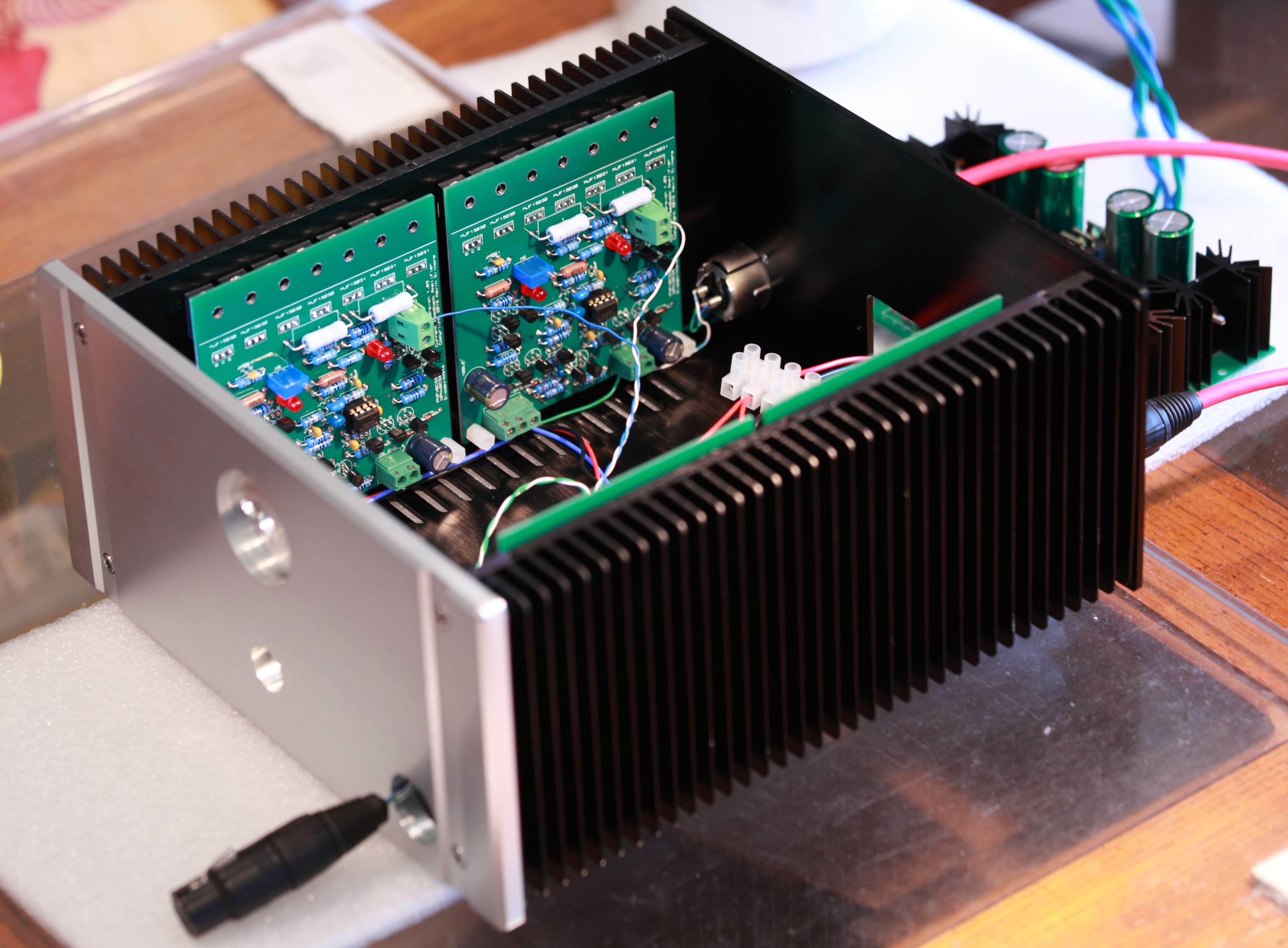
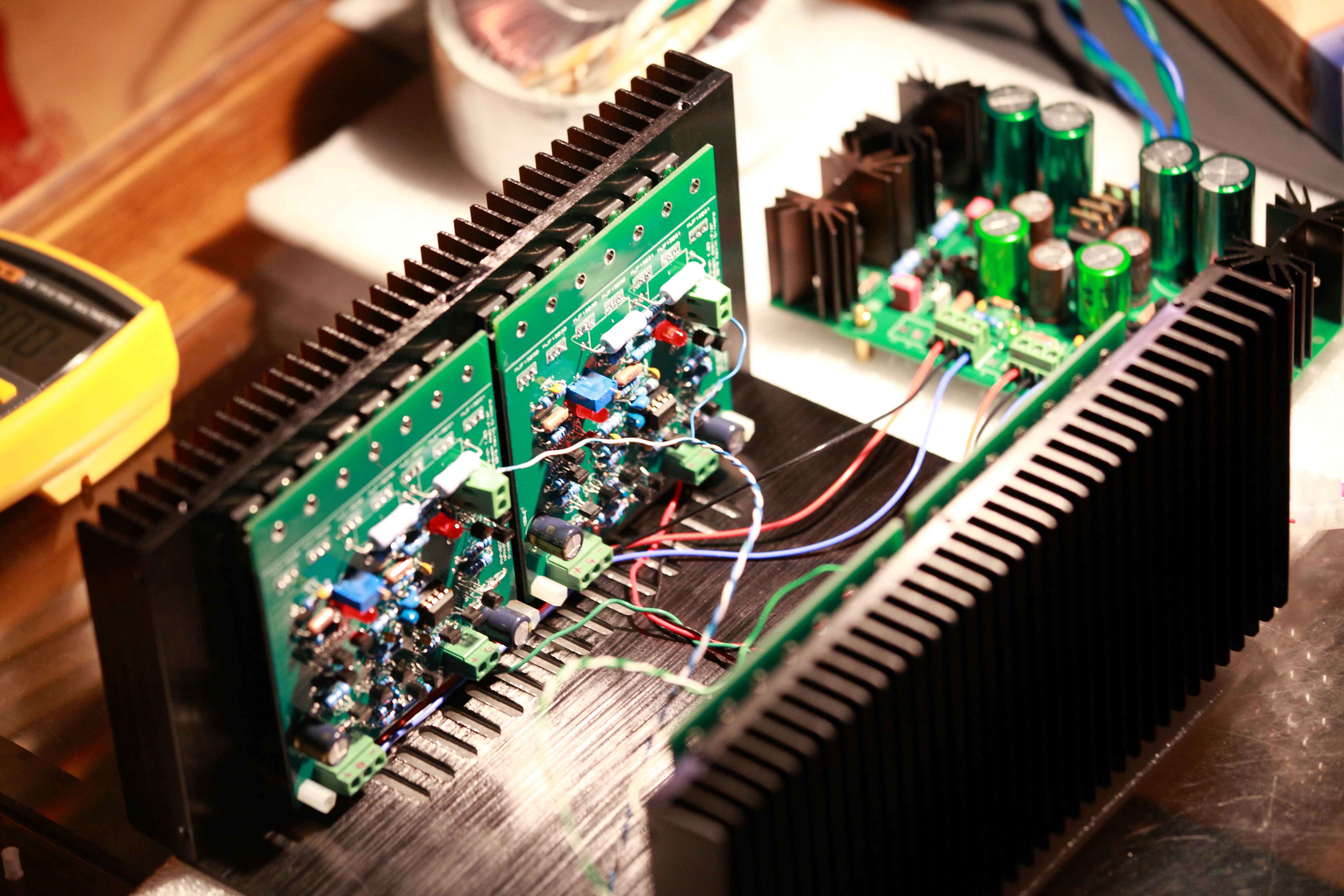
Close to finish casing my balanced CFP amp. Waiting for a 4-pin XLR socket. This one runs on 26VDC rails and 220mA bias current. I am posting an unfinished amp because I want to report that I tried OPA551 for the servo OP and it appears to work fine at less than half the cost of OPA445 but only good to 30VDC. something to consider for those that may be in the process of sourcing parts for their builds. The bias current proves tricky to dial in. It drifts downwards as the amp warms up and seem to continue to go lower even after a hour of operation. The range of drifting is significant too. I am observing 70mA and possibly higher.

-
I tried this before with my universal PSU for Blue Hawaii, Grounded Grid, etc. running on Antek transformers. My empirical experience is that a few tenth of volts is lost (measured at the filament connectors on the amp PCB) from the transformer through the umbilical, internal wiring and the PCB trace. I took out the "gizmo" I rigged together to lower the EL34 filament supply inside the PSU. My suggestion; don't do anything additional until you measure it on a running amp.
-
Yes, I do like those bridges. This pair is wider than the other ones I used for the SuSy Dynalo so I had to "relocate" the 2 10 R resistors to the reverse side of the PCB. Current draw stated is for a balanced CFP amp - 4 boards.
-
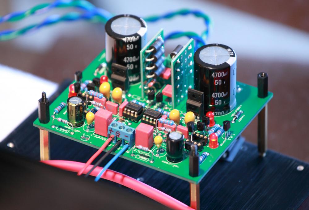
Built yet another GRLV for my CFP amp. This one set for 26VDC rails and the current draw from it is about 1.1A (for a balanced CFP amp with 220mA bias current). Empirical evidence that the GRLV can supply more than 1A current from both rails. Don't have LT1021 on hand so using LM4040 for voltage reference for now. It's much cheaper but also much higher noise. OP07 in place of OPA134. Those resistors standing tall and proud is my way of easily adjusting rail voltage while I am tinkering with the CFP amp. They are inserted into Mill-Max headers below. Cannot really see from the pic but the pass transistors are bolted to a heatsink below. EDIT: at this current draw, you need to allow for higher dropout voltage and heatsinking for the pass transistors. I would plan for solid 26vac input for 26VDC regulated rails to be safe.
-
All joke aside, although I could not find the original ad at TaoBao, I bet the "gall bladder" translation comes from that Chinese often refer to vacuum tube as "gall bladder",akin to what we sometimes refer to vacuum tube as "valve". Has been the case as long as I could remember.
-
"gall bladder" level? WTF?
-
I wonder if this depends on the design of the PSU? IIRC, Kevin's Golden Reference HV and LV are both two regulators tie together to form a bipolar PSU so measuring each rail separately seems to make sense to me. But I could be wrong about this. Maybe Kevin and others will chime in...
-
That is correct - about 1 A per rail so 2 A both rails combined if the bias current is set to 200mA. I am waiting for parts to finish the GRLV for this amp so will report back later. I am using a GRLV to supply around 1A current per rail for my DAC but it's only running 15VDC rails and it has not blown up yet...
-
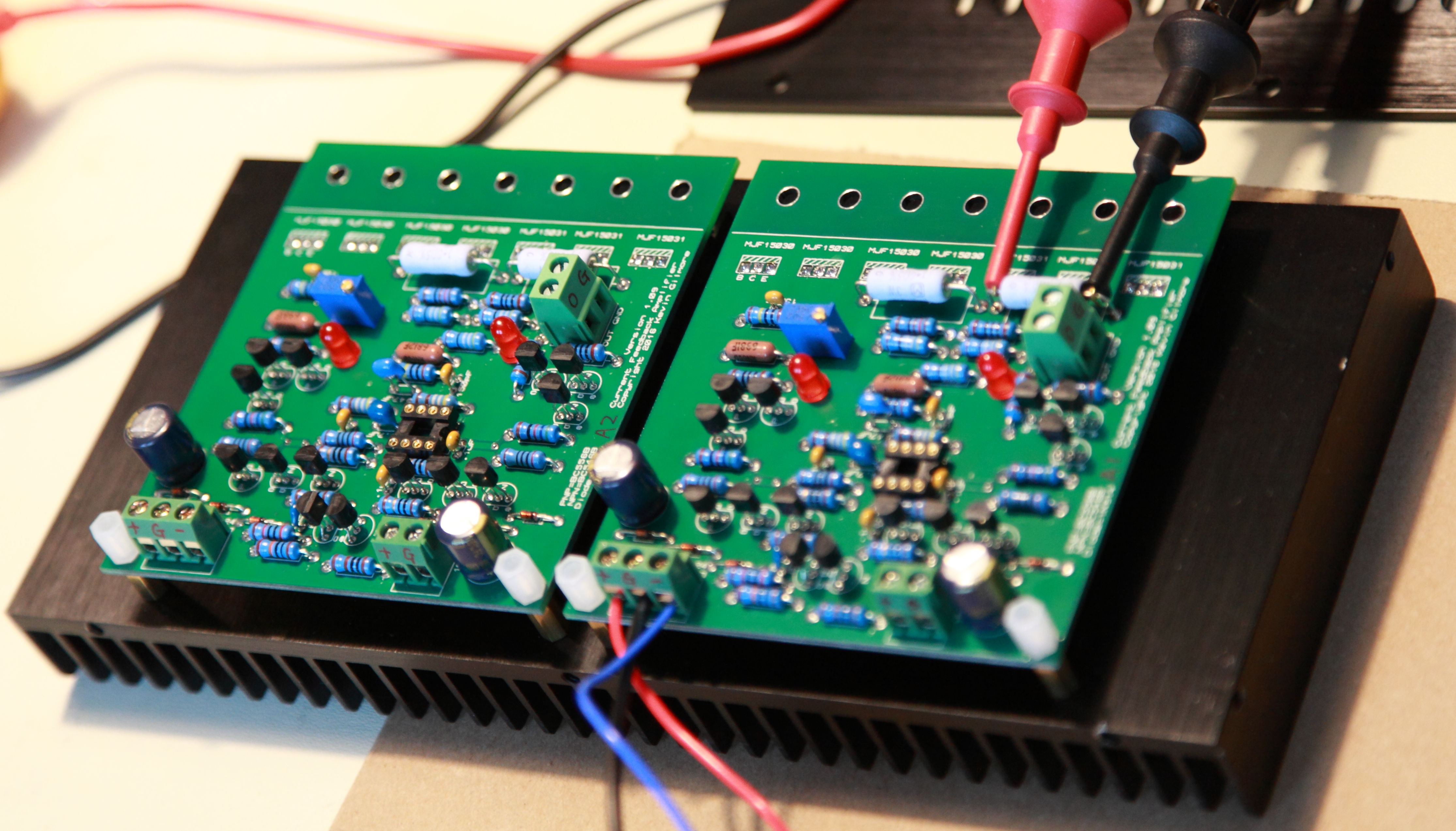
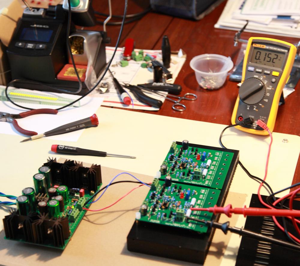
I did an empirical exercise to ascertain the current draw of the CFP amp, using a 1 ohm resistor in series between the Sigma22 and the amp boards. (My Fluke meters seem to have a hard time measuring resistance less than 1 ohm. Actually I don't even know if I can totally trust the 1 ohm measured resistance is solid.) Anyway, here it goes; with 200mA bias current, 22VDC rails and trusting the 1 ohm in series resistors are truly 1 ohm; For 4 boards combined: cold start: 1.1 A + 15 min: 988mA + 30 min: 970mA + 60 min: 963mA The + rail and - rail draw the same current. So, I think a trafo that can supply 1.5A is better suited for a balanced CFP amp. I ordered a 100VA/28v from Antek to use for my amp.
-
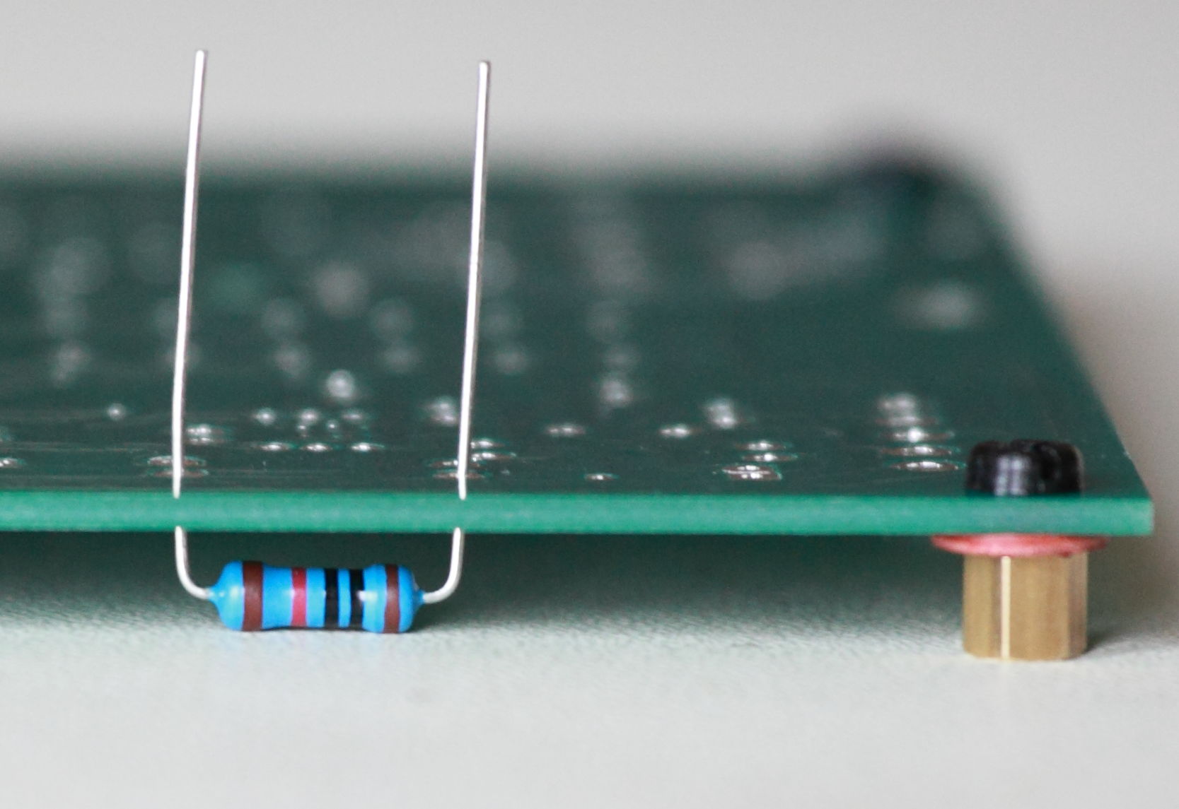
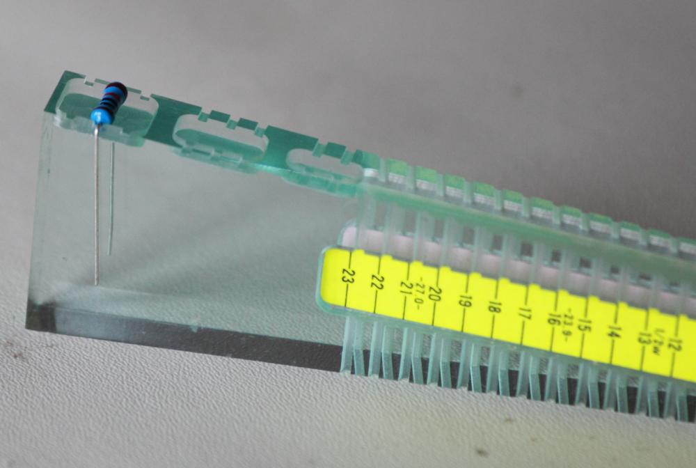
I was PM'ing with another headcaser about the practice of lifting the resistors off the PCB board for high voltage applications. I improvised a method that I have used for all my builds so far and thought I would share it here in case others may be interested. See the attached pics, I used a lead bender I bought which has a provision that works perfect for most of Kevin's layout where lead spacing for the resistors is about 11mm. To lift the resistors off the board, I put 5mm tall standoffs with a washer to make the total height about 5.5mm. This works great with KOA Speer 1/2W resistors which has a diameter of 3.5mm, thereby provides a 2mm gap between the resistor and the board. I make sure I do this on a flat, hard surface so all the resistors come out uniform height. I usually solder one lead first , exam to make sure it was not crooked, then solder the other lead.

-
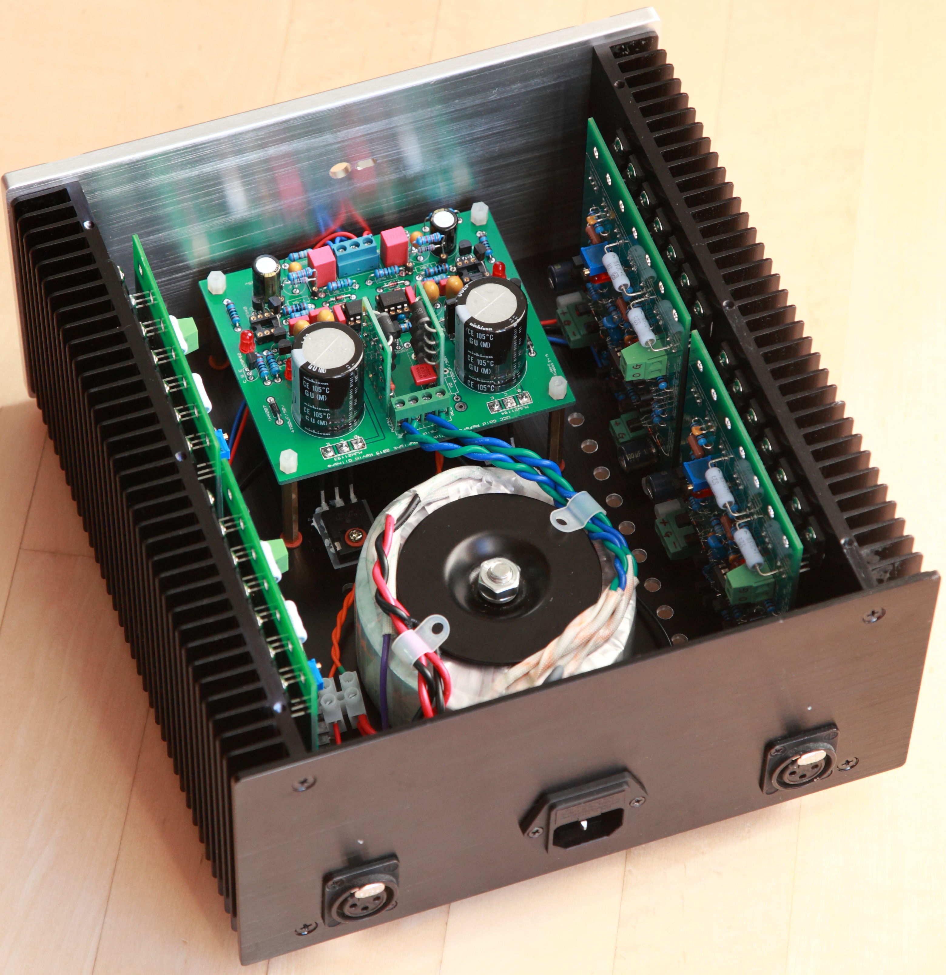
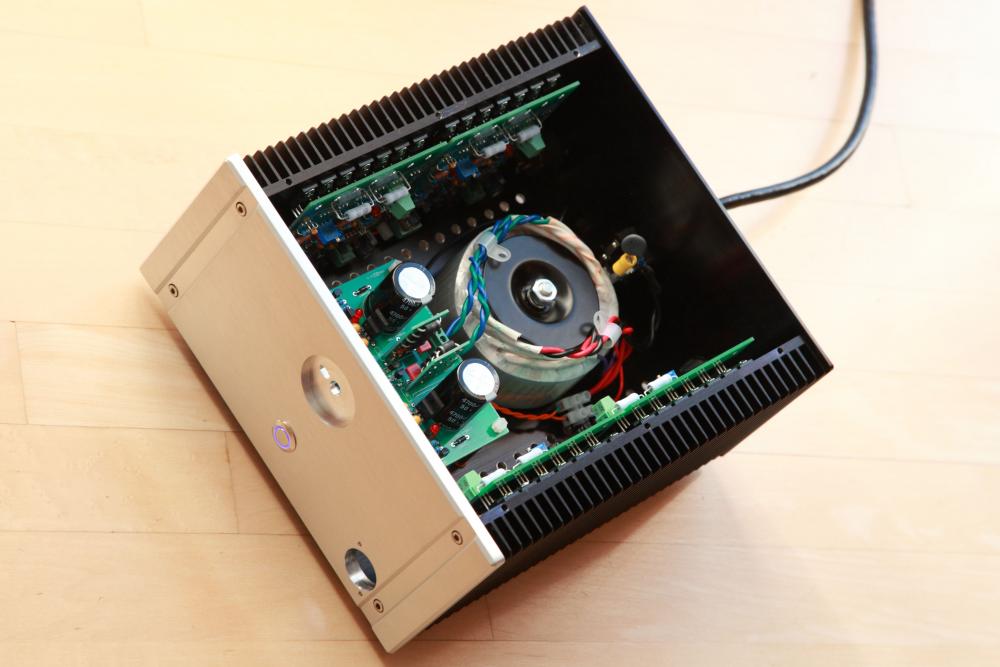
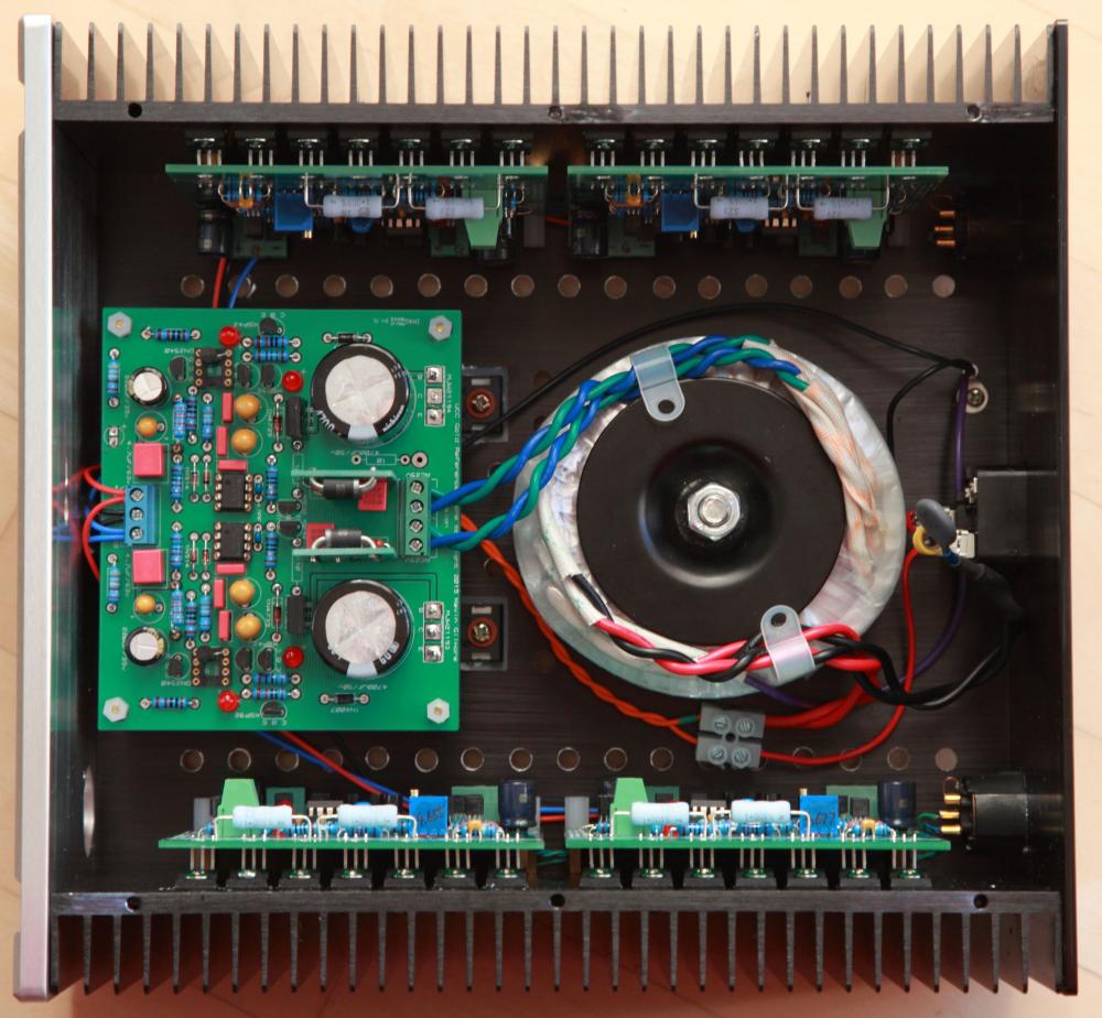
I am running 200mA bias current and 22 VDC rails now using a 200VA trafo with 22v secondaries supplying 4 boards and the Sigma 22 heatsinks are quite warm to the touch at 45 C. The Sigma 22's dropout voltage appears to be about 8-9 VDC which is consistent with the AMB documentation. If I had known how good this amp is I would have made it a full-blown, dual-mono, two chassis build with PSU in a separate chassis so I don't compromise its performance. Unfortunately the chassis I picked for it has barely enough space for a single GRLV so that's what I will do. Waiting for parts to finish the PSU and I will report back if a single GRLV is adequate to supply 4 CFP2 boards with 200mA bias current. In it's current setting, the current draw on each rail is about 850mA 4 boards combined. Here is a photo to show the chassis I am using.
-
Yes. I thought the SuSy Dynalo was powerful until I built the balanced CFP. This thing got enough power to blow my low-efficiency LCD2 to Kingdom Come. And to Kevin's other point, after some measurement and calculation and verified with Kevin, I just ordered a 100VA trafo for my CFP amp.
-
Without matching any parts other than the LEDs which I had matched for other projects, and no servo engaged, all 4 boards came up from cold start with output offset around 0.06VDC. This is without shorting the input and just rely on the 20K resistor to ground on the board. The offset does not seem to be affected by the adjustment of output bias. Once I inserted the servo OP, the offset is basically 0 V from cold start. I am using OP07 I have on hand but need to get OPs that can take higher supply rails. Did I say this amp is good?
-
Cranked the bias current to 180mA. Broke out my LCD2 as I had a feeling that this amp will be a good match for it. People with LCD2 really ought to listen to it driven by this amp at least once just for the experience. I am still in awe of the speed, clarity, resolution and control of this amp. I can understand now why Kevin said in his post that this should be the end-all of dynamic amps. This is my favorite of all my dynamic amps and I don't think it's entirely a new toy syndrome at play.
-
Yes, it's a confusing topic for me when I was obsessed with finding "The Tube" for the Blue Hawaii and the Grounded Grid. I did a lot of reading including the history of EL34 and how the beam tetrode 6CA7 came about. From what I read, GE and Sylvania wanted to produce US-equivalent of EL34 without paying for the licensing, so they developed 6CA7 as a result which is a beam tetrode and not a pentode. However, many EL34 tubes back then were also labelled 6CA7 (many actually have both designations labelled on the tube) but I have not seen a true beam tetrode 6CA7 that is also labelled EL34 so far. Many of the EL34 and 6CA7 information I read are in the guitar amp forums and many described the beam tetrode 6CA7 as a more tonally balanced tube while the EL34 is supposedly having an emphasized midrange. I decide to try the EH 6CA7 out of curiosity and that was that. I liked them so much I started to search for NOS Sylvania and GE 6CA7 quad but ended up blowing my funds in new headphone. This hobby is going to bankrupt me someday!
-
You also want to pay attention to the type of capacitor, power rating, tolerance and physical size in addition to the capacitance value. Mouser carries many options but if you want to go the exotic/boutique route such as Mundorf, RelCap, etc. you can also check Madisound, Parts Connexion, Michael Percy among other places. Some of them offer matching services which is not a bad idea for crossover parts for speakers.
-
Yes, that's the one. I may get muds on my face but I am going to say it - I have those NOS EL34 you have plus Tesla and Mullard XF2 that I've used on my Blue Hawaii and Grounded Grid. I put these EH 6CA7 on and have not felt the need to use others. It's a different flavor than the EL34 and that's to be expected given it's physically different tube. Got my matched quad from Upscale Audio so I paid more but I like the facts that Upscale burns these in for 72 hours prior to shipping so I have less to worry about defects from these current production tubes.
-
Have you considered the EH 6CA7 (the true beam tetrode ones)? IIRC, they may be a touch tougher due to larger plate structure and I personally really like their sound. They are literally a fraction of NOS EL34 price.
-
Another CFP lives. Started with a single-ended, two-board pilot, proceeded to testing a four-board, balanced setup. Have been listening to it for the past hour or so. Have to settle with 22VDC rails from a Sigma 22 owing to the limit of the transformer I have. Bias set to 150mA. Heatsinks barely get warm. Next is to build yet another GRLV for it with possibly 30VDC rails and higher bias current. Even in its somewhat compromised state, the speed, transparency and resolution of this thing is just incredible!


-
Just checked the link gepardcv posted and it clearly says "...LINEAR SYSTEMS MATCHED LSJ74/LSK170 JFET PAIRS (GRADE B)..."?
-
According to the DIYAUDIOSTORE site, that price comes with 2 matched pairs.