mwl168
High Rollers
-
Joined
-
Last visited
Everything posted by mwl168
-
I think you meant the "50R" resistor in series with the 50R trim pot in the plate CCA. If so, yes, adjust the 50R trim pot so there is 1V drop across the 50R resistor will set the CCS current at 20mA. I run mine between 18mA - 20mA at different time. I know there are others that run as high as 25mA. Make sure you have plenty of heatsink - the BH runs much hotter than the Grounded Grid does.
-
I started out using 150R instead of the 360R for the KSA1156 emitter resistors to set the current to the 3rd stage and never tried the 360R on my build so cannot comment on the sonic difference. I believe the original BH ran 10mA current to the 3rd stage and was later reduced to 3mA to reduce the heat. I decided to go half way based on a similar adjustment I made on my KGSSHV and in that case I like the sound of the raised current much better. Do note though that if you raise the current to the third stage you need to make compensation to the offset-setting resistor and trim pot. I would suggest using 1.2K or so trim pot instead of the 2K and preset it to 600R or so. You'll need to measure and do some calculation so you do not have too much voltage drop across the offset trim pot.
-
My experience echo with JoaMat's. Kevin's original Blue Hawaii schematic on Headwize stated 1/4 W resistor is fine with this part. I've used 1/2W 470R resistor in this position on my Blue Hawaii (FET version) for the past few years with no issue. This is the 100V zener I use on my Blue Hawaii. https://www.mouser.com/ProductDetail/78-BZX85B100-TAP 1.3W rated and works fine.
-
I first suspected the special diodes I am using as well but eliminate that possibility after observing the same thing with a GRLV using the regular bridge rectifiers. In this case a GRLV configured for 15VDC regulated output and fed by a 15vac transformer. It maintains regulation under load (about 300mA) and the LEDs are all lit but I was getting only 17.7VDC rectified DC at the 1N4007 and the Vce on the MLF15030 is between 2.9 - 3VDC. I do plan to use transformer with higher secondaries in the future. Your GRLV load-testing post is what prompted me to revisit this whole issue. In another case (I built quite a few GRLVs), I could not get 28VDC regulation from a transformer with 28vac secondaries when the load is over 1A and the voltage drop here between the raw rectified DC and the regulated output is over 10VDC.
-
I measured the GRLV I am using on my SS Dynalovwith transformers with 20vac secondaries. I am getting the ac input of 19.3vac under load (less than 500mA) but the rectified raw DC measured at the 1N4007 diode is only 22.7VDC and the Vce at MJW21194 is only 2.6VDC. As a result the GRLV is barely maintaining regulation for the 20VDC output, the LED s next to the MLF15030 is lit but rather dim. Ditto on the negative rail.
-
Checked 3 GRLV and observed very similar measurements. Under load, which is only 300mA - 400mA in these cases, the transformer secondaries measured right around spec. However, I am getting < 3VDC Vce on MJW21194 and MJW21193 and it seems to drift a bit, I measured between 2.3VDC - 2.9VDC at different time and the lower Vce is also reflected as dimmer LEDs next to the MJF190303/19031. I don't have the GRLV schematic on hand. What do I need to do to raise the Vce of the MJW devices to 3 - 4 VDC? EDIT: Forgot to mention that I did measure the input pins of the OP (pin 2 and 3) and pin6 of LT1021 and they all measured 10VDC.
-
So, at 2.1A draw, the regulated voltage dropped to 23.6VDC? Were the two LEDs next to the MJF1503x devices lit?
-
Thanks Soren. I will measure as suggested and report back. Since you have the same spec transformer I have (24vac, 100VA), do you mind testing it at 4.2A and 24VDC regulated output and see what you observe?
-
Fed by a transformer with 2 X 24vac/2A secondaries, my GRLV was not able to sustain regulation for 24 VDC output when the current draw was about 1A per rail. The output sagged down to about 23 VDC. The same setup works fine when I reduce the current draw to about 500mA pre rail. It also works fine for 1 A per rail draw once I lowered the regulated output to 22 VDC.
-
Have not measured the voltage drop on the pass transistor myself, but how does this 3V or 4V drop translate to the raw DC voltage at the rectifier? Drawing about 1A per rail, my GRLV could not maintain regulation for 24VDC rails when supplied by a transformer with 24vac/2A secondaries.
-
Glad to hear that you like the amp as well. Are you running a 2-board SE or 4-board balanced? For the bias, I only listened to mine (4-board balanced) briefly at 180mA. I then experimented with several combinations as high as 250mA bias and 26 VDC supply rails over a few weeks period and I settled on 22VDC rails and 200mA bias now. Frankly, I just got tired of fiddling with it and want to sit and enjoy listening to music I don't have a Dynahi so no way for me to compare. I can tell though my balanced CFA2 is significantly more powerful than my SS Dynalo.
-
@ jose: Have you tried swapping the OP's and voltage reference between the two rails to see if that makes a difference?
-
Thanks guys! I know that it's unlikely the rectifier would be the problem given Jose is getting output just not the intended potential. I should have checked before I typed... Does adjusting the negative rail trim pot do anything?
-
It's difficult for me to ascertain from the photo but those diode boards orientation looks suspicious to me. Double check and make sure the board for the negative rail is mounted correctly.
-
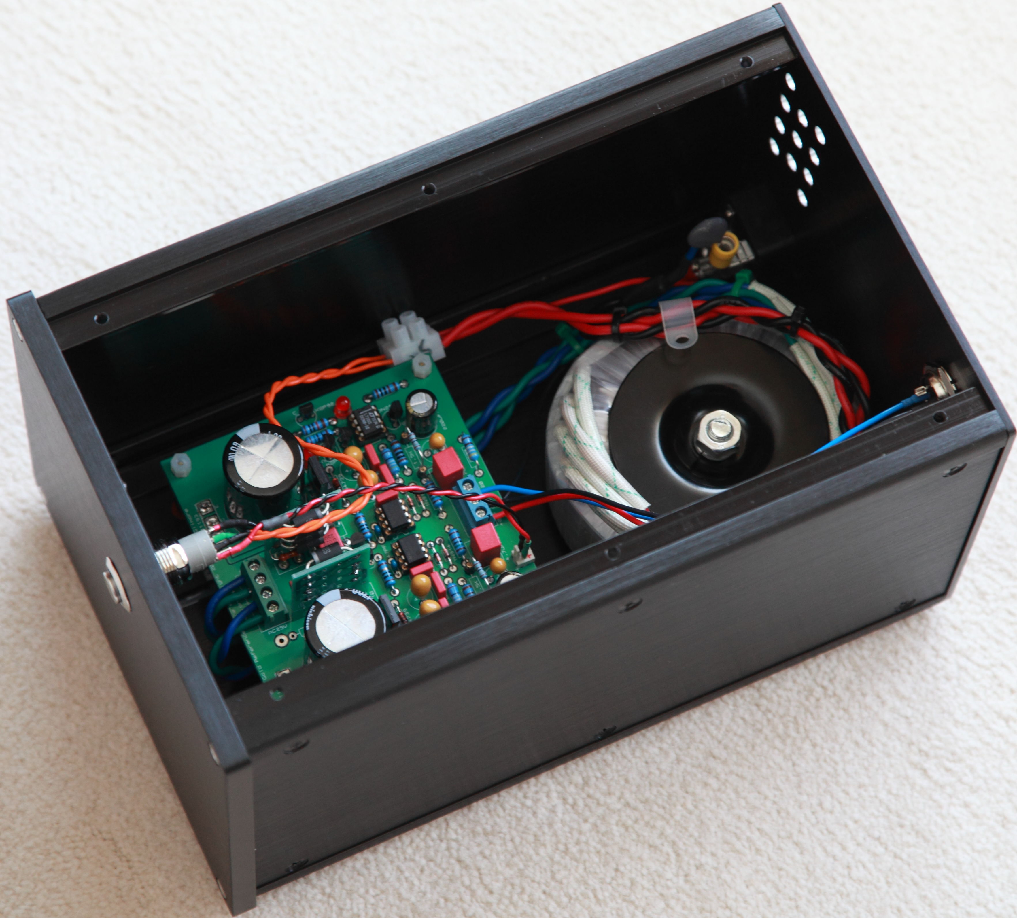
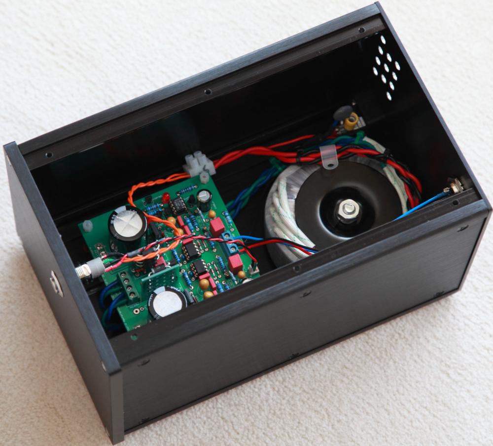
I like the CFA2 so much I want to give it a separate PSU to move the transformer away from the amp circuit. The PSU chassis came in a few days ago. Still debating if to go dual-mono with 2 GRLV.
-
Agree with cspirou that 13V drop for 20V regulated output is likely excessive. How much current does your application draw from each rails? The GRLV's dropout voltage varies with load - the higher the load the higher the dropout voltage. For my balanced CPA2 amp which I set it up to draw about 1A each rail, I have to use a transformer with 22v secondaries to support 22VDC regulated rails from the GRLV.
-
My last Mouser order was about $450 and I opted for "express" shipping.Placed my ordered on Sunday and it was shipped on Wednesday. They used to be much better.
-
I can confirm the pins MLA linked to work. I have bought these pins from the same seller on the US eBay and they work well for both the Stax headphone sockets and the octal tube sockets.
-
Looks to me that room for heatsink is the least of the problems.
-
I don't know much about watch, looking for some advice here. For an entry level watch priced around $500 with automatic movement, how would you rate between Tissot, Alpina and Frederique Constant?
-
-
-
Thanks Kevin. I posted my edit the same time you responded and I stand corrected. I got pin 5 as NC from the OP07 and OP27 datasheet but as you said, pin 5 is not NC on OPA445 and OPA551.
-
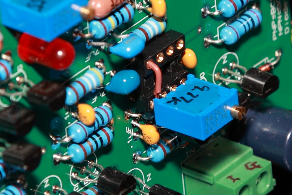
No, take a closer look at the pic I posted; I soldered a 24AWG wire to one of the outer leg of the trimpot then plug the trimpot directly into pin 5 , 6 (out), 7 (V+) of the OP socket and insert the 24AWG wire into pin 4 (V-) of the socket. The socket holds the trimpot tight and it's totally reversible. Pin 5 of OP27 is NC but is offset trim for OPA445, it's not used for this amp so the pin 5 of the OP socket is not connected to anything on the PCB.
-
I consulted with Kevin and there is an option to replace the servo with a trimpot similar to what was done on the original Dynalo. I use a 10K trimpot (10K - 20K should work for supply rails between 24VDC - 30VDC) with the wiper wired to pin 6 of the servo OP socket and the two outer legs to V+ and V-. With no input connected, I adjusted the output DC offset to 0V and it only drifts about 3mV from cold start to fully warmed up.