mwl168
High Rollers
-
Joined
-
Last visited
Everything posted by mwl168
-
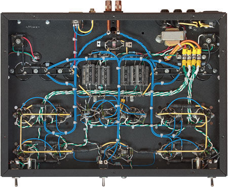
There is no reason hand-made, point-to-point wiring cannot be done right.
-
-
Here are a couple of posts in Audio Asylum from the late Mr. Charles Hansen (founder of Avalon speakers and later Ayre electronics) where he illustrated the history and inner working of HDCD. There are many more related posts you can find in Audio Asylum. I found them both educational and very interesting read. https://www.audioasylum.com/audio/digital/messages/18/184385.html https://db.audioasylum.com/mhtml/m.html?forum=digital&n=184436&highlight=HDCD+pacific+charles+hansen&search_url=%2Fcgi%2Fsearch.mpl%3Fsearchtext%3DHDCD%26b%3DAND%26topic%3D%26topics_only%3DN%26author%3Dcharles%2Bhansen%26date1%3D%26date2%3D%26slowmessage%3D%26sort%3Dscore%26sortOrder%3DDESC%26forum%3DALL
-
-
Happy Birthday, Chris!
-
RIP, Karen. My deepest condolences!
-
I am exhilarated. I have an Oppo BDP-83. Good to know it's worth $3500. Anyone interested?
-
If you are willing to shell out the cash, there are also the options of the Magnetar players... https://www.magnetarusa.com/
-
-
Happy belated birthday Kerry! Hope you had a great time.
-
Maybe try to swap the left and right channel boards and see if the hum follows the PCB board?
-
So EL34 for the CCS tubes and EMS 20B for the output tubes? Any other modifications needed other than accounting for the 20B filament supplies?
-
Apart from this audiophile scene, this is a great movie. This particular one is the second of a trilogy. The first of this trilogy is what the movie “Departed” is based on.
-
Did the PSU blow up while in play or at power-on?
-
-
Congratulations Aumkar! Quite an innovative accomplishment! Can’t wait to hear more about the INOX and to try it!
-
I’ll pm you.
-
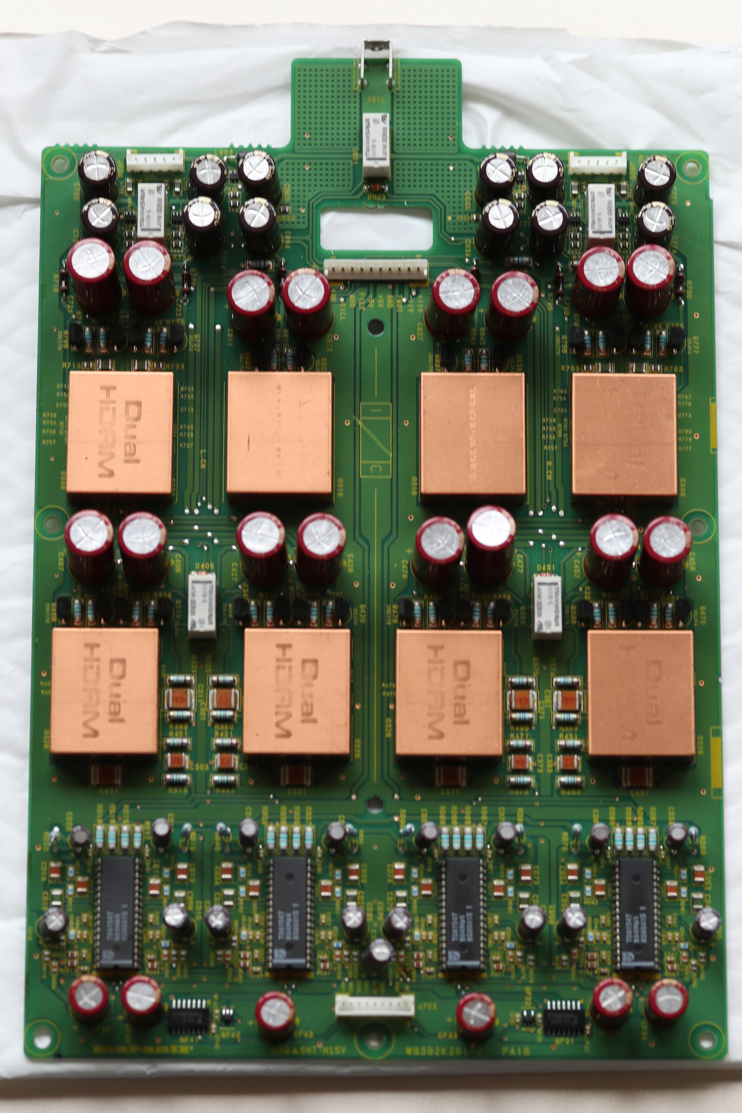
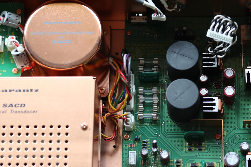
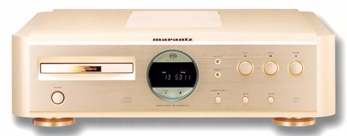
Thanks MLA and Kevin for your help. I got the player up and running yesterday first using the variac to slowly ramp-up. Later tested it without the variac and, fingers crossed, it's working fine so far. The device in question is a Marantz SA-1 SACD/CD player which uses linear power supply based on what I can see in the service manual. To expand on a long story made short, it powered up but was unresponsive when I first took it out of the box. After consulting with the service manual I dissembled the unit and found a blown fuse inside. Instead of the factory spec'ed 1A/250V slow-blow fuse, whoever last serviced the unit put in a fast-blow 2A/250V fuse. Which likely explains why it's blown upon turn-on. I replaced it with a proper slow-blow 1A/250V fuse. This is when I posted my question thinking I should play it safe given the age of the unit and suspecting why the last person serviced it put in an out-of-spec fuse. By the way, this thing is beautifully built like a tank and getting to the fuses take some work. A few photos from the web and of the exact unit. It's wonderful sounding especially with the SACD.
.jpeg.642908d20d13daeb1855642b25687179.jpeg)

-
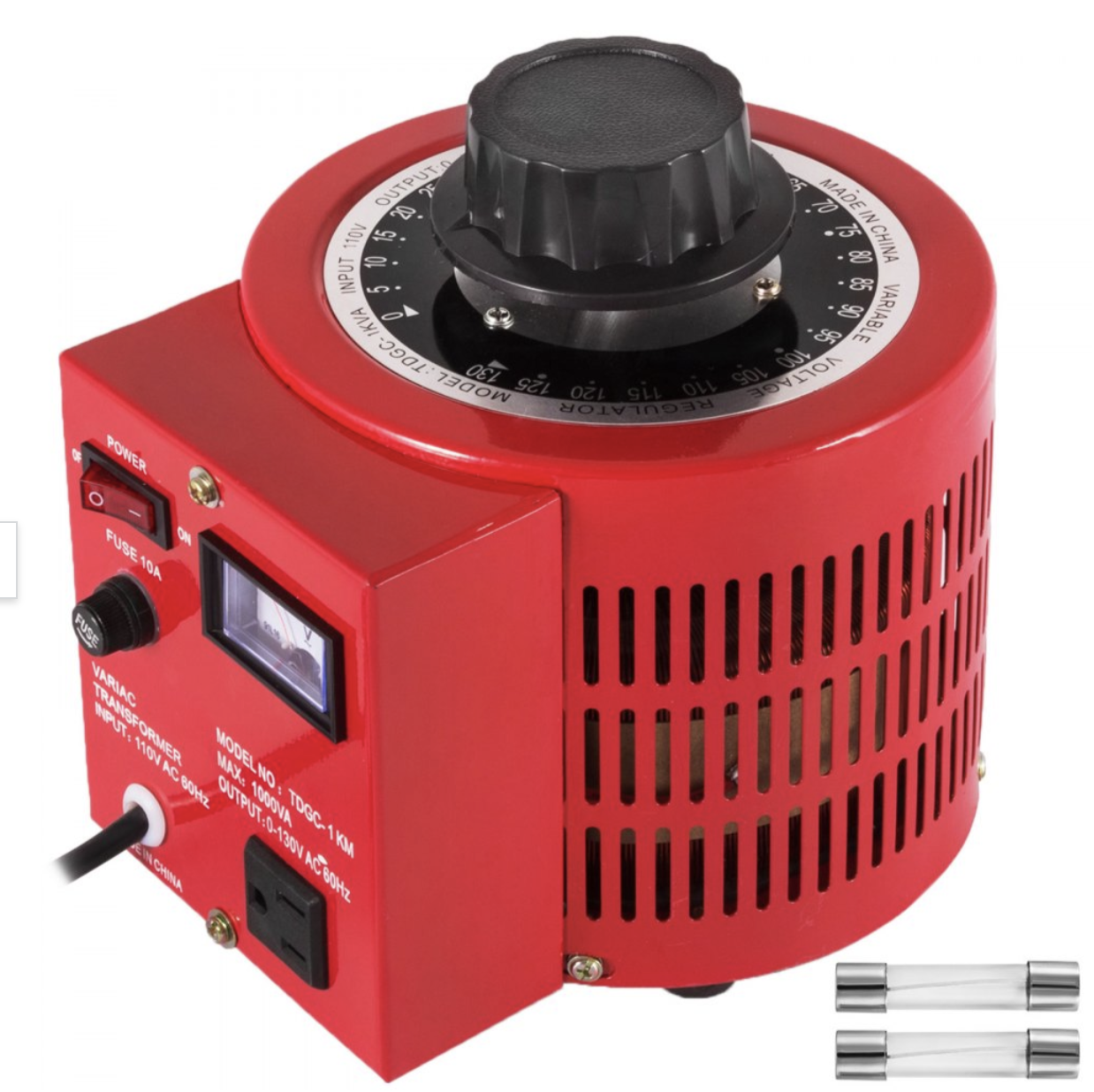
Need advice about safely powering up an all-transistor CD player that has not been powered up for many years. . I have a Marantz SACD/CD player that has been sitting in its box for many years. Is it a good idea to use my variac, like the one in the picture below. to gradually power it up? If so, what's the proper process? Thanks in advance.

-
iPhone photos while I was in Seattle for business...


-
Madison, Wisconsin


-
-
Have you considered picking up a Canon 1DX then?
-
Assuming all the removed transistors are indeed all good, this leads me to wonder if the original issue was caused by cold-soldering?
-
Nothing seems out of ordinary to me based on your description. If the offset trim pots are responding but you cannot get the offset to 0V, most likely you just need to trim the value of the resistors in series with the trim pots. I am going by memory without seeing the schematic but this information is in this thread somewhere.