


FrankCooter
High Rollers
-
Joined
-
Last visited
Everything posted by FrankCooter
-
Al, I would really appreciate your comments as well. I've got just about enough saved up for an O2, but a majorly improved ortho might make me reconsider. It's already obvious that it's going to extremely difficult to get any objective and substantive info. over on H.F. The noise content alone is overwhelming.
-
I've been thinking about getting into DIY powder coating. The professional metal finishers around here want ridiculous prices for small jobs. Looks like you can get started for about $300. Anyone have any experience in this area? I think this thread is a good idea. Half the reason I build stuff is the craft, creativity, and artistic expression that goes into i the casework.
-
Received the boards in good shape. Big thanks to Enrique, Tran, and especially Dr. Gilmore for making this happen.
-
A new (and better) source of these jacks and plugs would be greatly appreciated. My small hoard of the Amphenol jacks is pretty much exhausted. As a source of last resort, I still have a few left. But for general purposes, they're gone. In the unlikely event I ever get more, I'll post it here.
-
You do "mash it from the back", but it takes a bit of care. Try to keep the pressure even all the way around as you push so the ring doesn't get bent or broken.You'll only get one chance. I support the front of the jack with a block of wood and press the ring from the rear with a socket wrench slightly larger in diameter than the back side of the jack. Remember to keep the "teeth" of the ring pointed towards you as you push.
-
Totally ignorant and out of my league here, but since you've asked for thoughts I'll throw in my two cents. The input tubes are a good place to start. Cheap spares that have worked in another circuit are excellent for test purposes. Are the pins clean and shiny on your input tubes? I've had trouble with NOS tubes making noise because of dirty or oxidized pins. This can also happen with sockets. I'm sure you've considered this, but since the noise is common to both channels, did you scope all the power supplies, including the bias, at their outputs ? If the power supplies are clean, I'd work my way with the scope back from the output , looking at the input signal to each stage. If the noise was on one side only, I'd be thinking a bad connection or wiring error somewhere, but since it's in both channels, it's got to be something in common. Either power supply or defective components that are used in both sides. Hopefully you'll hear from somebody who knows what they're doing here.
-
Payment sent. Thanks for making this happen!
-
Beautiful work! I know from sad experiance ( 2 years as a self-employed furniture maker) what a difficult thing it is to make a go of something like this. One small idea might be to open yourself up for DIY chassis engraving. Sort of the hand made alternative to Front Panel Express. I could definitely use a service like this once or twice a year. Not enough business in the headphone community, but would certinly be attractive to the DIY sector of the larger audio world. A couple of hand engraved front panels on a Nelson Pass prototype, even if you did them gratis, might be a good way to get noticed.
-
This is exactly what I intend to do. A project like this deserves an appropriate presentation. I'm thinking something like a souped-up version of a '60's style Fisher receiver chassis and cabinet. Lots of wood and brass. Shouldn't be any problem with the on-board heat sink version .Make it whatever size is required. Once you get into it, chassis work can be as fun and creative as the electronics. Definitely don't want something that will be mistaken for a generic P.C. out of "Best Buy".
-
Very elegant power supply! Even I can now understand the "battery" sub-circuit. I've signed up for a couple of board sets, but I'm also interested in building a perf-board prototype power supply for the Egmont based amp I recently buit. Kerry, if it's no trouble, I'd really appreciate a photo of the underside of your power supply prototype. You're far neater than I'd ever be on my own. If everything works well, I'd like to try a version with 600V rails and use it to drive an amp with 801a DHT outputs. Besides zener and resistor changes, and maybe a 1KV rated pass device, anyone see any problems? I'm planning on building the version with the virtual battery, but appreciate the option of the simple zener string. My knowledge of this sort of thing is limited, but it looks to me if you eliminate the battery circuit, you've eliminated most of the error correction abiilty. Basically you have a stabilized but not regulated supply. If the battery cicuit proves troublesome, why not a simple error correction circuit based on a single 2SA1968 eq.? Thanks to all that have worked on this project, especially Dr. Gilmore. It's been an education just watching this take shape!
-
Please sign me up for 2 sets of the KGSSHV boards. Thanks to you, Kerry, and especially Kevin for all the work involved.
-
My wife works for a university engineering department. About a year ago they cleaned out the labs, tossing out a huge accumulation of "obsolete" parts. By the time I found out about it, almost everything was gone. I did manage to salvage 25 or 30 new testing RCA red base 5991 and 5992 out of a dumpster filled primarily with coffee grounds, week old lunch remnants, and half filled old milk cartons. Really needed a shower after that one. I kept a dozen or so of the red base RCA's and sold the rest on Ebay. Netted about $250. Not bad for 15 minutes of work. Still pisses me off about what I might have missed. I'm always on the look out for interesting stuff in garbage cans, garage sales, thrift stores, etc.. Used to find things on a regular basis ( Fisher 500C, Harmon Kardon Citation, Klipsch Lascala). Not much anymore.
-
For something simple, cheap, compact, with a mu of about 20, and the ability to handle 14w at 400V, a triode connected 6P14P-EV (Russian 7189/EL-84 eq.) looks very promising. Guitarists love this tube. It's built like a little tank. Out of a dozen I bought off Ebay, I put together 2 quads that biased withen a couple of mA. I'm working on an amp right now that's a further simplified version of the 7591 amp. Total cost under $200. No CCS, but 400V rails with 20mA on the finals, and a gain on paper of about 700. Solid state power supply based on an Antek toroid, a couple of Radio Daze $12.00 chokes, and some most likely counterfit Panasonic electrolytics. Chassis as tight and compact as possible. Sort of the AK-47 stripped to basics approach to functionality. "Staxes for the masses!" Sometimes it's as much or more fun to try to build something out of next to nothing as an "over-the-top" fantasy. And if it sucks, it's no great loss.
-
My amp used CCS loaded 7591's, not resistor loaded 6SN7. If you want to use 6SN7, it's probably best to stick with the original Egmont schematic that Spritzer posted.
-
Usual "rule of thumb" for electrolytic capacitor operating voltage is 80% of voltage rating. If you're running 450V rails, you are really hammering the first capacitor of the filter. In this situation I'd want at least 525V rated caps.
-
Sorry to hear about your amp Livewire. I was tempted to go to the recent San Diego meet primarily to hear it. I'm not familiar with the specifics of this design, but perhaps you'll find something useful in a few general comments. 1) Are you sure the transformer failure is a root cause rather than a symptom of another failure? Considering your previous problems with the regulator, you might want to have a closer look. How close are you running your filter capacitors to their voltage limits? After a major short, I'd probably change them. Use the highest voltage rating available. I've had issues with Ebay imports not meeting their voltage ratings. Pull the transformer out of the circuit, if it seems OK with a meter, try it with a dummy load and a Variac to bring it up slowly. If it's OK,put it back in the circuit and try a simple RC filter in place of the regulator and again bring it up slowly with the Variac. If you're OK, the problem is in the regulator, which is much more likely than the transformer. If You've still got a problem, I'd be looking for a short somewhere in the amp itself. 2) I'd definitely want both soft start and overcurrent protection in the power supply, If ordering a new transformer, I'd spec it for 3x the normal current draw if you have room in the chassis. 3) You might want to check out Antek for reasonably priced toroids. You'd probably have to stack a pair to get all the voltages you need, but you'd still be substantially under a $100. Hopefully, someone with specific knowledge will give you some better info, Good luck! Looking forward to hearing your amp at a future Ca. meet.
-
"Now I have become Death, the destroyer of worlds." - J. Robert Oppenhemer quoting the Hindu god Vishnu as he watched the explosion of the first atomic bomb. I've built my share of "Vishnu" amps and would prefer not to build any more.
-
Probably been discussed before, but any amp design with direct-coupled HV outputs makes me a bit nervous, even with a zero offset. Everything works fine in normal operation, but what happens in any given failure mode of the outputs? Is there a practical voltage limit (besides the bias) to the HV rails? This project has encouraged me to try something a little more ambitious. I'm considering something similar but with direct- coupled 801A DHT outputs. This would require 600V rails. Any additional safety issues involved?
-
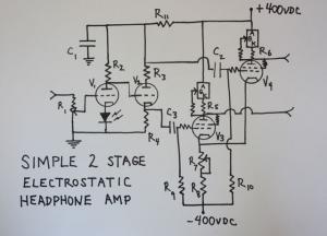
All R7 does is give some adjustment to R8. Maybe I'm missing something, but I don't see that it matters if R7 is either above or below R8. Together R7/R8 form the cathode bias resistance for the push-pull 7591 outputs. Unlike the usual arrangement of this type, R7/R8 do not set the plate currents in the push-pull pair, in this case the plate current is set by the 10m90 cathode resistor. Varying R7 moves the plate voltage of the 7591 pair up or down in relation to ground. Ideal plate voltage to ground (the offset) is 0V. I originally tried a LTP as the first stage. It wasn't stable and would blow the regulator pass transistor, the associated zener string, and the filter capacitors of the positive rail. The regulator had no problem with a dummy load. Getting rid of the LTP cured the problem, but at this point I went with a simple CLC filter to avoid any further issues. As drawn, your design won't work because it will put the DC plate voltage directly on the headphones. If you added coupling capacitors to the output it would be OK. The whole point of the bipolar HV supplies is to allow for direct coupled output by setting the plates of the output tubes at 0V in relation to ground. K.G. and Spritzer would be the sources for a better explanation of this type of circuit.
-
The drawing is incorrect. The grid of V4 should be connected to the plate side of R3. Thanks for spotting the mistake!
-
Here's a list of component values for the 7591 electrostatic amp. None of these values are optimized in any way and mostly reflect what I had at hand. As much as possible, i tried to use I tried to use "bang for the buck" bottom-feeder components. V1/V2: 6SL7 dual triode. '50's Sylvania are still around at decent prices. Cheaper would be a 12AT7. V3,V4: 7591 power pentode run in triode mode. 7591's are expensive and rare in NOS. I was lucky to have pulled some out of a garbage bin years ago. J.J. and E.H. make new ones that run about $75.00 a quad. A cheap substitute would be the Russian 6P14P-EV, which is an uprated EL84. Without individual cathode pots, each channel should be a balanced pair. R7 sets the offset, which should be as close as possible to 0V. CCS loads for 7591: IXYS10m90 current sources. Be sure to use good sized heat sinks. Set R5 current set resistors for 20mA, which is about 150 ohms. R1: 50k/100k audio potentiometer. R2:220k, R3,R4: 120k, R5,R6:150 ohm, R7:200ohm 2 w linear pot, R8:470 ohm 5 or 10w. R9,R10: 500k, R11:16k 2w. Stopper resistors on CCS gates are 1k. Stopper resistors on 7591 grids are 330 ohms. Triode connection resistors on 7591 screens are 100 ohms. C1: 450V electrolytic, value not critical C2,C3: .22@600V. I used the excellent but cheap Russian K-40 PIO . Power supply was based on an Antek dual 325V toroid with cheap "Radiodaze" chokes. Filter caps were 220@450V Panasonic electrolytics off Ebay. Chassis is whatever you want. Mine was leftover materials from another project. Surplus Sales of Nebraska has something called a "Nabu" (sp?) that sells for about $20.00. Total costs, not counting chassis work, run about $225. if you use a 12AT7/6P14P tube component. Add another $100. for a 6SL7/7591 tube complement. My long suffering wife calls this the "Everyman's Amp" because it's the cheapest thing I've built in years. Definitely a fun and worthwhile project. Because of the voltage levels, it's not a beginner project. High voltage safety procedures should be understood and utilized when constructing any project of this type.
-
Here's the resized schematic. Hope the second time's the charm. If anyone's interested, I'll do a detailed list of component values. I like the 6SL7/7591 combination, but a 12AT7/7189 combo would probably work just as well, and if you used the Russian 6P14EV, would be dirt cheap to implement. Power supply can be anything you want. I started with solid state regulators, but after blowing the pass transistors a couple of times, I replaced the regulators with simple CLC filters. output caps are motor-run PIO, and eventually I'd like to experiment with Schotky rectifiers to see if it makes audible difference. Running straight AC on the filaments, but still sounds dead quiet.
-
Screwed up the sizing of the schematic so I pulled it. I'll put it back up tomorrow. Only thing worse than my photography is my internet ability. Please excuse my incompetence.
-
Here's a simple little tube electrostatic amp that started out as an Egmont. The output stage, formerly a pair of resistor loaded 6SN7's run at 300V, is now a pair of triode connected 7591's with IXYS10M90 CCS plate loads run on 400V rails. The original 12AX7 based "long tailed pair" first stage was unstable with the 7591 CCS loads. I replaced it with a simple 6SL7 based Williamson type circuit and all was fine. Total costs are a bit over $200.00. Sounds surprisingly good!
-
Beautiful gesture and beautiful work! Wood turning is a distinctive art and skill all its own that even most accomplished woodworkers avoid like the plague. Years ago I spent an unsuccessful month trying to learn. Congratulations on a job well done!
