JoaMat
-
Posts
1,545 -
Joined
-
Last visited
-
Days Won
16
Content Type
Profiles
Forums
Events
Everything posted by JoaMat
-
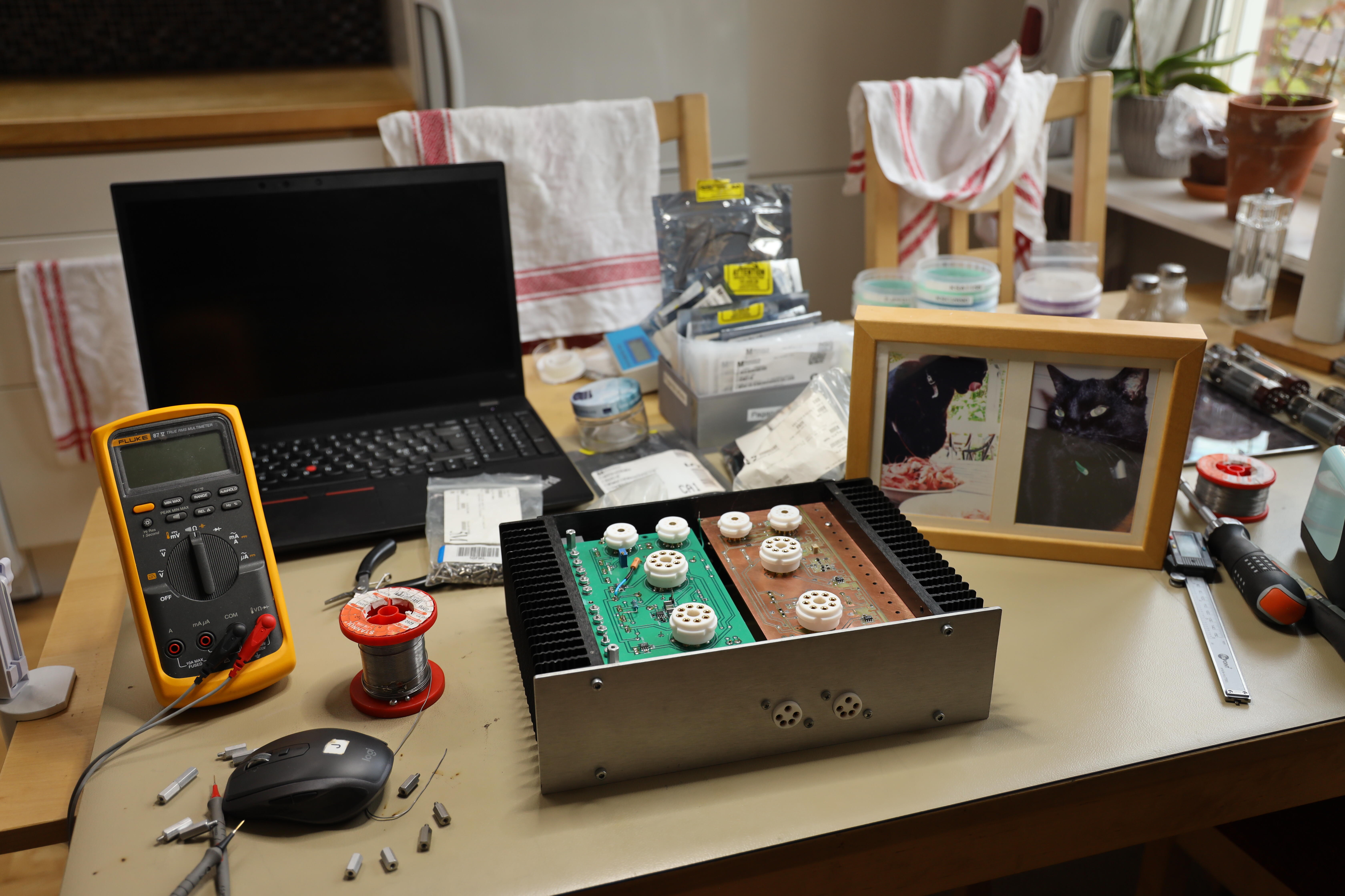
Kitchen in a terrible mess. The fellow in black is Pepsi and he loved schrimps. RIP.

-
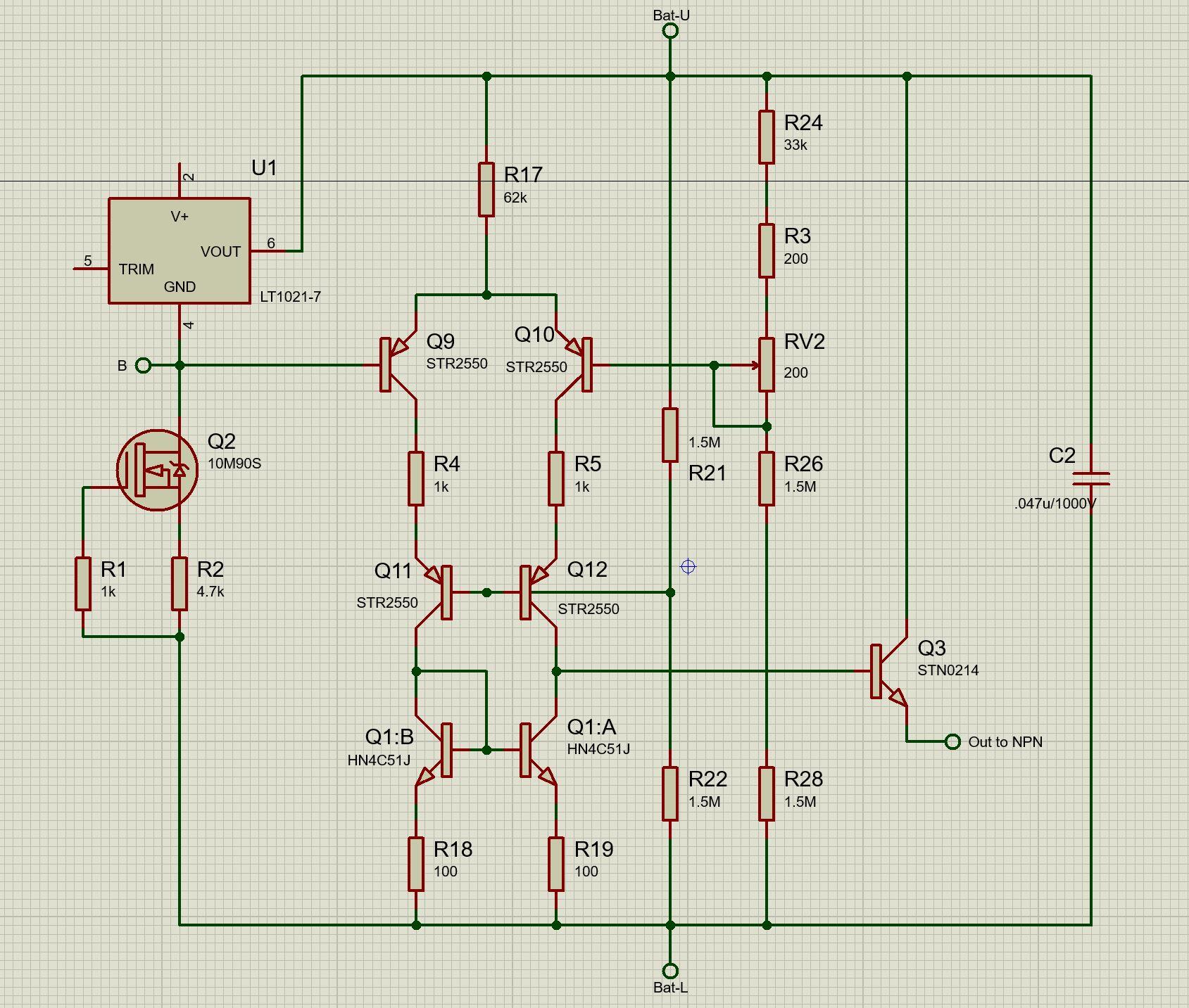
Thanks, BUL216 added as c3675 substitute candidate. Here is a schematic of latest battery module if interested. R2 sets current through the voltage reference. R2 = 4.7K gives roughly 0.9mA. With 4.7K Q3 is needed if NPN is FJPF2145. If NPN is 2SC3675 Q3 is not needed. If R2 is 2K then roughly 2mA. Then Q3 is not needed for neither 2SC3675 nor FJPF2145. Purpose of R4 and R5 is to determine current through Q9,Q11 and Q10,Q12. With Q3 I measure roughly 0.05mA through both sides. Without Q3 almost all current goes through Q10/Q12 and if not enough the desired voltage can’t be regulated and that is what happens with FJPF2145 while 2SC3675 works but it’s very close…
-
No, fjpf2145 is not a direct replacement for 2sc3675. 2sc3675 is a 900 V device while fjpf2145 is good for 800 V. I’ve used fjpf2145 in all c3675 positions on T2 except for Q8-10 and Q13-15 (output current sources). But if you decrease to +/-400V I guess you can replace c3675 with fjpf2145 here as well. I’ve also replaced c3675 with other transistors than fjpf2145. For instance Q30,31 with 2sc3324, a sot23 smd part. Might pop up in a future mini T2 with active battery...
-
There are only a few modern npn alternatives to c3675. One is fjpf2145 which I’ve used since several years. In my modified T2 the fjpf2145 work alright with its batteries. The battery I’m trying now drives c3675 but not fjpf2145 without stn0214 in a Darlington pair. With stn0214 in the battery you can use whatever npn you like c3675, c4686, ksc5026 or fjpf2145. So for time being I don’t consider stp03d200, but it will certainly work.
-
Just removed stn0214 (the sot-223 device mentioned above). The npn I use on test board is fjpf2145. It has lower hFE than 2sc3675 and battery on test board is not capable to drive the fjpf2145 alone, it needs the Darlington pair. For reference, https://www.head-case.org/forums/topic/6837-the-ultimate-diy-a-stax-srm-t2/?do=findComment&comment=419666 , here Kevin wrote about darlington out of a pair of 2sc4686. I believe hFE for 2sc4686 is even lower than for fjpf2145.
-
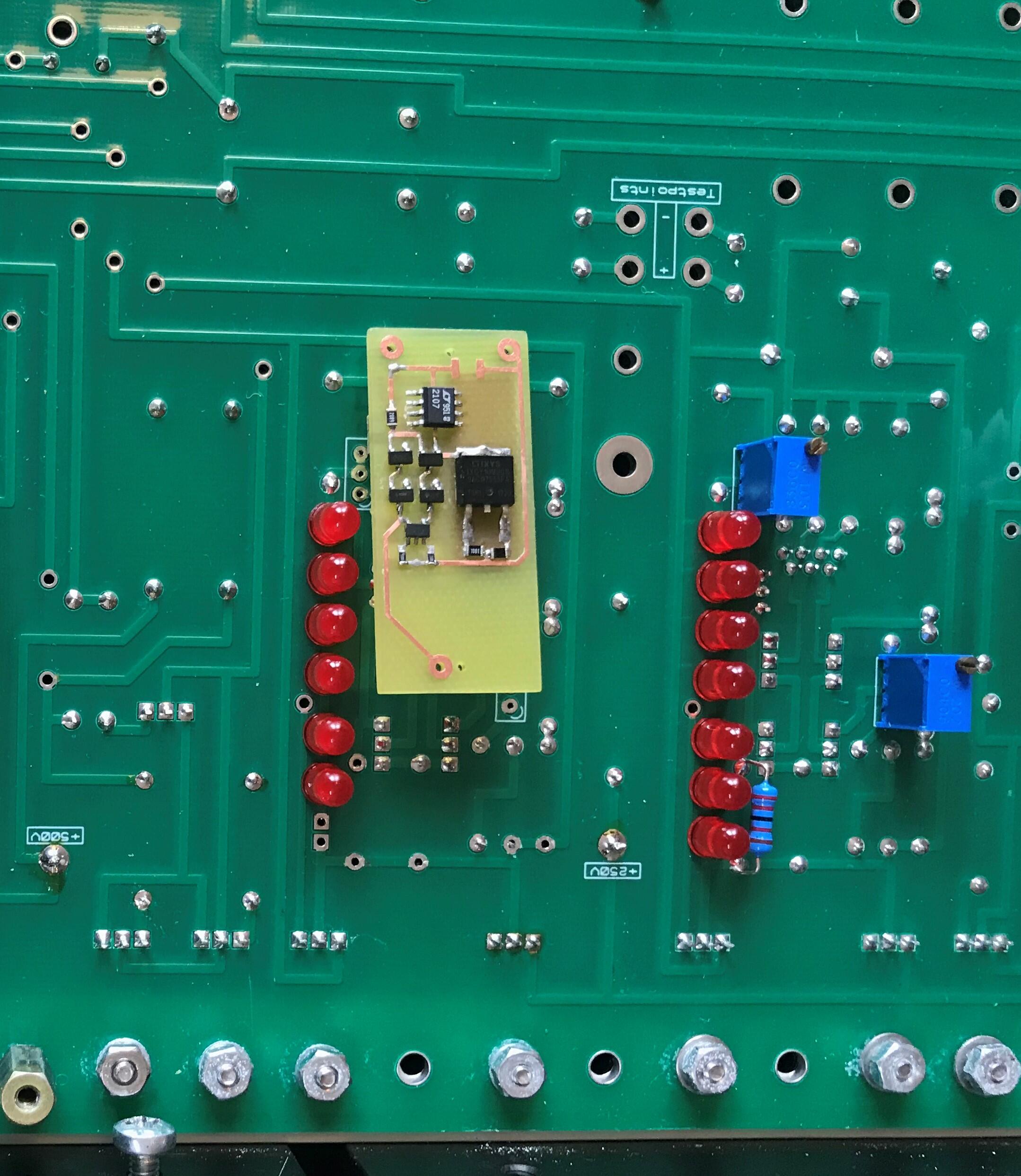
Made a new small board. All components moved to one side and a sot-223 1200V npn added to form a Darlington pair with the big npn in the battery. It’s possible to use it with Kevin’s original DIY T2 board. Remove battery components from main board and solder in the daughter board (three pins, fits right in) if you dare. Myself I’m a bit shaky after last failure.
-
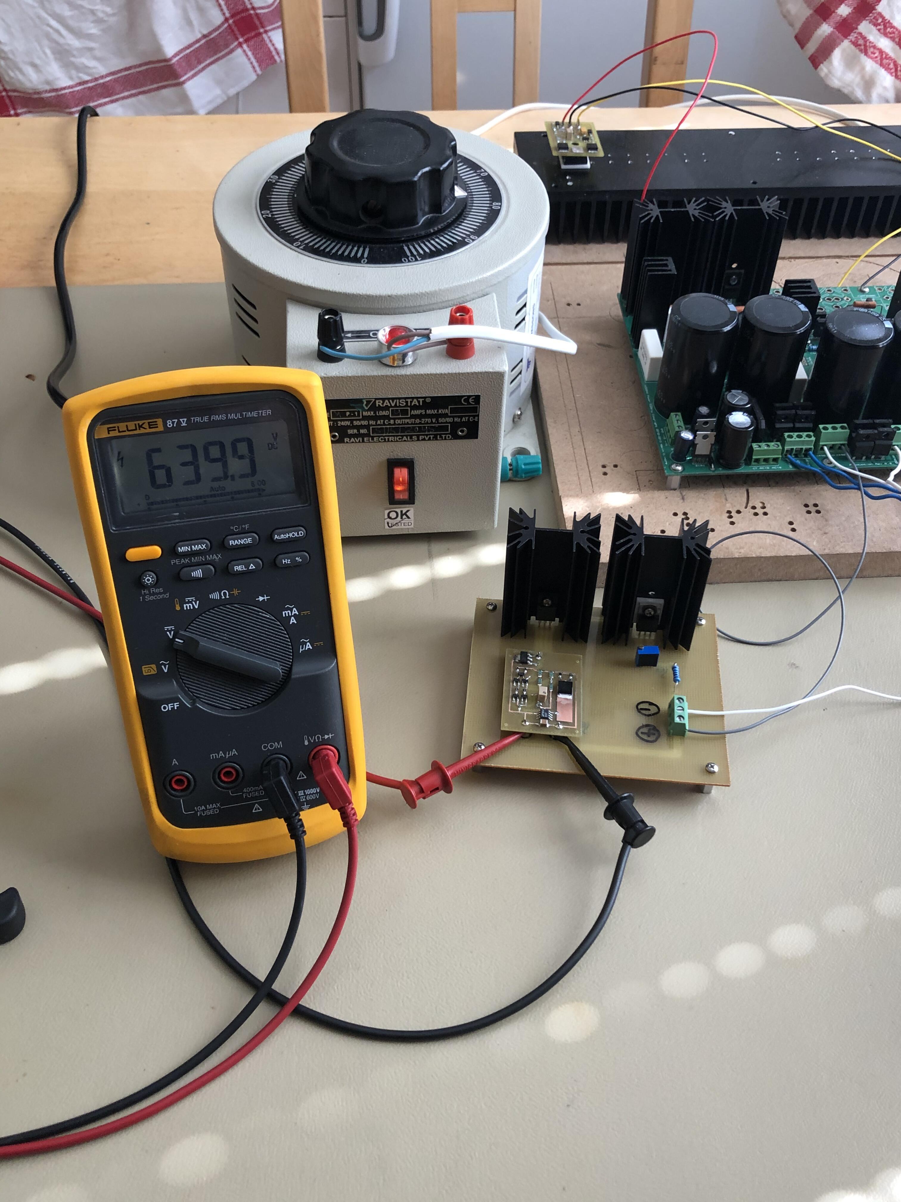
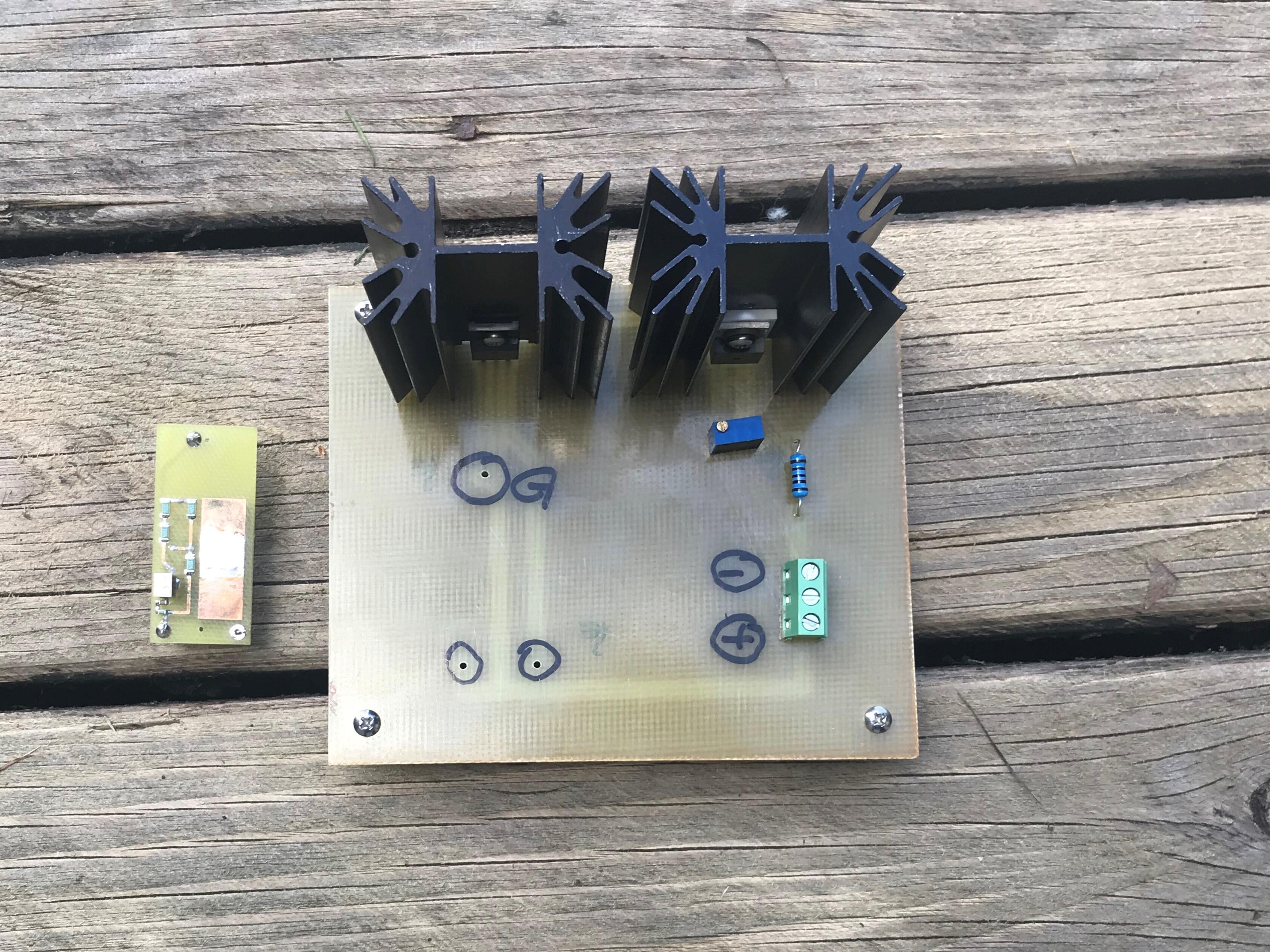
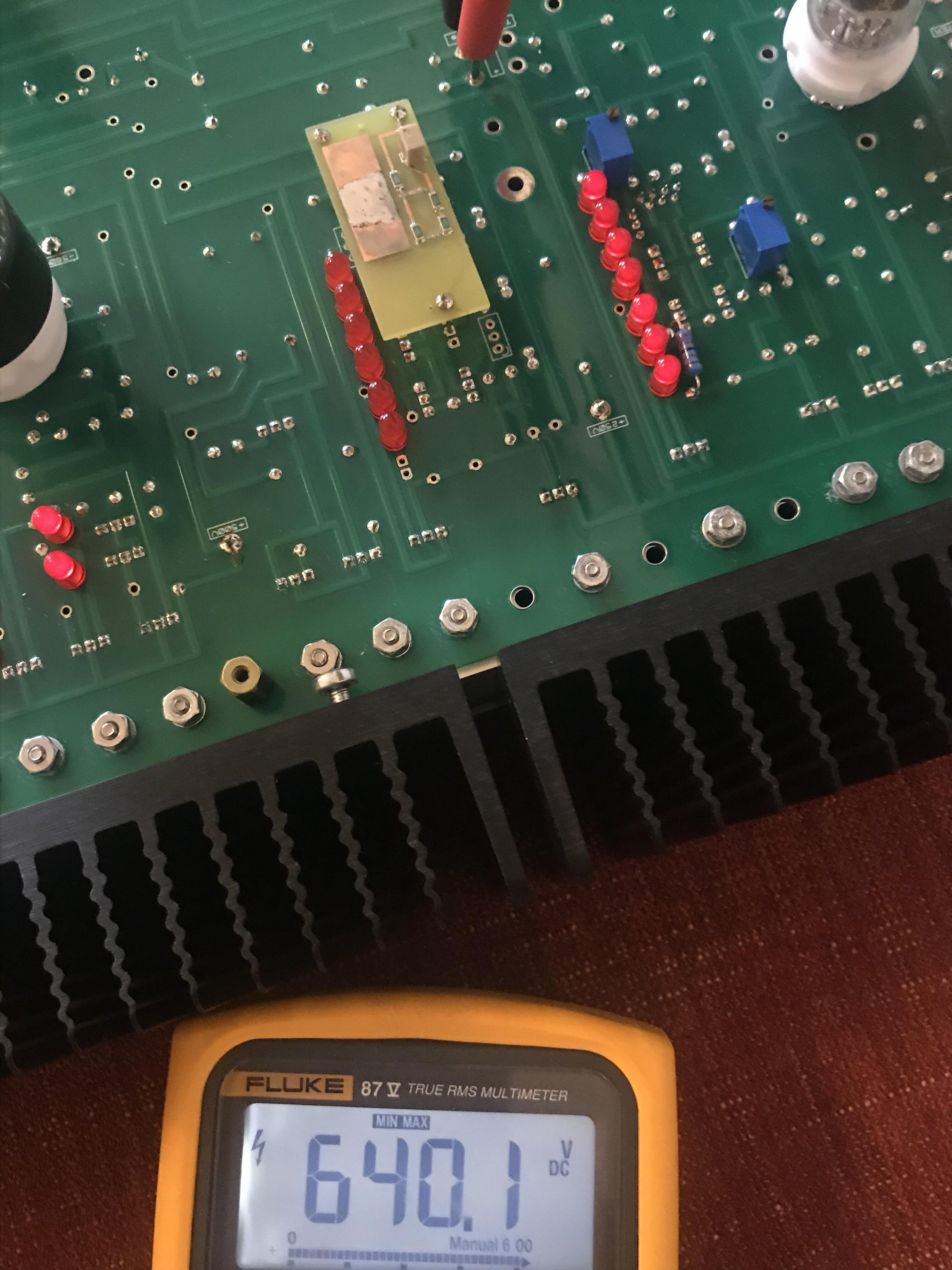
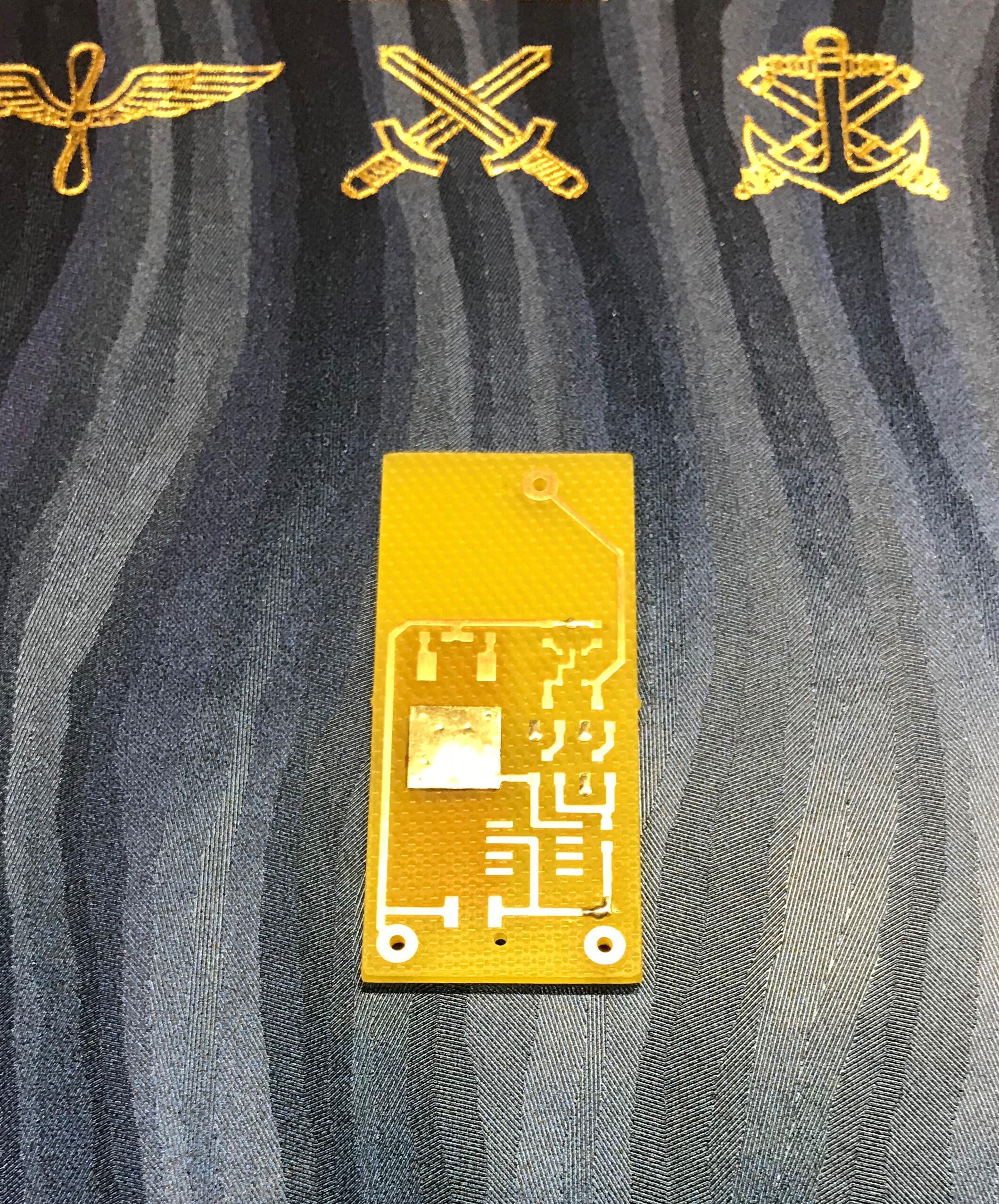
Thank you. Using a T2 amplifier as a test bench might be… not so smart. Milled this test board today. On heat sinks; 10m90s current sink to the right and high voltage npn to the left. The small board on the left is the battery that killed my T2.
-
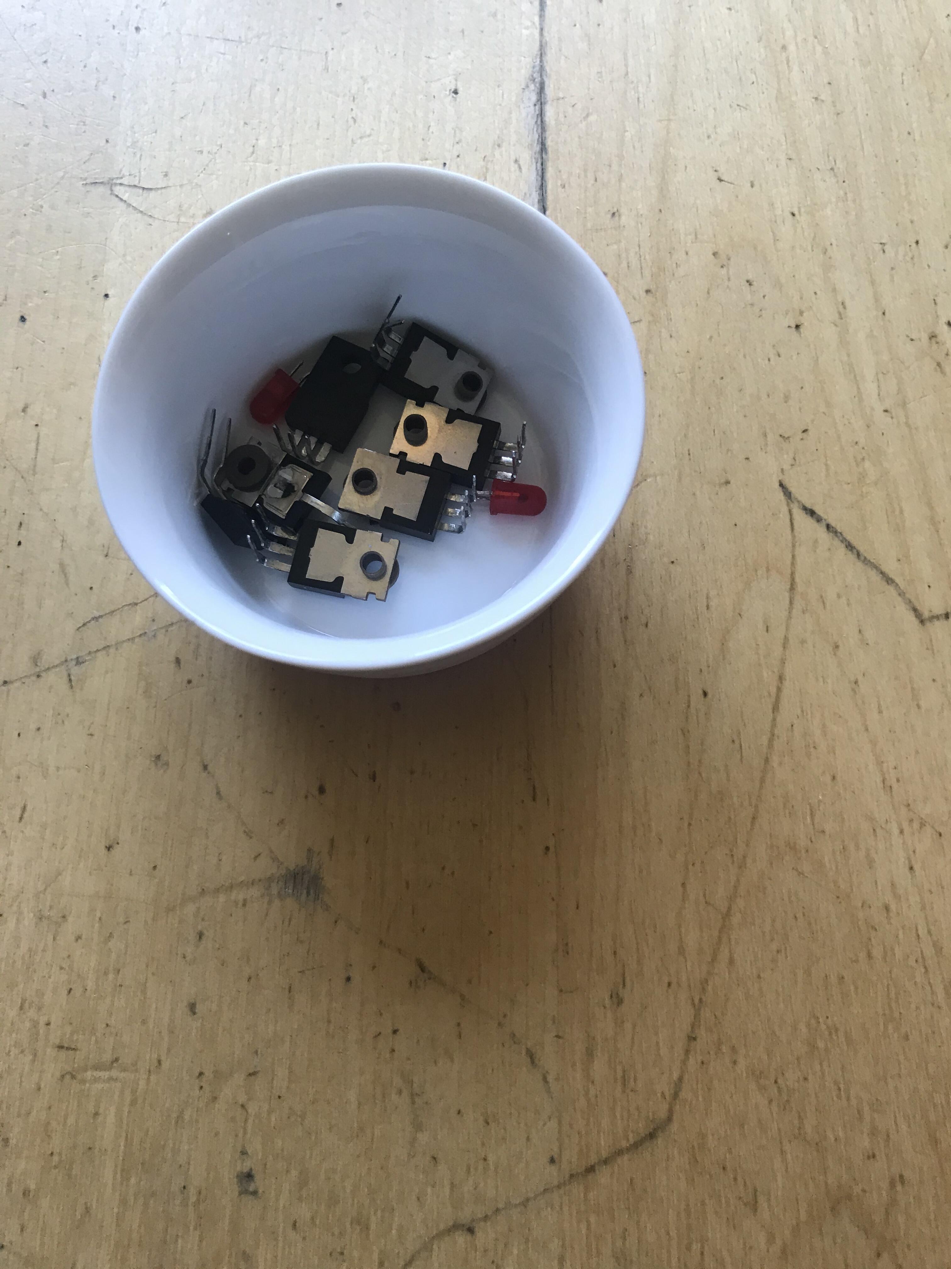
Since there is no "What Are You Destroying Today" thread I post here. Yesterday, while trying a modification to a battery on the T2 that was meant not to be modified in any way I had a "gun shot" when high voltages were applied. I had to replaced three mosfets, two zeners, and one power resistor in PSU. Amplifier needed four c3675, three k216, only one j79 and two leds. Now I’m happy again. Some broken parts in a small cup. RIP.
-
May I ask - what software did you use to create files for CNC machine?
-
Deleted!
-
Thanks for LTspice files. When I open “kgsshv_carbon.asc” I get message “Couldn't find symbol(s): power_nmos_heat”
-
Happy Birthday, Wachara!!!
-
Now when Kerry regulators and psu board are on its way I and maybe a few other builders wonder what transformers might be appropriate. James, @jamesmking, what transformers did you acquired for your mini T2?
-
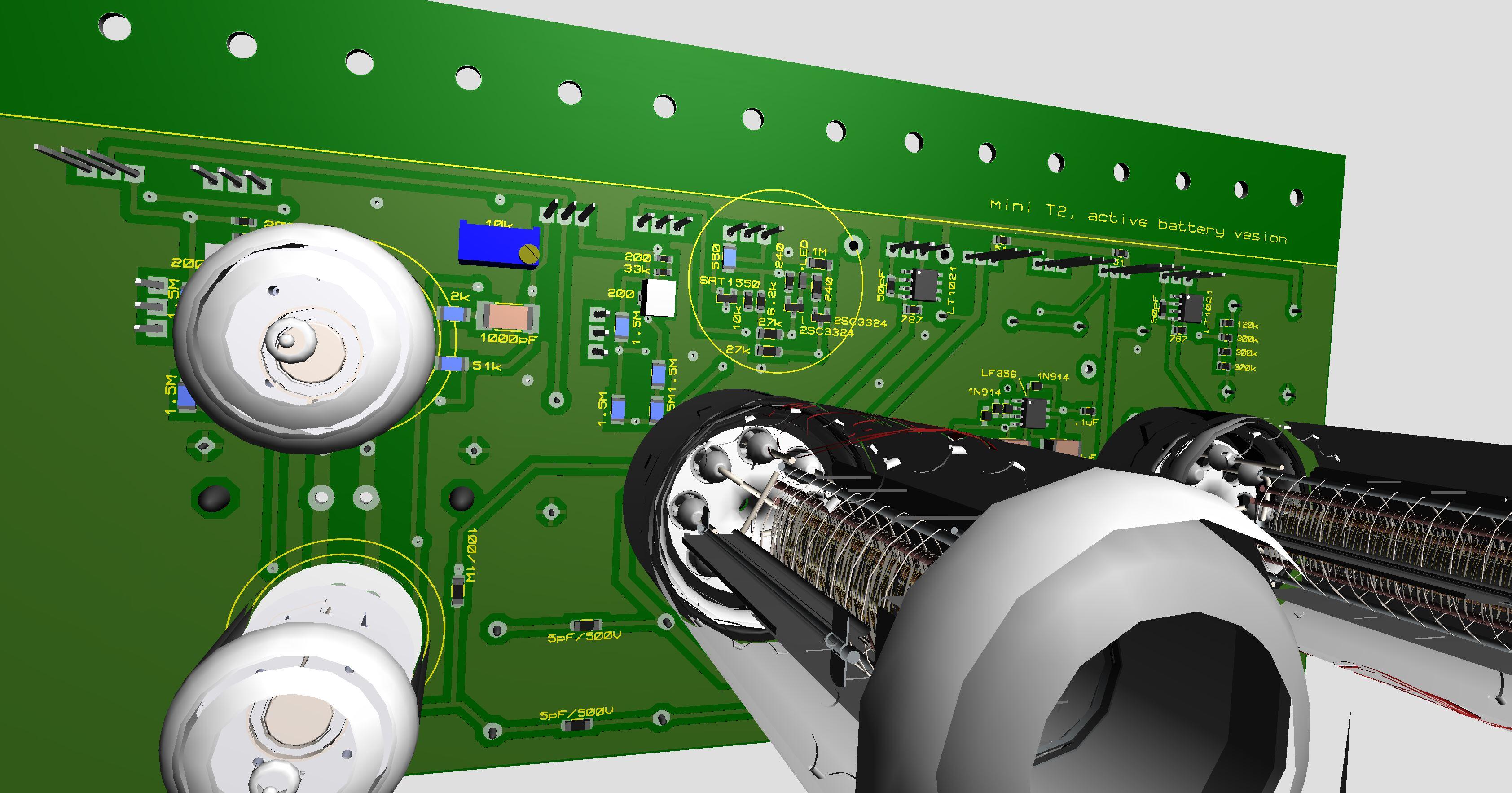
A version of mini T2 with active batteries. Battery has lt1021 voltage reference and a current sink ensures it works properly. Under batteries and input tubes is a small circuit (in the yellow circle) – same circuit in DIY T2 has five 2sc3675. Only exists in fantasy.
-
Some progress. Replaces the original battery in my DIY T2, which was supposed not to be modified in any way… Schematic:
-
Try those modern components and reduce high voltages to +/-400V (I’ve tried all except KSC1008 and J112). Old Modern 2SA1468 KSA1156 2SK216 KSC2690A 2SJ79 KSA1220A 2SC3381 KSC1008 2SK246 J112 2SK3675 FJPF2145 Mouser wants $51,51.
-
Looks very nice. I like the negative regulator. Milled today. Board has 13 vias and I think I've found a good way to make it in our kitchen (turnaround time is an hour or so (more likely a couple of hours)). STN9360 is too big for this board. STR2550 is much smaller and there is room for four of them plus LT1021, 10M90S, HN4C51J and a few other components on the other side.
-
Now printed stencil 0.2 mm thick and I don’t think it will work, not with my printer anyway, a Prusa i3. Printer has big difficulties with small footprints as so-23 and sot-26. The others might work… maybe, not sure. Also the side towards pcb is to rough.
-

Kerry Design mini GRHV\GRLV and JoaMat mini T2 Group Buy
JoaMat replied to mwl168's topic in Do It Yourself
Money sent, thanks. -
Print this file mini T2 left top stencil.zip in 3D printer and see if it is useful as a stencil (top layer left channel). I've never ever done this stl file is created by https://solder-stencil.me/.
-
I guess most of the parts on underside will stay in place by surface tension. If they fall down don’t blame me – put blame on Newton. Anyhow, I held pcb upside-down and blow 360C at flow 5 for five minutes and 0805 resistors and HN4A51J stayed put while solder was liquid so I could move them off with a tweezer. For me the most difficult is to put the right amount paste on pads, it easily become very messy…
-
Thanks. Now I’ve done some more practice. First solder with leaded solder and then with lead free. Guess I prefer leaded as it’s faster and a bit easier. Trying different settings. 300C and air flow at 5 seems to work with small parts and leaded paste. I can do it all with one hand. 1; solder paste on pads. 2; put component with tweezer on pasted pads. 3; blow hot air till paste melts and sucks component nicely in place on pads. Only right hand is needed. One hand left for... a good cigarr…
-
OK, I'm trying and hopefully learning something, with solder paste and component in place and then hot air. What temperature and airflow did you use? Also what type of solder paste?
-
Kerry Design mini GRHV\GRLV and JoaMat mini T2 Group Buy
JoaMat replied to mwl168's topic in Do It Yourself
Michael, Add 2 mini T2 boards. Thank you, Joachim -
A few years ago I bought a Weller hot air station WTHA 1. It was my first hot air station and I thought it was a good station. It was quite expensive so it had to be good! Suddenly the display showed “Error 3” and nothing more happened. No guarantee left and I couldn’t remember from whom I bought that crap from. After some investigation I bought a Quick 861DW. Now I’ve used the Quick for a while and I’m very happy with it and it costs a third of the Weller - and ten times better. I use a Weller!! solder station for smd soldering and have no intention to change that. But when working with the Quick hot air station the last days I tried to solder components with the Quick and it did work quite well. So, first I thought this is a complicated way to solder smd parts.. … but I now I’ve changed my mind, well worth trying – Thanks for sharing this, James.