


JoaMat
High Rollers
-
Joined
-
Last visited
Everything posted by JoaMat
-
like a Gran Reserva
.thumb.jpg.1db18252271fe3a0a8766dff21576340.jpg)
-
-
Report from cuisine de joamat. One side of the balanced board works alright – able to set output current and offset is within a millivolt. The other side – output current controllable but servo doesn’t work as desired, offset, varies round plus two and a half volt. Here is an aerial picture of the output board. I’m not so happy to dive in with test pins in there… and servo parts on the bottom side. …maybe I should be satisfied with one working side out of two possible.
.thumb.jpg.f5ca396ccf917bd39bf1d364fa6cbaf3.jpg)
-
94 seconds of Mozart: Allegro in D Major, K.626b/16 " performed by Seong-Jin Cho yesterday in Salzburg. I heard the piece today, tvice, on BBC Radio 3.
-
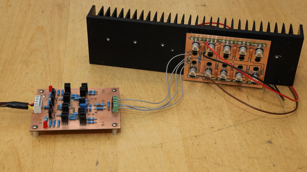
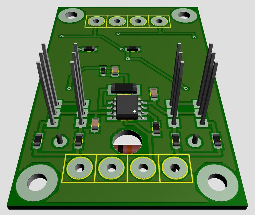
A small step towards a balanced Raal UberAmp setup. Completed a balanced smd (mostly) driver board today. Size 99mm x 35mm (3.9in x 1.4in). Two through hole unbalanced driver boards for comparison.
.thumb.jpg.60e2c138bed28d0c73a5b879bd5e653b.jpg)
-
I have a reworked board layout of t2hvandlvpsukgsshv2 to a golden reference style T2 power supply.
-
bdent.com has 83 pieces of 2sc3675. Grab them before they are gone.
-
Did some “google” and found a supplier in EU of Mogami W2534 with connectors. Advice most appreciated.
-
I’ve reduced power board voltages to +/-12 V. Two Mean Wells 12 V capable to deliver 29 A. Heat sink temperature decreased considerable – of course. My old ears think the sound is as good as with +/-24 V Next step is to make a few more boards to get a balanced set up.
-
Happy New Year to You all!
-
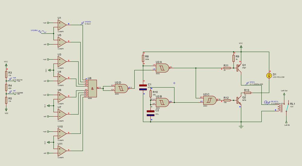
I managed to get this working in Proteus. Headphone protector. A combination of Kevin’s comparator based protector and Stax delay circuit. Delay time set by C1/R8. LED D1 is blinking when relay is disengaged and steady when engaged. The screenshot shows U1 detecting an error – relay disengaged and LED is blinking…
-
Thanks for info, Kevin. Now changed driver voltage from +/-15 V to +/-35 V and op amp to OPA445 (from OP27). So far I’m happy with the outcome.
-
Merry Christmas!
-
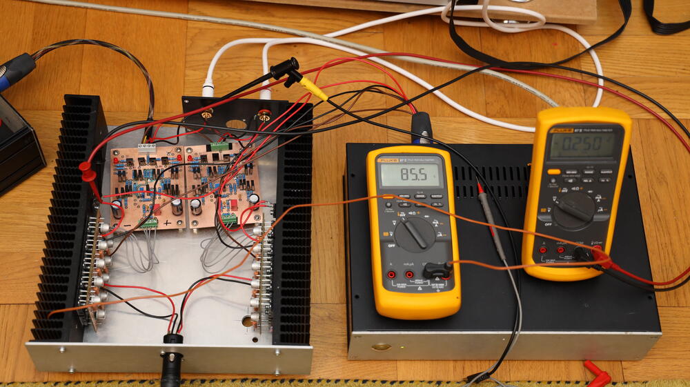
Completed a second channel of a Raal amplifier. Current through output boards are 2.5 A giving heat sink (Modushop 300 x 40 x 80 mm) temperature of 85 degree Celsius (185 dergee Fahrenheit). Driver boards powered by +/- 15V. Original it’s +/-35V. I might try the higher voltage but my idea is to use mostly smd parts in driver boards and then you probably have to reduce voltage to something like +/- 15V. There is no bass filter at the moment on the boards but Roon is taking care of that. Rear plate is to short. But that was what I had at hand – shouldn’t affect the sound?
-
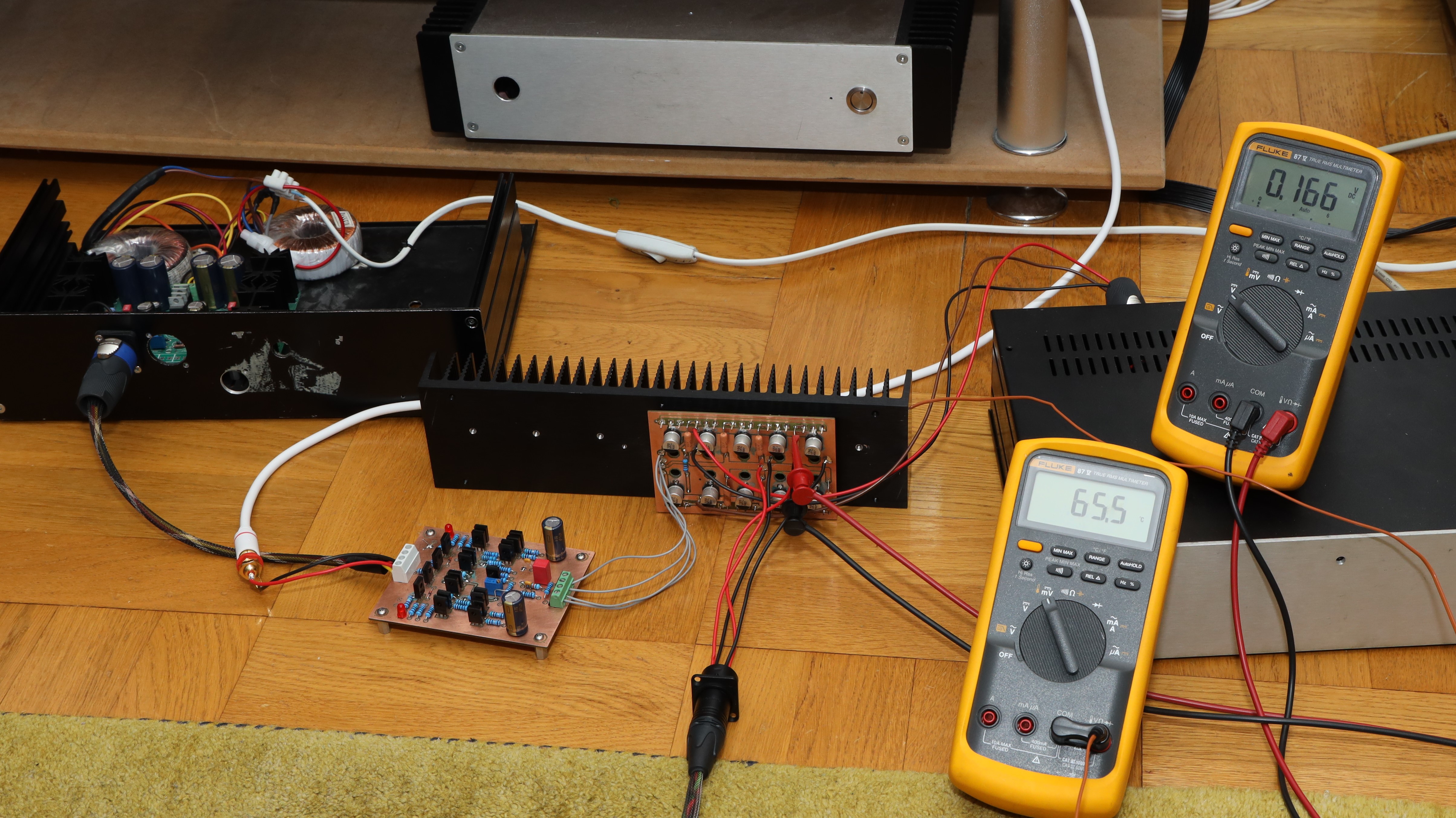
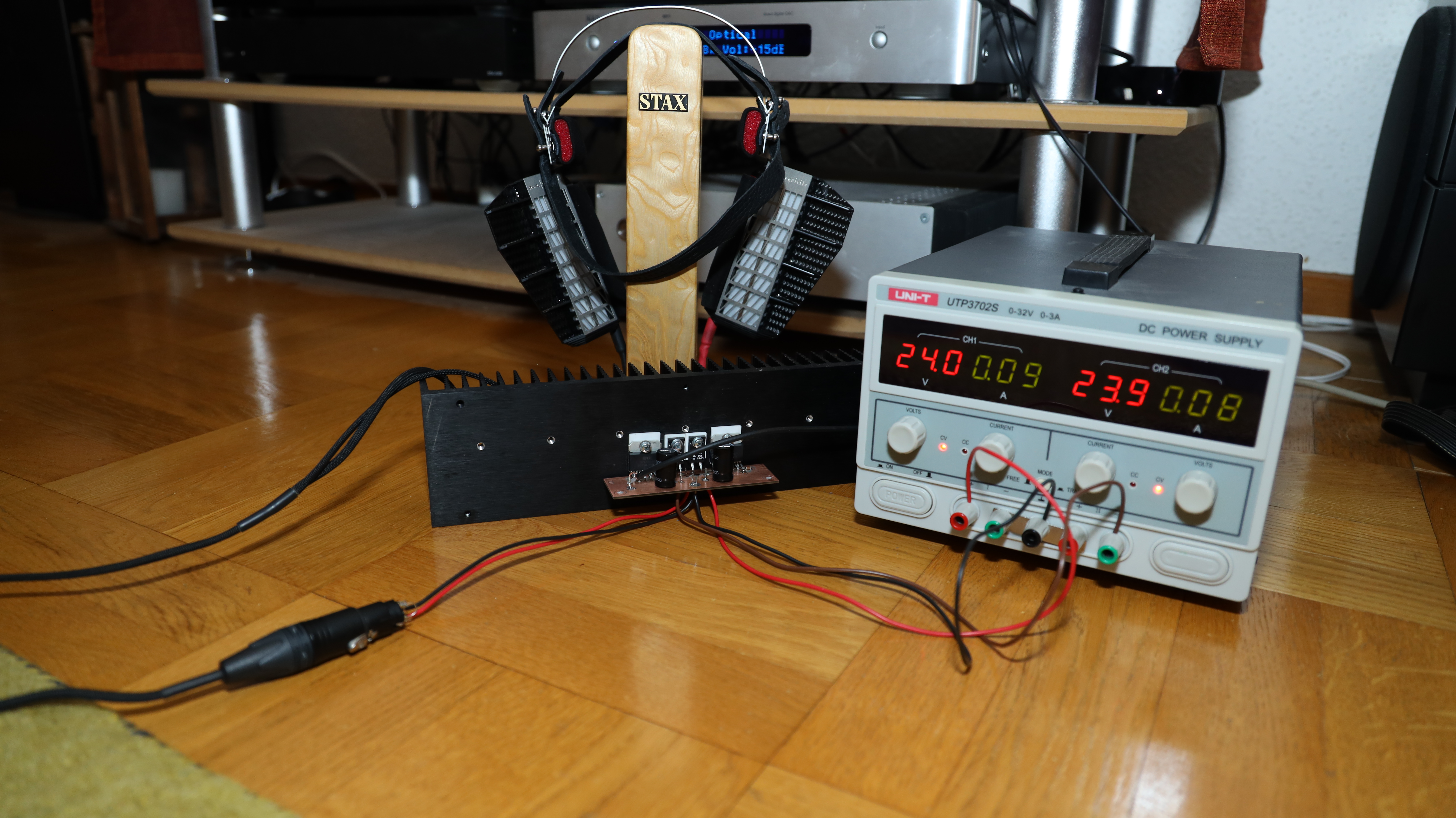
Here on ”test bench” or floor. Output board on heat sink powered by the box to the right containing two Mean Wells 2*24V/15A. Driver board is powered by AMB dual sigma set at 15V. Upper DMM shows 0.166V cross one of the 0.47 ohm power resistor. 65.5 on the other meter is temperature in Celsius, prob has a special hole in the heat sink. I’ve run this at higher current… 95 degree Celsius - not got good for wooden floor. Sound quality – interesting. Try a balanced version. Two output boards on one (bigger) heat sink…

-
So far only been connected to power supplies. Have had a couple of long nights in kitchen.
-
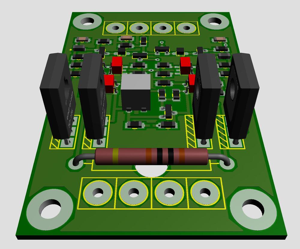
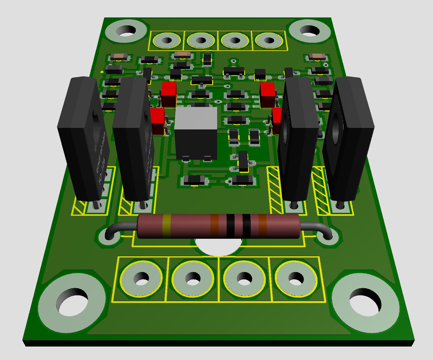
Here is an attempt to make a “smd raal uberamp driver”. I followed Kevin’s schematic. The big resistor is for feedback/gain, I guess 1.5 – 2 W is required and a few components on “solder” side. The real challenge will be the power sections. 3A x * +/-24V * 8 * balanced - might be a bit extreme for headphone amplifier…
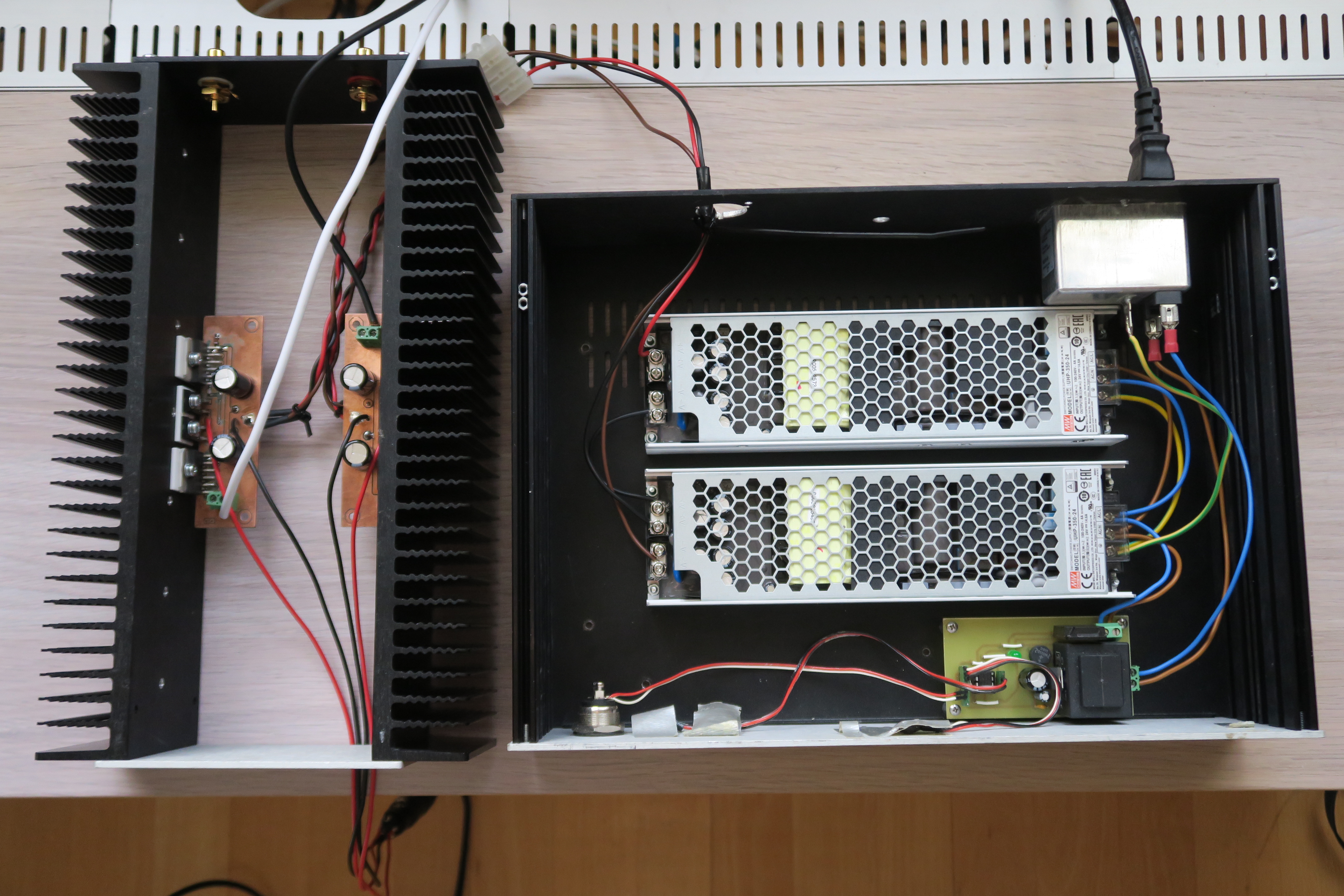
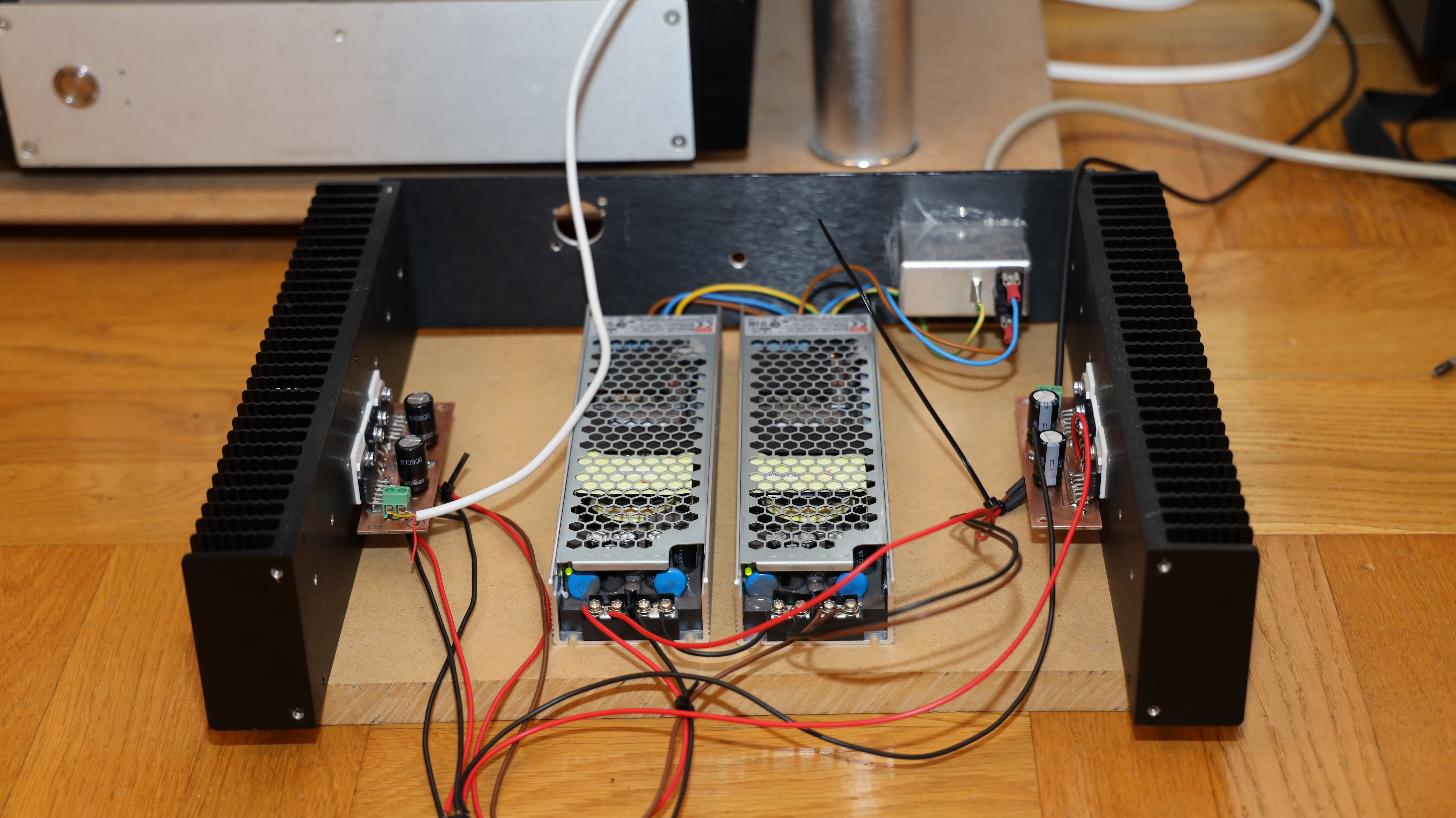
 Lately the left channel humming has increased to become even more bloody annoying. But… today I cured it (pure luck - trial and error approach). I have two umbilicals between psu and amplifier. Both carrying 580V bias and then joining at the stax connector. So, I removed left 580V bias wire in amplifier and the hum disappeared. To my ears the amplifier is now dead silent.Aerial picture of opamp driver and psu. I had some disturbing noise from the Mean Wells. After putting them their own enclosure the noise reduced considerable but there still is audible noise. With AMB’s Sigma22 supply +/-29V the amplifier was noise free. I only tried sigma22 for a few minutes since it hasn’t the current capability as the Mean Well, but it sounded OK. As for sound I find it enjoyable to listen to but I also think it has some sonically drawbacks (maybe) due to the switching mode power supplies. Bottom line is that I agree with the designer
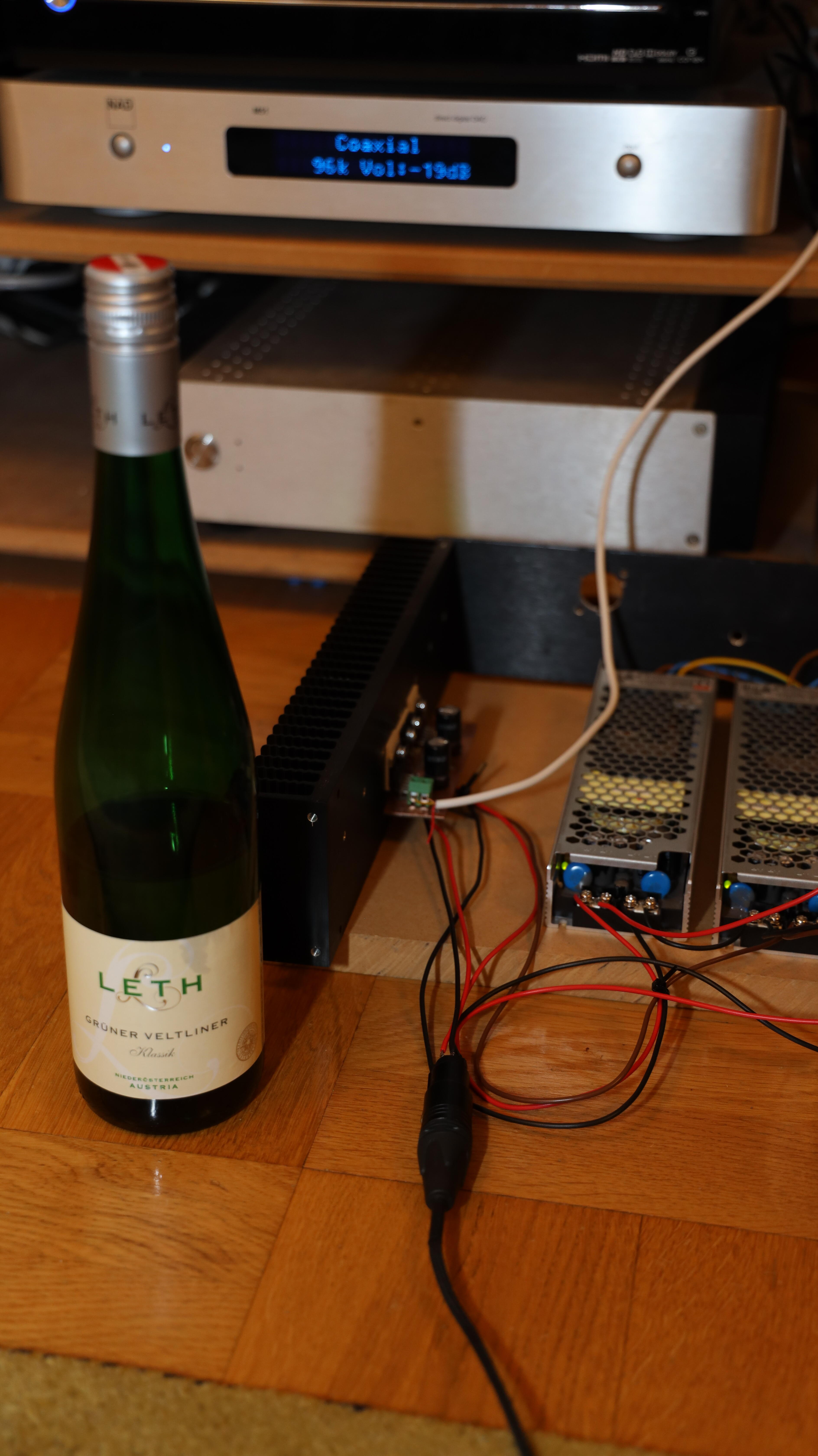
 Milled a second board today and after some struggling I eventually have a stereo opamp driver. Now I listen to this and this… Grüner Veltliner for my father-in-law... he was born in Austria.

 Here is a (my) version of Kevin’s opamp RAAL driver. Board is kitchen made. Some parts are smd but schematic is same as original. Only one channel working and it’s powered by lab power supply max 3A. Occasional when playing, not very load , leds indicating max current hit are flickering. But I've two 340W Mean Well supplies at hand. Mouser don't sell them supplies to ordinary consumers in Europe so my wife bought them for me. Lucky me.

.jpg.ce6ff2751621b8626dbe1eb226ab30d7.jpg)

.jpg.b2f42eef882914cfd1b4eacbbda52e7b.jpg)
.jpg.8b8766d7314a3aa27ffdcfe1c6ba95a9.jpg)


Important Information
By using this site, you agree to our Terms of Use.
Account
Navigation
Search
Configure browser push notifications
Chrome (Android)
- Tap the lock icon next to the address bar.
- Tap Permissions → Notifications.
- Adjust your preference.
Chrome (Desktop)
- Click the padlock icon in the address bar.
- Select Site settings.
- Find Notifications and adjust your preference.
Safari (iOS 16.4+)
- Ensure the site is installed via Add to Home Screen.
- Open Settings App → Notifications.
- Find your app name and adjust your preference.
Safari (macOS)
- Go to Safari → Preferences.
- Click the Websites tab.
- Select Notifications in the sidebar.
- Find this website and adjust your preference.
Edge (Android)
- Tap the lock icon next to the address bar.
- Tap Permissions.
- Find Notifications and adjust your preference.
Edge (Desktop)
- Click the padlock icon in the address bar.
- Click Permissions for this site.
- Find Notifications and adjust your preference.
Firefox (Android)
- Go to Settings → Site permissions.
- Tap Notifications.
- Find this site in the list and adjust your preference.
Firefox (Desktop)
- Open Firefox Settings.
- Search for Notifications.
- Find this site in the list and adjust your preference.