spritzer
-
Posts
14,685 -
Joined
-
Last visited
-
Days Won
29
Content Type
Profiles
Forums
Events
Everything posted by spritzer
-
I've been spending some time with them and yeah, that overblown mid-bass is starting to annoy me a little bit. It works with some material but can be too much of a good thing on others. It comes at the expense of actual bass depth so... not really a trade I'm interested in. Still as offensive traits go for recent Stax sets... this is pretty fucking mild and I do enjoy them quite a bit. Not replacing my 207's though... So I had make a comparison for fun. I had probably the last ever B-stock Koss ESP/9X5's sitting in a box here so why not compare them against the Stax. Similar price category but the Koss build quality is nowhere near what Stax are doing. So the Koss needed some mods, gone is the cable and they now sport the setup from a King Sound KS-H4 (so removable cable as well) and those leather earpads you can get on Aliexpress. All of the stock damping material, which was minimized on these anyway, as well. Fits like a glove and it's fun to compare these two, as aside from the HE60, these are some of the lightest and easiest headphones to plop on the head and enjoy. I've always liked the Koss as it always stood toe to toe against the Lambdas and this time it is no exception. It is more neutral and laid back, a bit more relaxed than the X1 but with better bass response. Larger drivers so it has more presence to it, more space around voices etc. Speaking of the Koss though, I wanted to sit down a try the Massdrop setup directly out of the box and holy hell... what were they thinking with those earpads. I plugged them into my test setup and on the first song, "ehh where is the all the sub-bass?" Yeah, this didn't help with the BS that electrostatics lack bass...

-
So true!!!
-
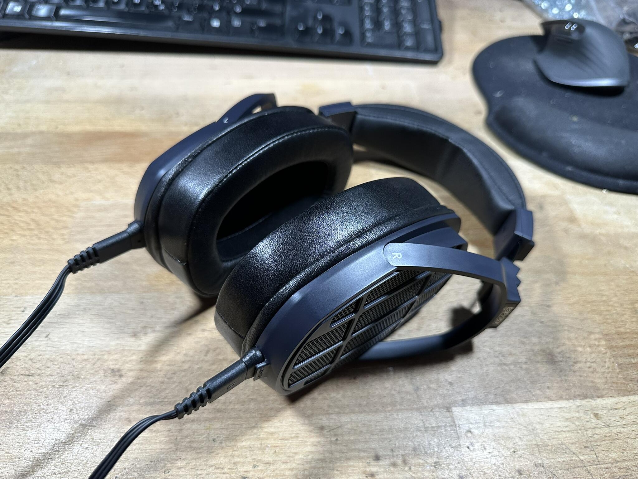
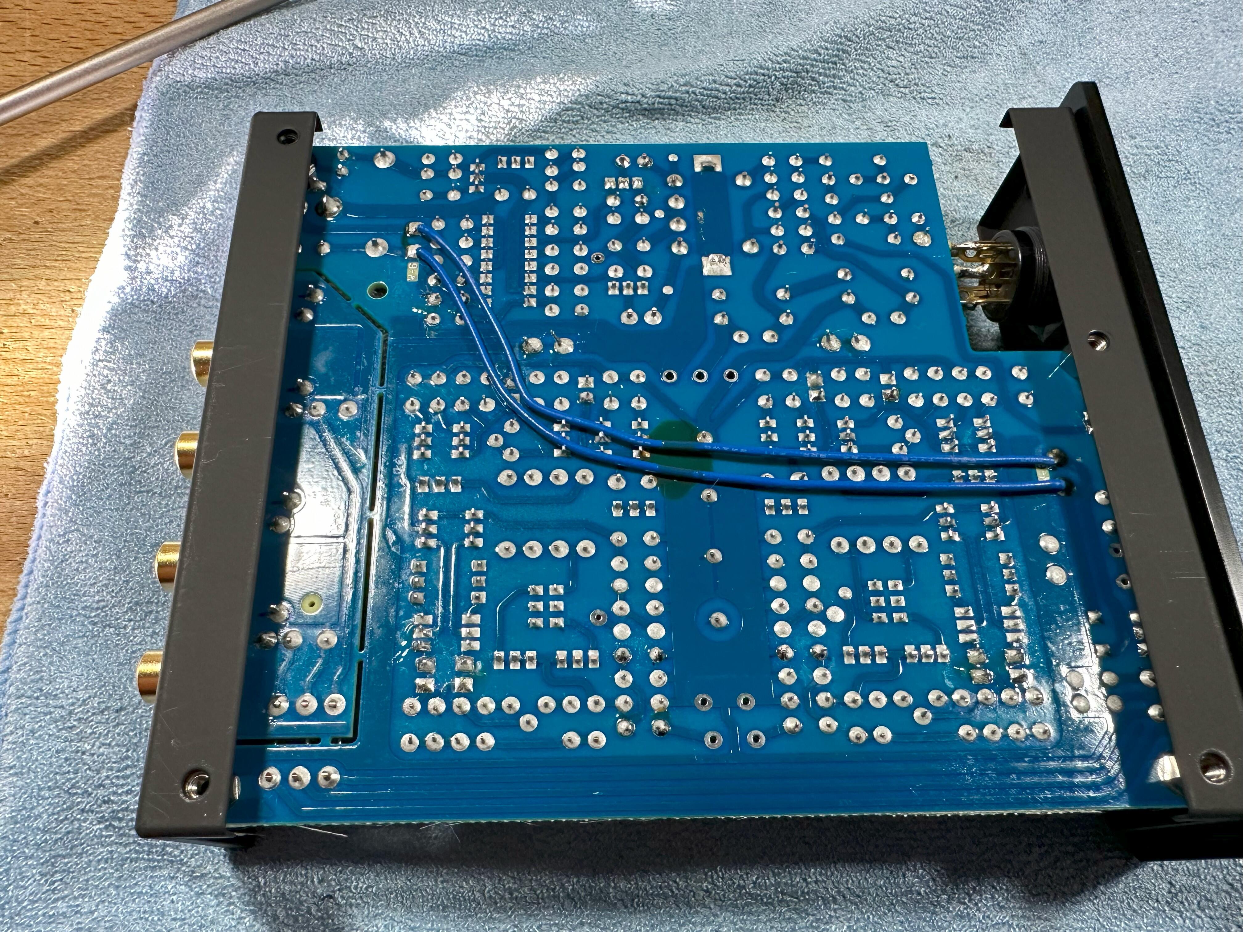
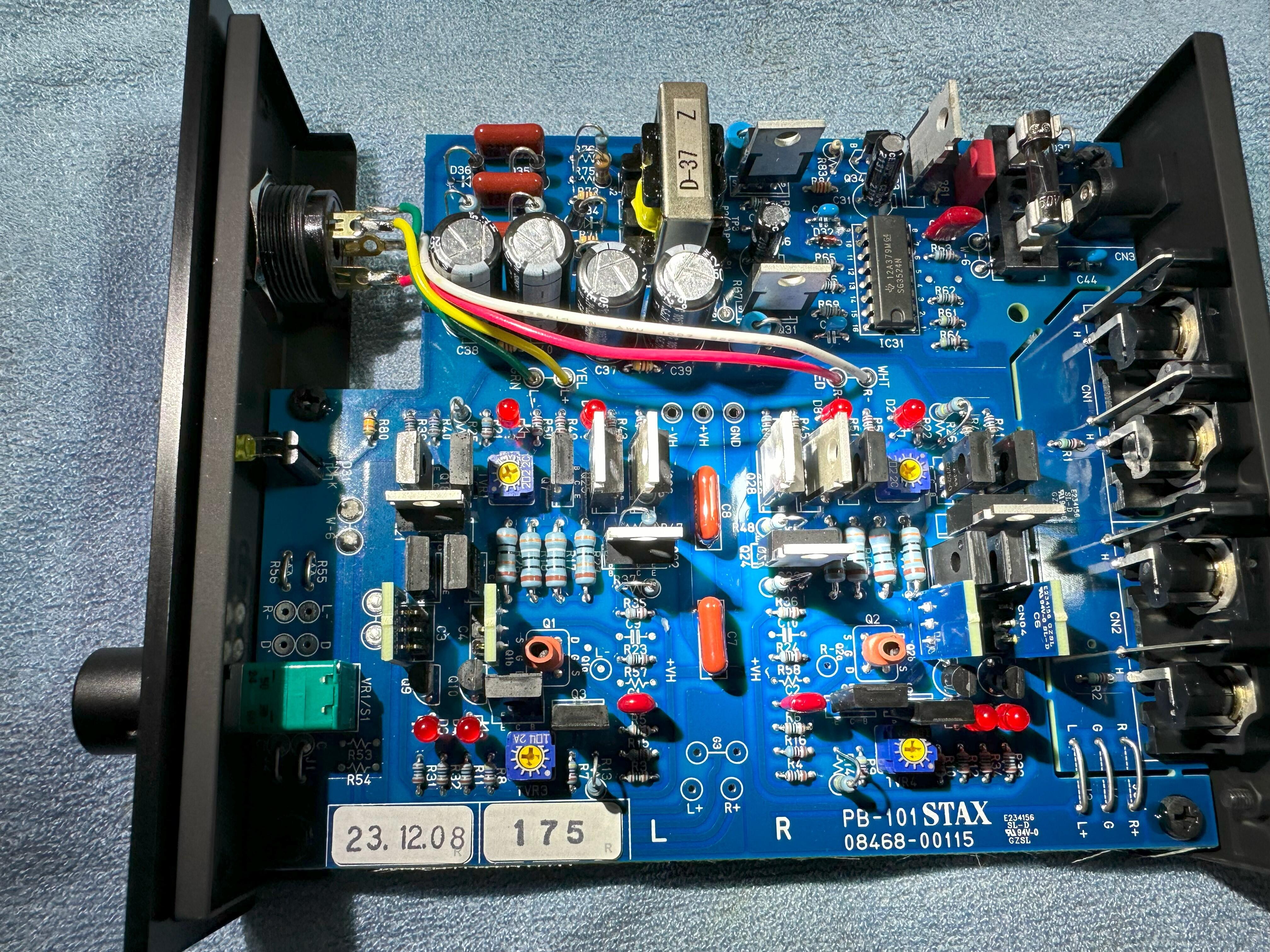
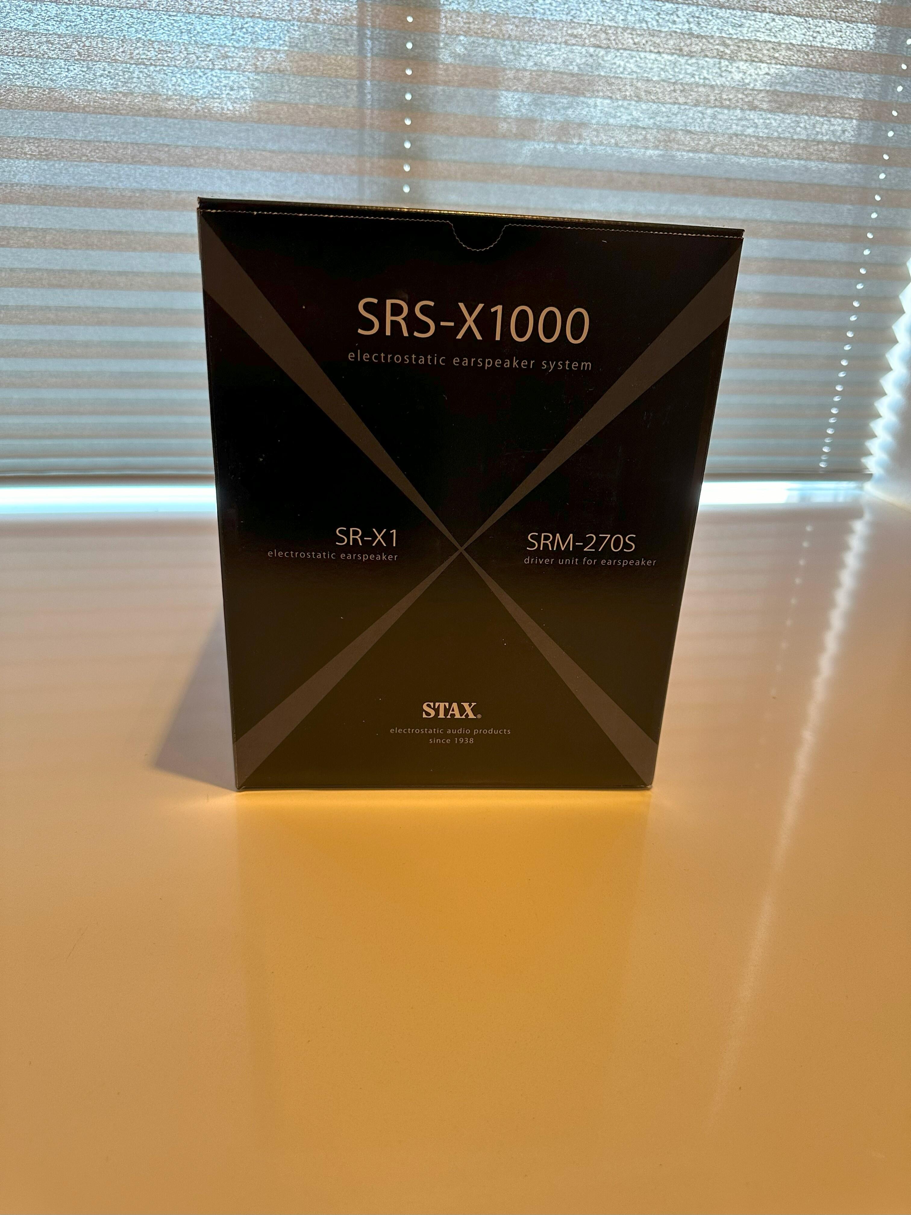
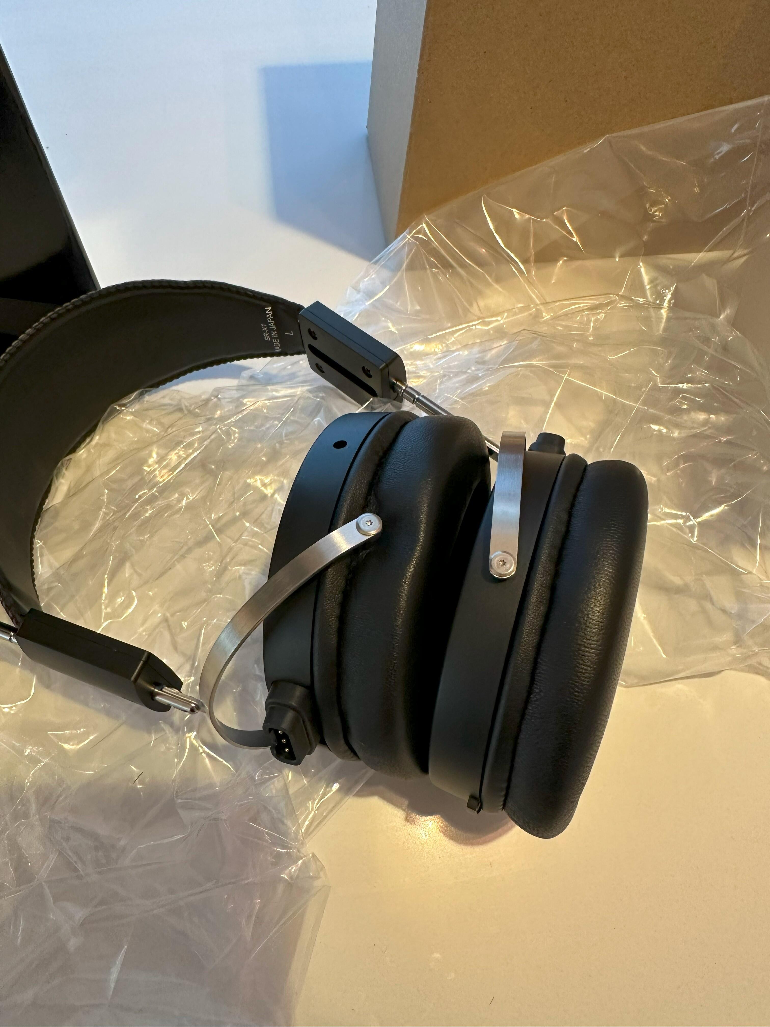
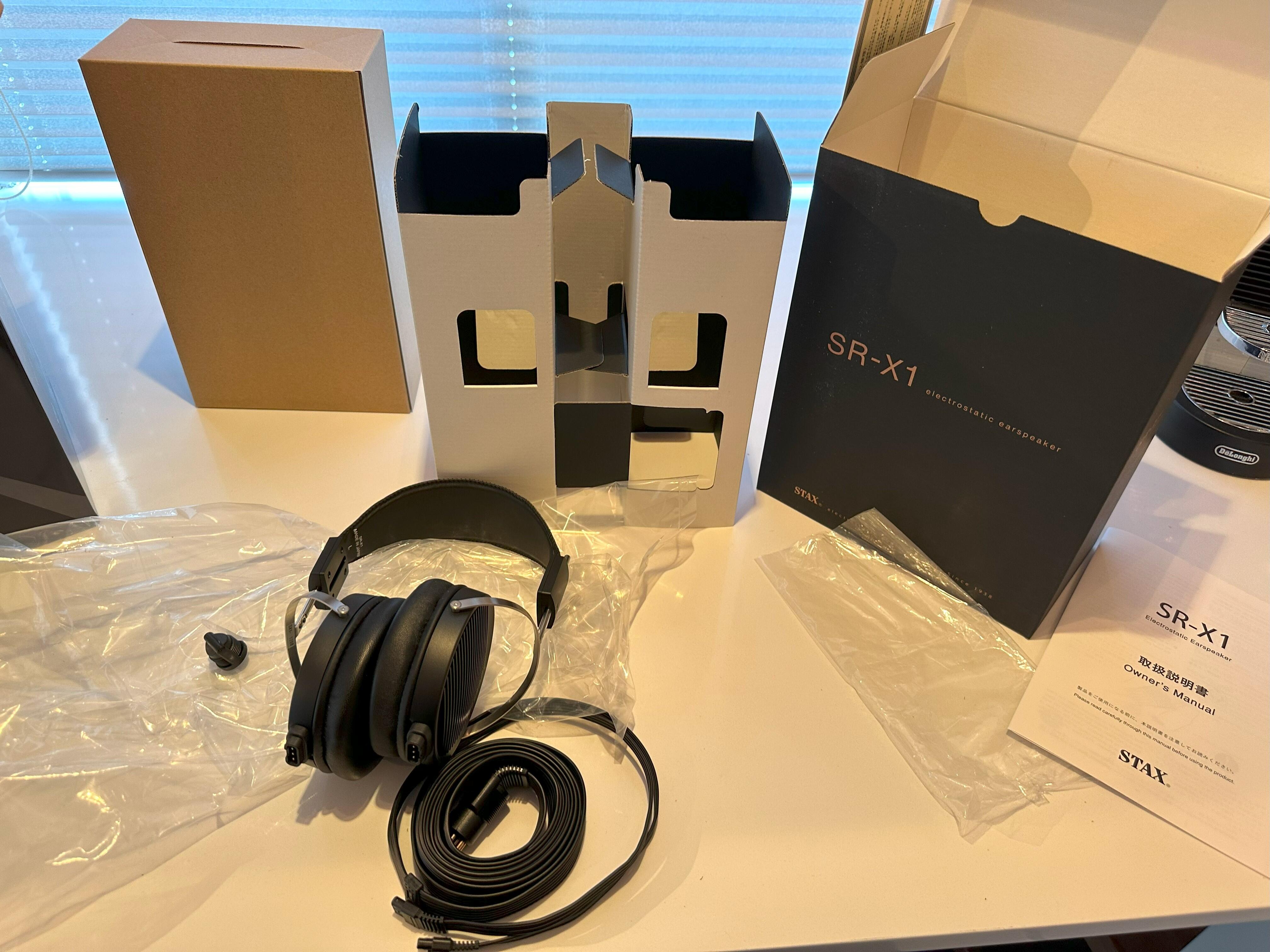
Well the SRS-X1000 just showed up unexpectedly and with all of my cameras out of juice the phone had to do. It really doesn't like the halogen lights in the kitchen... First off, this made me laugh out loud... here is how they came out of the box: Now for anybody familiar with the vintage SR-1/2/3/5 and SR-X series... this is usually how they arrived too with one or both earcups loose from the headband. Packaging is also very reminiscent of the SR-X boxes: I must say though that I fucking despise these new Stax boxes from a graphics design point of view. It looks like any cheap, tacky crap out of China... the older ones were unique and had their own thing going on but this just fucking blows. Now for the headphones it was a quick trip into the office for a listen so no more pics. Usual rig of Denarips Terminator and Carbon CC. They do feel nice in the hand though, very light and the cable actually has copper colored lines/dashes on it, not gold ones as they often looked from the pics. Gone is the blue cable... why they made that I have no idea. The headband has a lot of extension to it so even melon heads can use these. There is no padding on the headband at all but the material is firm here, not loose like on the original SR-X units. Earpads are nice and snug and seem to be nice quality, leagues ahead of the garbage on the L300/L500's. Now for sound... these sound pretty good which is a fun thing to say about a Stax set for a change. They are nice and neutral, not much forward slant here but they are quite extended on top. The bottom end is a bit lacking (smaller drivers and all that) but it is very mid-bass happy so quite fun to listen to. Midrange is a tiny bit closed in at times and the soundstage is quite closed in but it doesn't really bother me. Just that odd moment where something sounds a tad bit off but yeah... these are so much better than the L300... it's not even fucking funny. Might even be able to finally retire my aging fleet of SR-207 test headphones good... we'll see. I'll update more in the coming days but after an hour, yeah get a set. Now for the amp, first thing you notice is that it's a good inch deeper than the 252S and all of the other desktop Stax amps before it. I haven't done any circuit analysis yet but this is clearly just a version of the last 252S circuit and yup... it's still all through hole in 2024. Utterly bizarre... The extra length in the chassis is just there for the fuse and a breakout board for the RCA's. There are clearly spots on the PCB for - inputs so they might make a balanced version of it at some point? Been there, done that and while fun... it adds very little to the performance. Input Jfets are K81's so 2SK2881's and those riser boards seem to be PCB capacitors. I need to take a look at them in more detail but yeah, quite odd as they are numbered from 1 and up to 4.
-
I dropped them a line to see if I can order a pair of the headphones. Also... it was never going to be just the 007A they would cut. I'm guessing any replacement will be double the price with worse performance.
-
I've been told by more than one source that they put those "mistakes" in on purpose, same as they always labeled the balance pot "offset" and vice versa.
-
There has been this push to make the drivers more open when it can work against the overall design. Perhaps it is just fashion/trend or the designers don't understand the air-damping and now to apply it. With Stax looking to the past so much... I feel that they just don't know. I've often used Quad as an example of what happens when the main designer retires and those who come after him... have no fucking clue what they are doing. The ESL2912 is a ESL63 with all of the same issues but extra panels tacked on and higher bias, which makes them fail even more. The panels still de-laminate as they did in 1982, how hard is it to use better materials now.
-
For me, Stax simply lack focus and I'm not sure how much that is due to the new higher ups or Edifer. I certainly don't agree with the design decisions of the 009, X9000, Lx00 lineup and some just don't make any sense. They are clearly pushing boundaries in some ways with more advanced drivers but major steps backwards with basic stuff like earpad quality. It's not ok that earpads for the L500Mk2 last for a couple of years before they fall apart. Some of the products were just arguably crap, the D50 was so bad it was never sold in Japan. The D10Mk1 was utter trash and I just got a D10Mk2... it's improved in some ways but it still sounds terrible. The SRM-400S is a "what the fuck were they thinking" product and on the whole, they just took the original circuits and doubled the price.
-
Release date for the SR-X1 is set at May 9th: https://stax.co.jp/product/srs-x1000/ I've already placed a preorder.
-
Ehhhhhh fuck that guy... Anybody who sells part of a bank to his own father, needs to be taken out back and shot. Icelandic politics are such a cluster fuck right now, we have a major problem of attracting only idiots to power and it is really biting us in the ass now. Then we have the upcoming presidential elections with just one round of voting and 30 people running. It's also held in the middle of summer, 50% turnout would be high so our next president could have 4% of actual support behind him. Yeah no provision to have the two top people duke it out in a second round. Very democratic... On top of that, alleged child molesters and other trash in the running but they are from the artsy elite so nobody does anything. It's a shitshow...
-
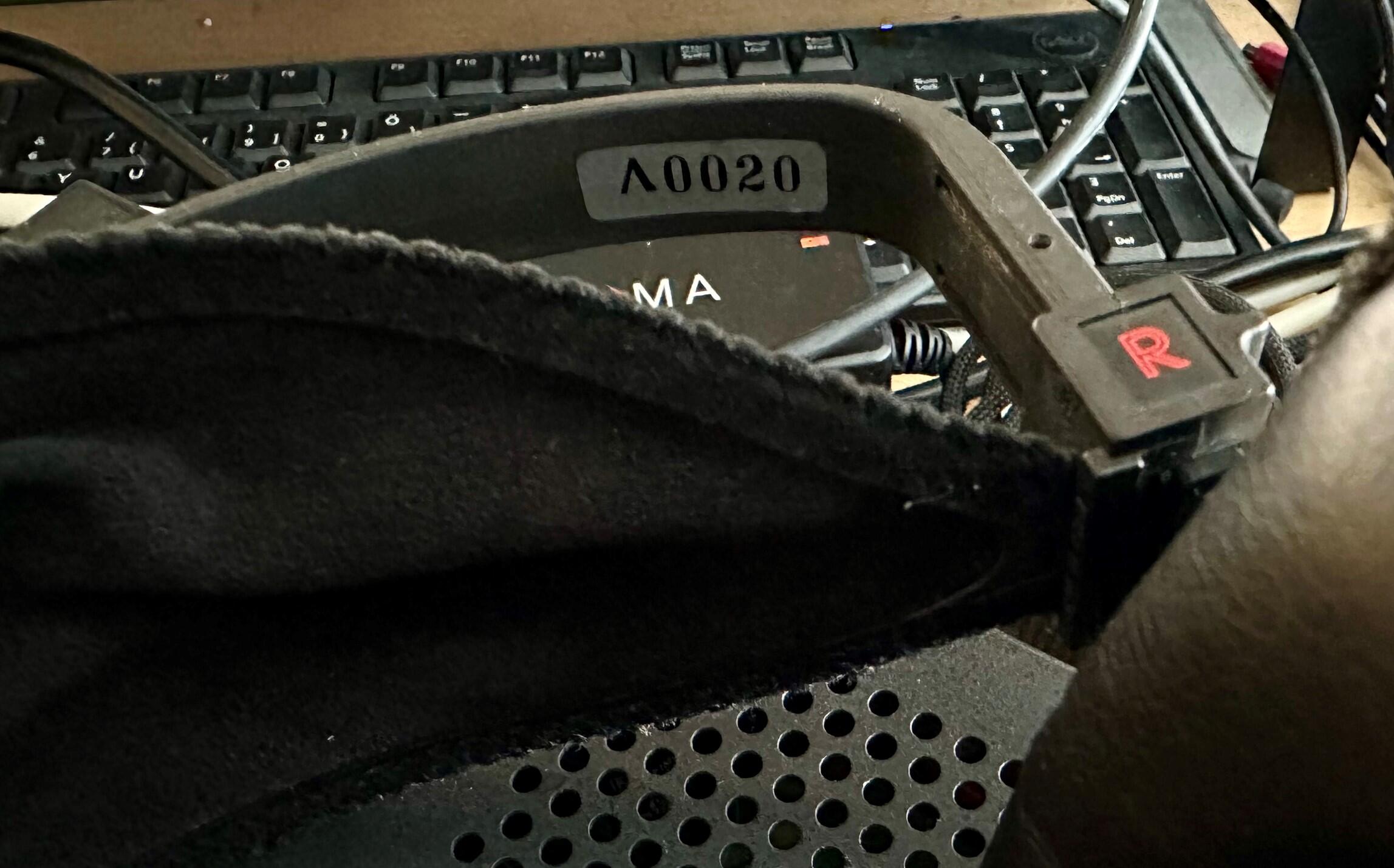
This is funny, I just bought some SRD-7's to use as donors for my own boxes. A SR-Lambda was included with one of those energizers and just look at that serial number... Aside from the foam in the earcups being crusty and the earpads having been replaced at some point, they play perfectly for a 45 year old set.
-
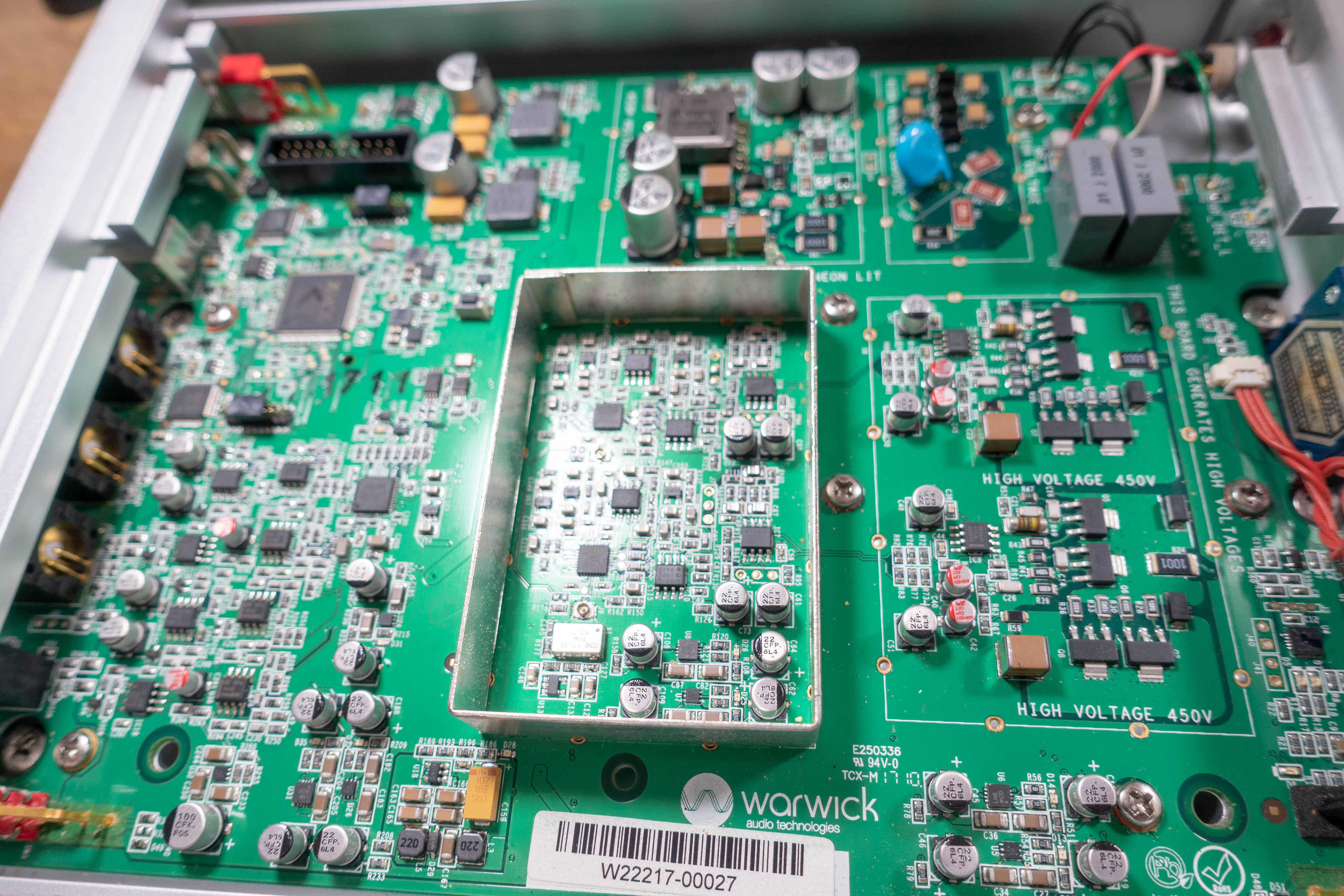
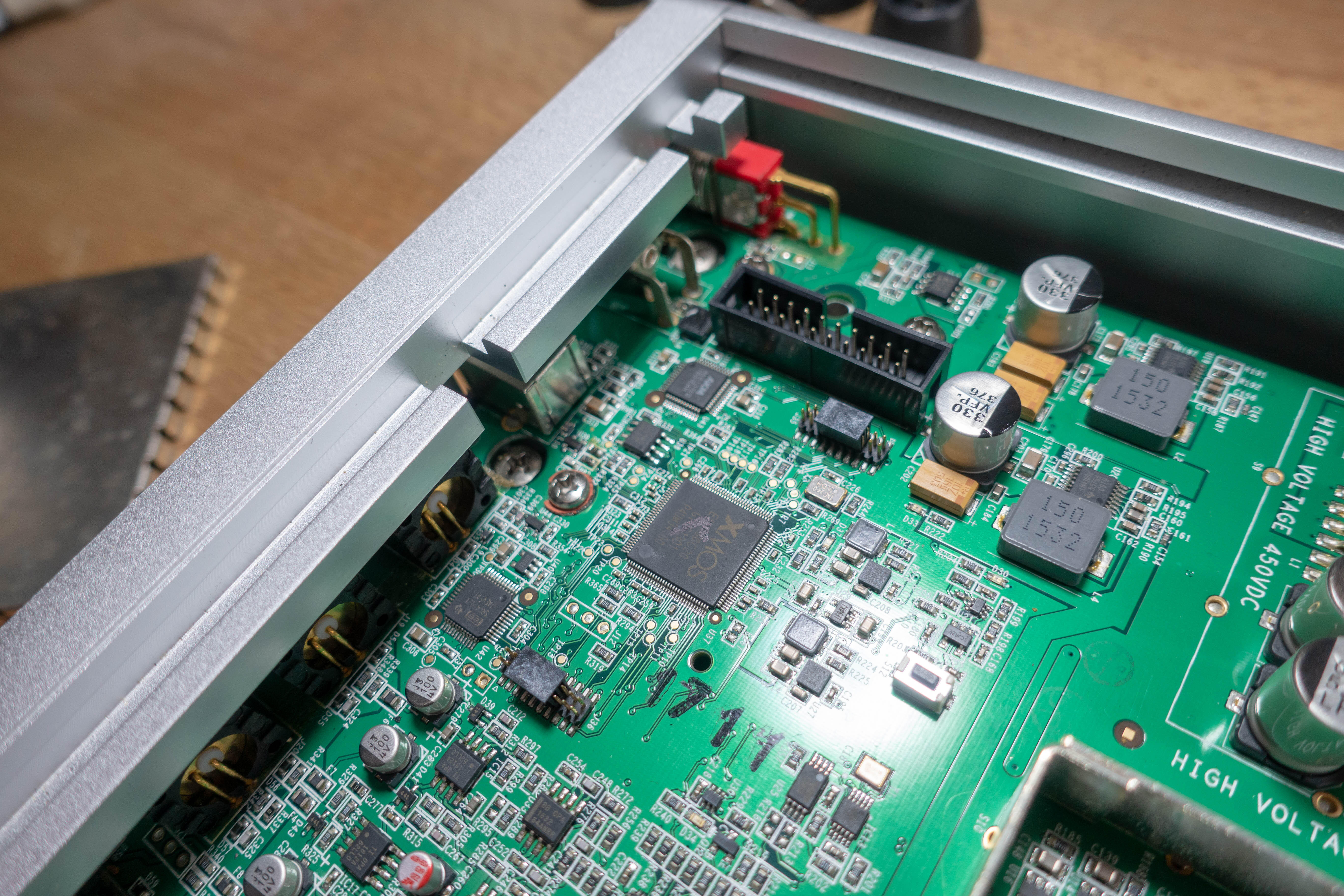
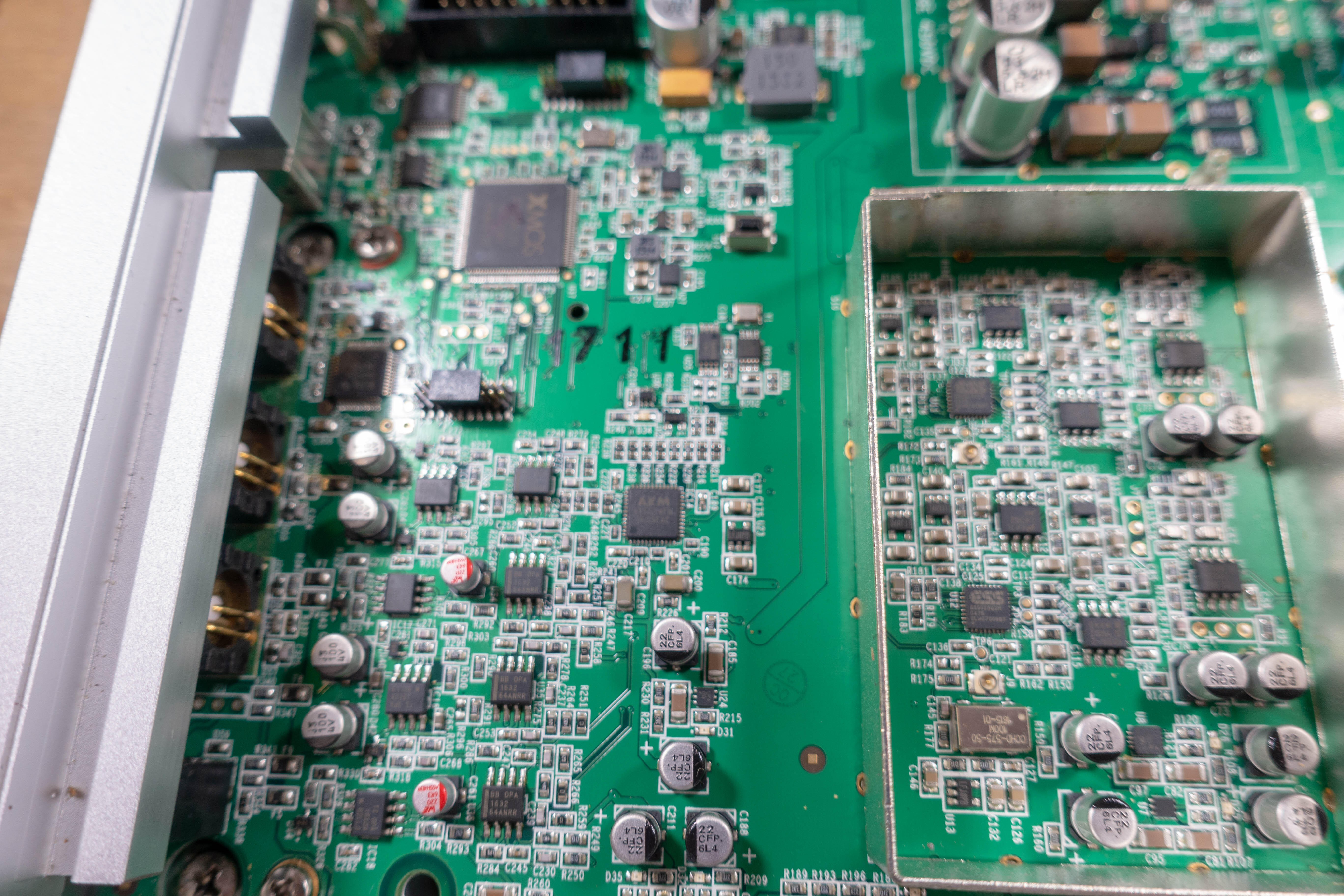
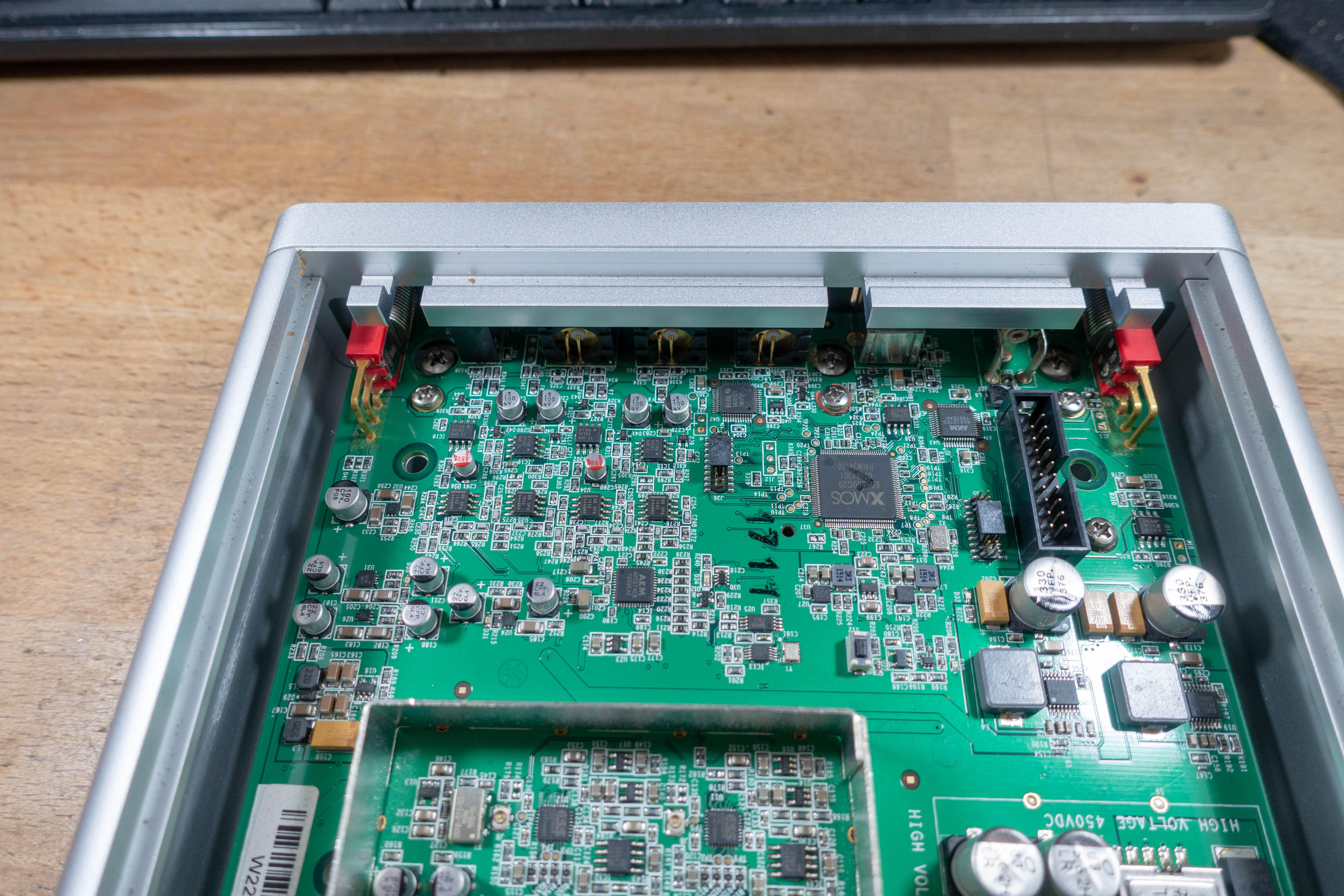
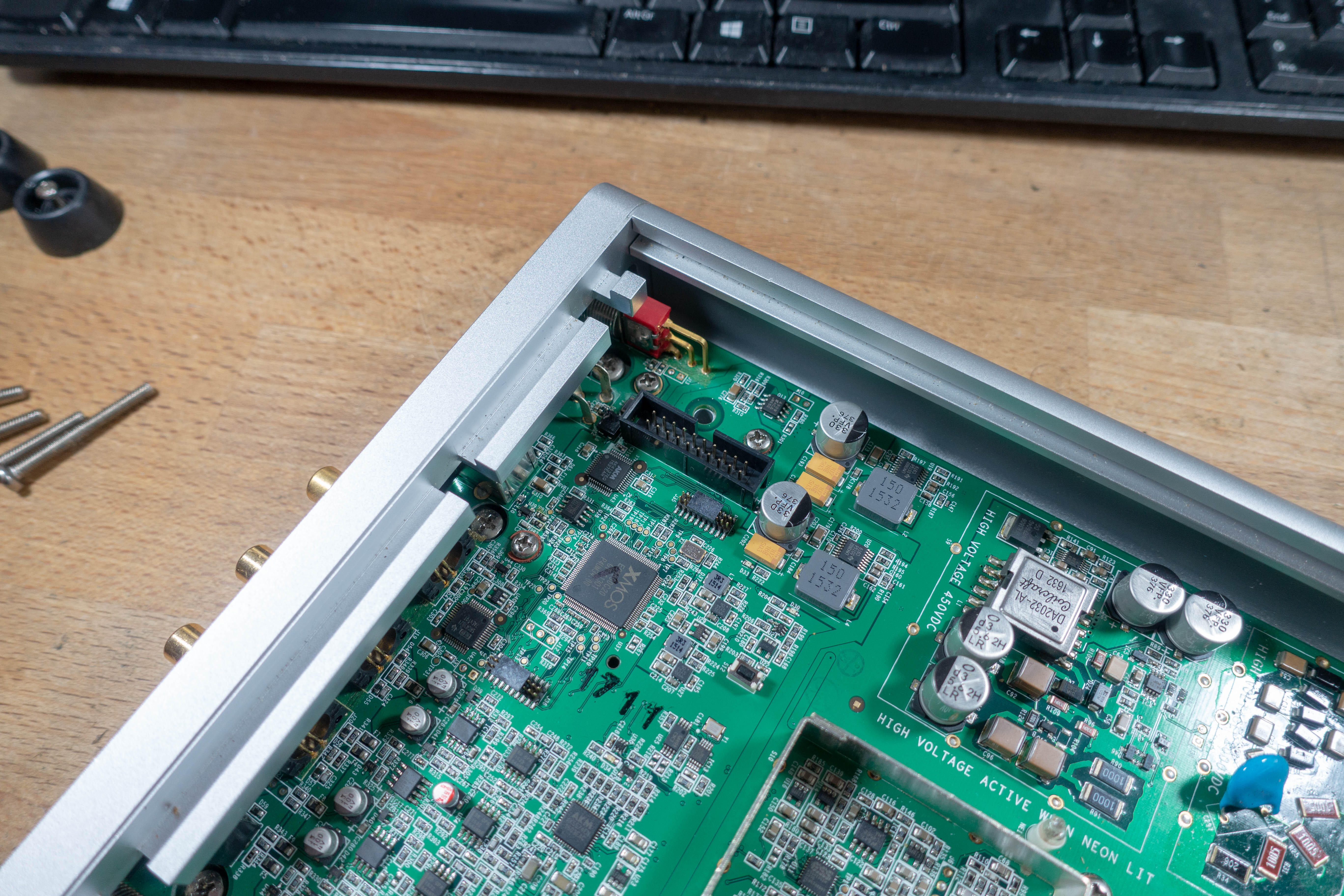
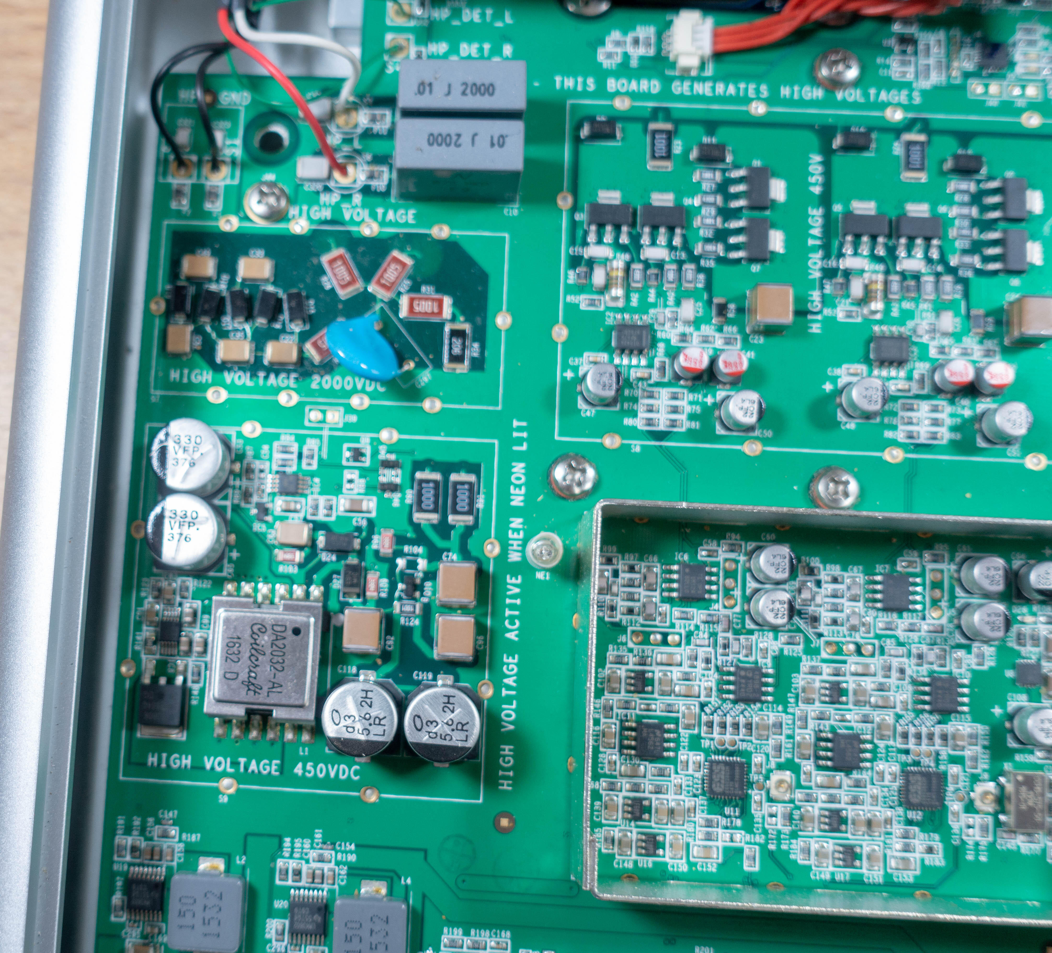
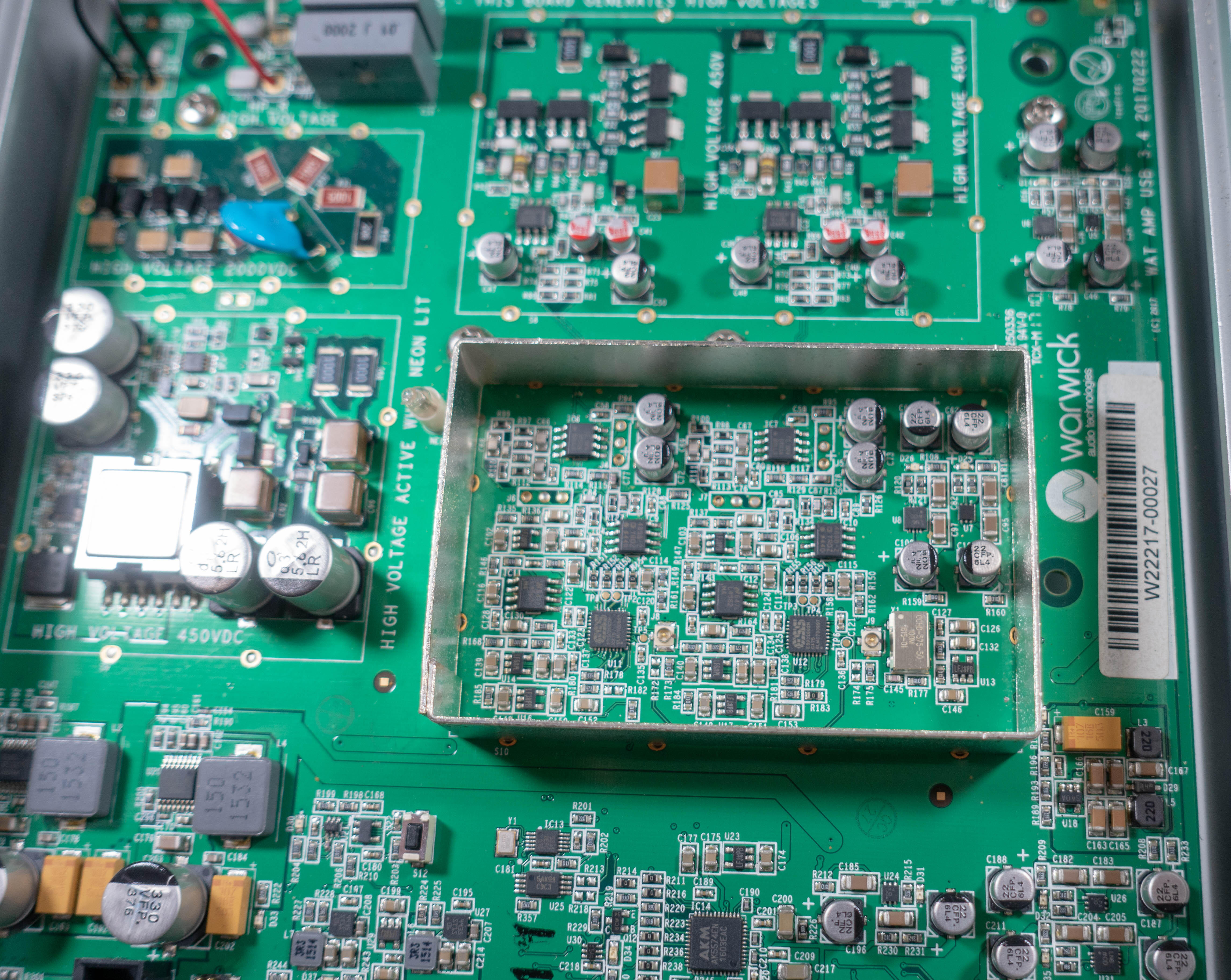
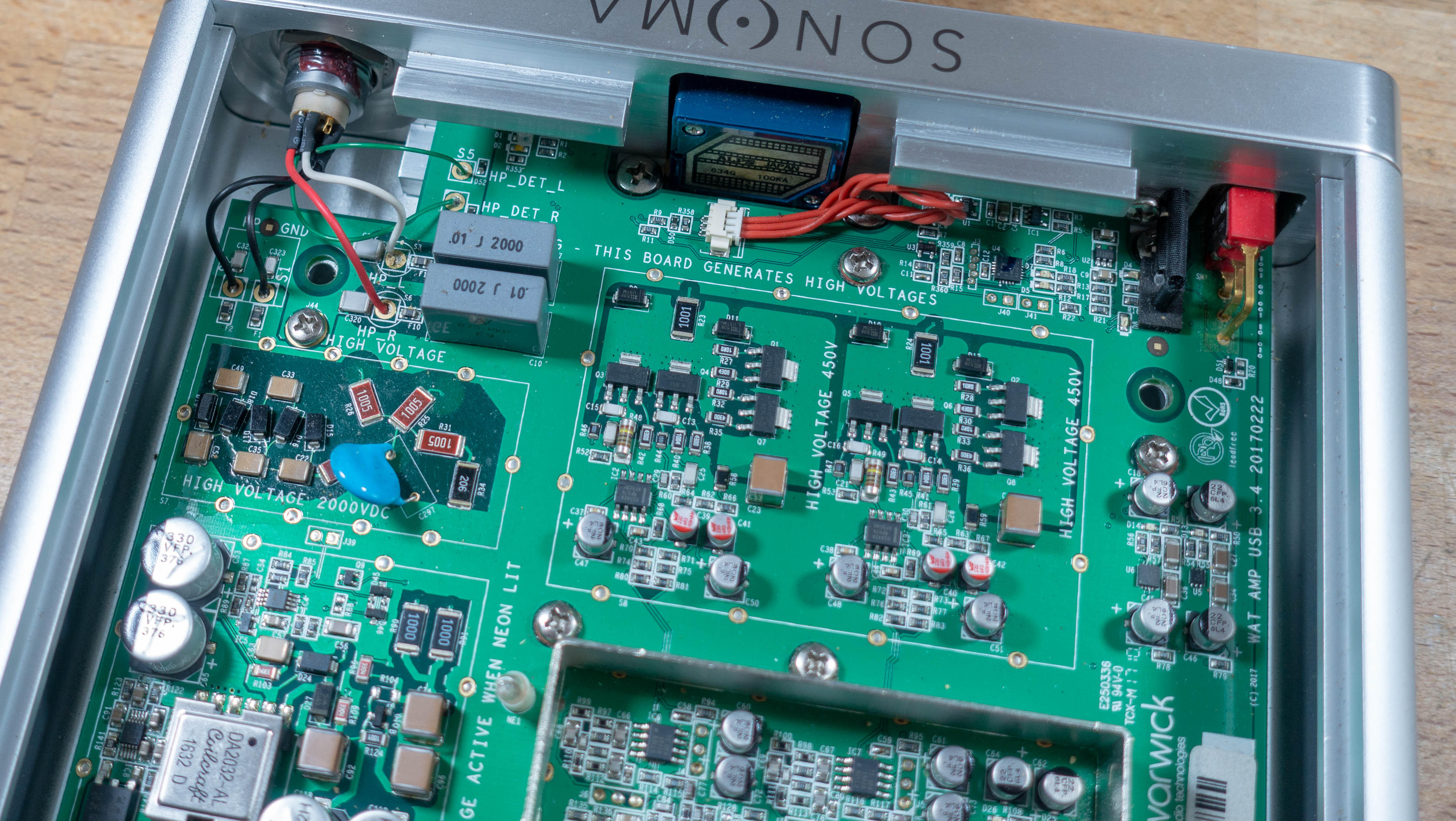
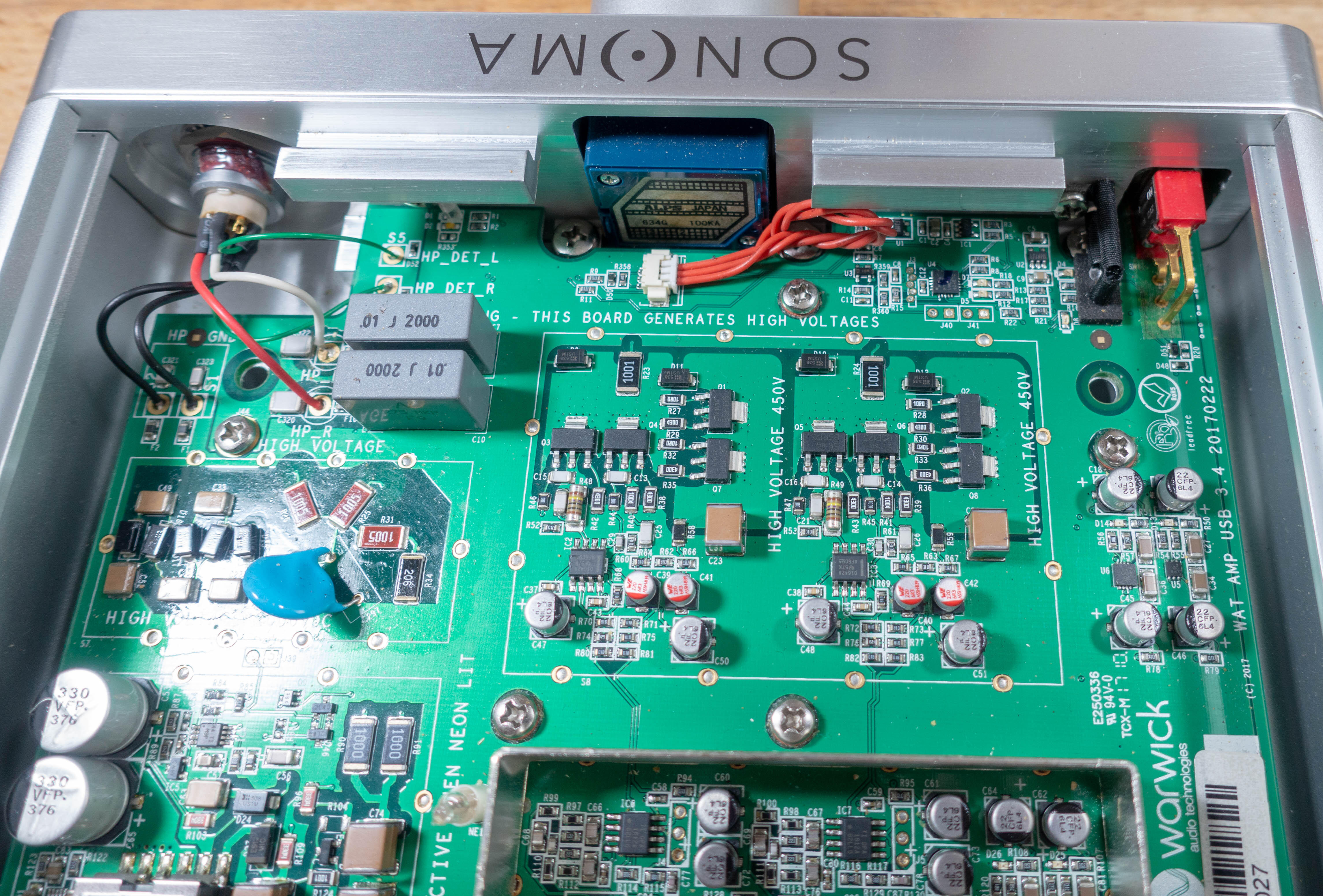
A lot of money was spent on this and the amp is very nicely made in terms of the chassis design. All of the panels are 8mm thick with very nice machining on them but to take all this effort and waste it on a fundamentally flawed driver design... is just beyond me. The analog inputs go through those four dual opamps per side before it goes to the AKM A/D converter. The Xmos unit handles the USB a sample rate converter after it. The SPDIF input has its own sample rate unit too and all of this feeds into the ESS dacs. I always thought these would have a DSP but it appears to be all analog, unless there is a grunty chip hiding on the back of the board that I can't see. That does me we could make our own amps for these if we just clone the filtering circuit and add some adjustments to it. Not sure if there is any demand for that though.
-
-
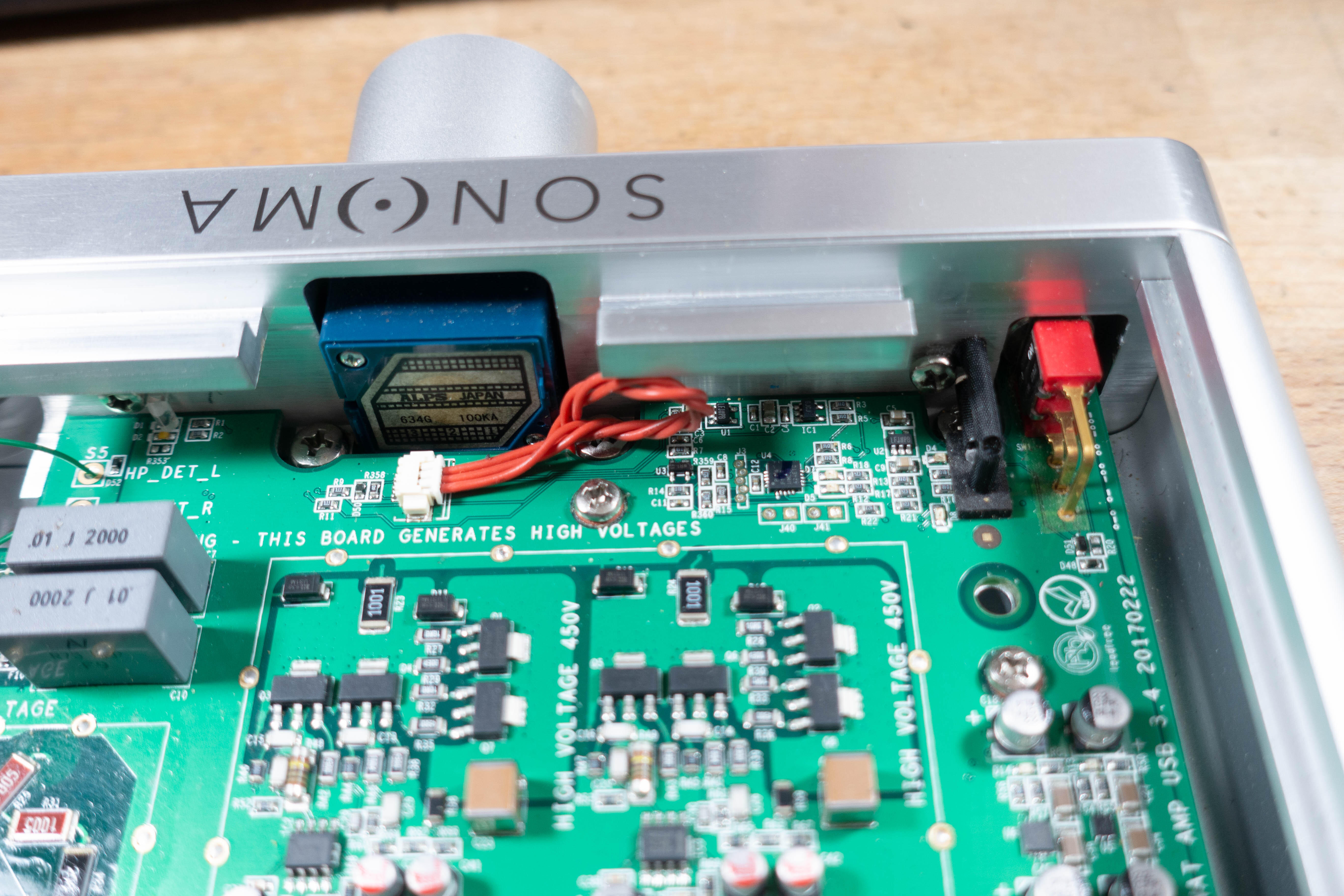
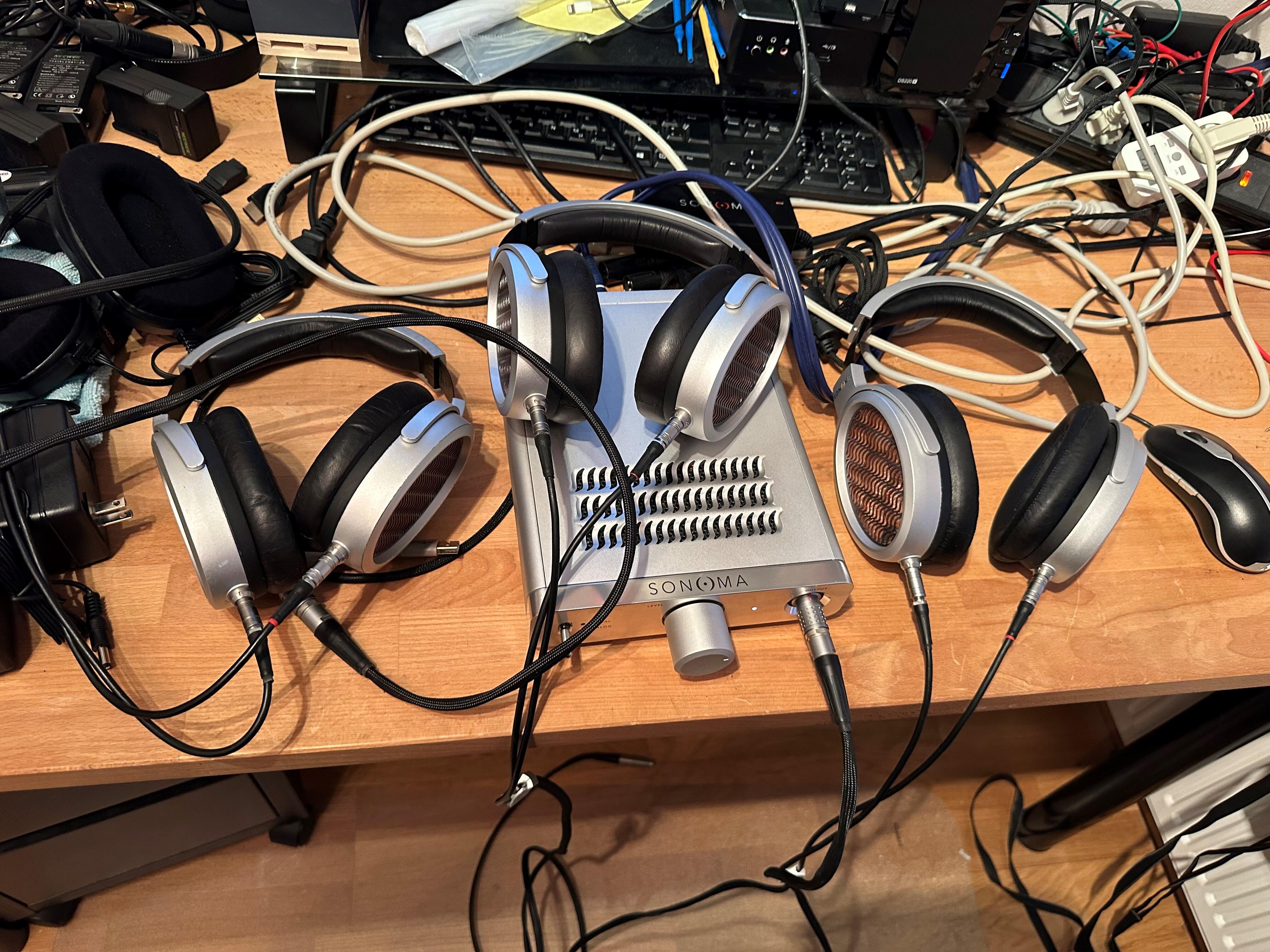
Time for a bump as I found a cheap Sonoma set. My amazing cable tidiness aside, the headphones that came with the set had an imbalance but my other two sets play just fine. One was supposed to have an imbalance as well but nope, just the earpads that were utterly fucked. That seems to be a common thing with these as the materials they used seem to be very cheap indeed so the earpads just fall apart. Now Kevin is already yelling at me to take apart the amp so I'll do that tomorrow. A lot of thought and money has gone into this stuff and quite possibly the worst packaging ever designed... the wank factor is off the scale. The box for the amp is more than 10 times the size of the amp... 2" foam on all sides is a bit too much for such a small unit. I did sit down and listen to them and it is quite an odd experience. Everything sounds a bit fake and the single ended nature means they are as if you have yet to pop your ears... like the sound is further away than it should be. It's quite an odd sensation compared to the normally open sounding electrostatics. It's also easy to hear the DSP trickery going on here and the limited volume on tap is a dead giveaway... I'm almost at max volume with the RCA input and can easily listen at full tilt for an extended period. They also really don't like it when played off the head, you move your head or any transients... the drivers are not happy. Running the drivers in free air creates a lot of audible distortion and they squeal with any movement. Such a shame so much effort has gone into what is at its core, a terrible driver design that has no real purpose.
-
This might be too crazy for me but why not go further. I happen to have a couple of 30kWh, 400V battery packs so a DC-DC converter and make it "portable"?
-
 I can't wait to try them.
 -
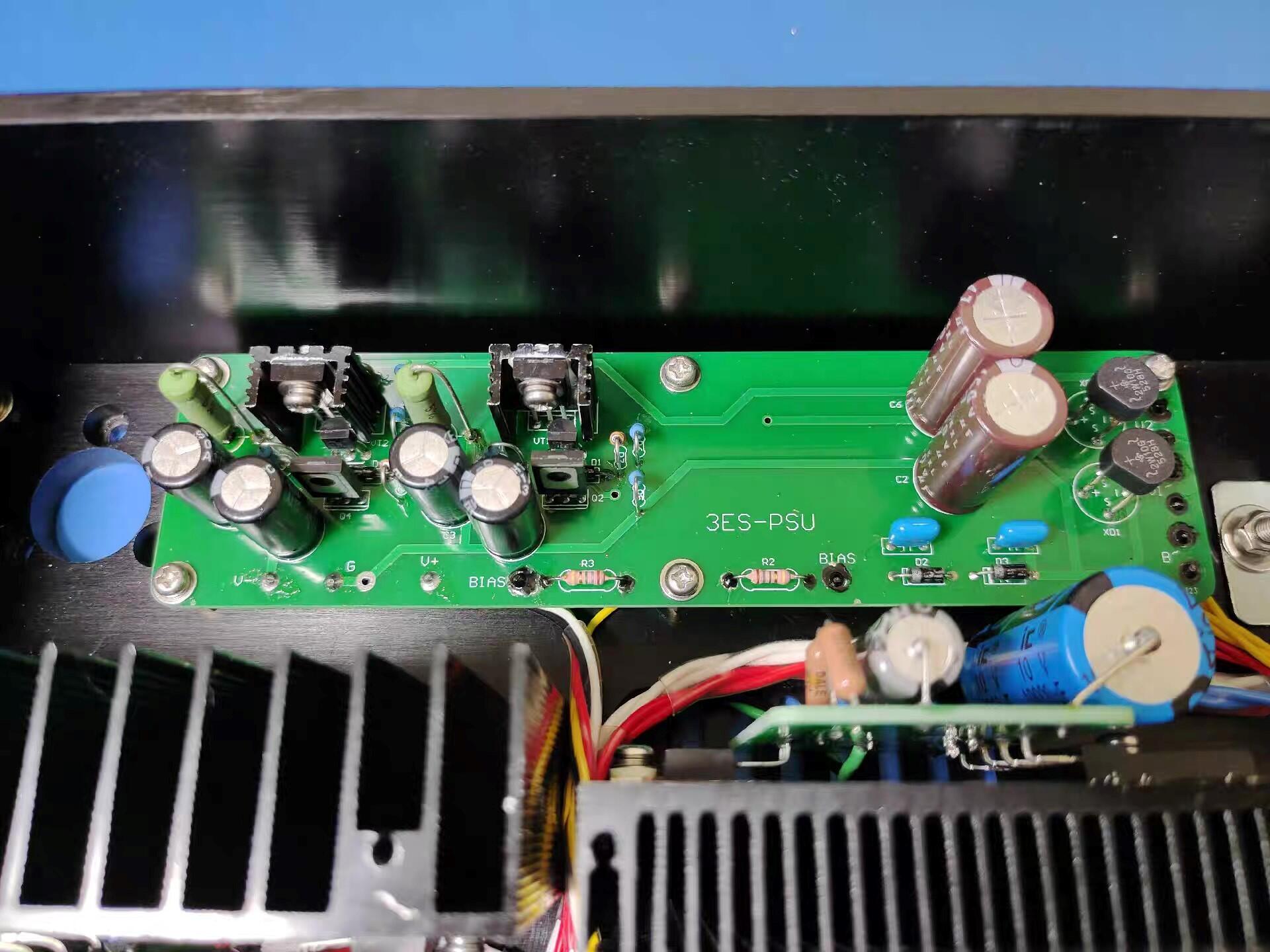
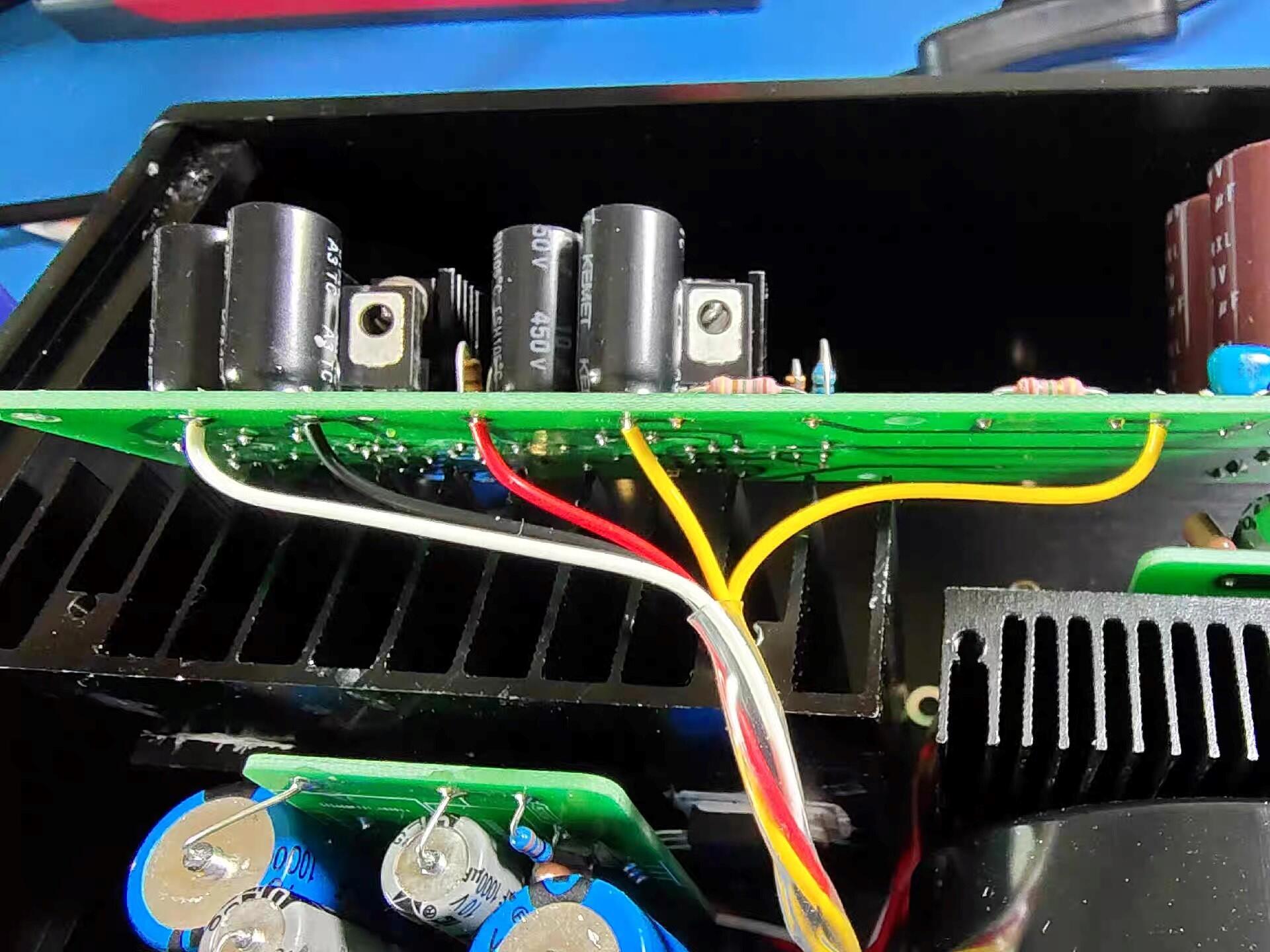
While I was waiting for a flight, I checked out some Chinese sites and found these pics: This is the HV supply for the opamps and the bias supply. This is clearly pretty dire but look at the bias supply... it's simply a voltage doubler off the input AC with no trimmer, no voltage divider, no filter at all but there is more fuckery afoot... look at those bias ballast resistors. Can anybody decode those values? Hint... they are not 4.7M as they should be. 🙄
-
Sure, if you aren't having fun then why on earth would anybody call this a hobby. I know far too many people take this way to seriously but I'd also say his post very much goes in that direction and comes off as nonsensical at best. Perhaps I'm biased by my own extremely low effort reviews but when you are drawing up multiple images... yeah... it all becomes a bit serious. I also very much agree that the review doesn't touch on how the headphones actually sound. To me they have a deliberately compromised imaging (as in designed throw a specific image but it doesn't really work or make any sense) so I feel it is a lot of BS thrown up to try and account for that. Electrostatics are (well should be) infinite baffle designs so if the room is having an impact... then the other side of the bipolar output is surely doing so as well. That will cause cancellations, time smear and totally fuck up the sound. I find it a bit funny how both designs that pay homage to the SR-Omega, leave out or fuck with, what is arguably its main design element. The ES-1a doesn't have the outer screen in place at all and on the X9000 they use a very different material and then angle the screen... and do it in the wrong bloody direction. The screen should have been denser and flat to the back of the drivers.
-
Yeah, seems like that to me as well. Going by the SR-X Mk3 Pro and even the Gamma Pro's... you can get very good performance from such a small driver though. Well it they voice it correctly.... 🙄
-
Absolutely but that might be a good thing. The SR-X was so overly damped it wouldn't really work today.
-
I read through it all and I have to disagree with his findings and it rang alarm bells for me when the room had an effect... yeah no!!
-
I've been away but this one was short lived but really bad. Some 30-40 thousand people lost all heating to the houses (in -10°C weather) and the electrical grid couldn't keep up so they lost that and cold water too in some places. Now another eruption is forecast in 3-4 weeks and that might just be the new norm for us.
- 71 replies
-
- 11
-

-
There SR-X1 drivers are clearly a play on the older SR-XMk3/SR-5N basic structure as seen from the stators but who knows what the structure is actually like. I'll buy a set when they first become available and rip it all apart...
-
I'm all for that if it isn't a cash grab like the X9000. Looks like the SR-Omega... misses all of the design nuances and gets them all wrong
-
Exactly, flip the housing around and remove the stupid dust screen on the L300 and they are not bad at all. Not 207 good but why we have to fix their shit is annoying.
-
The name isn't fixed as of yet but they claim it will be neutral sounding... we'll see about that. It is set to replace the L300 but given it has leather earpads and a whole new structure... I doubt they will be cheap.