spritzer
High Rollers
-
Joined
-
Last visited
Everything posted by spritzer
-
I take a large piece of mylar and do it all by hand. I can get good repeatability but I often stretch 10 diaphragms at a time this way so it's easy to match them into pairs.
-
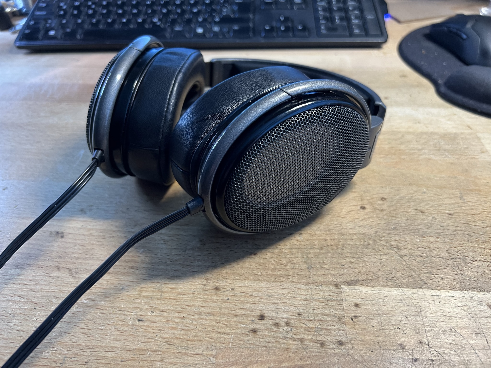
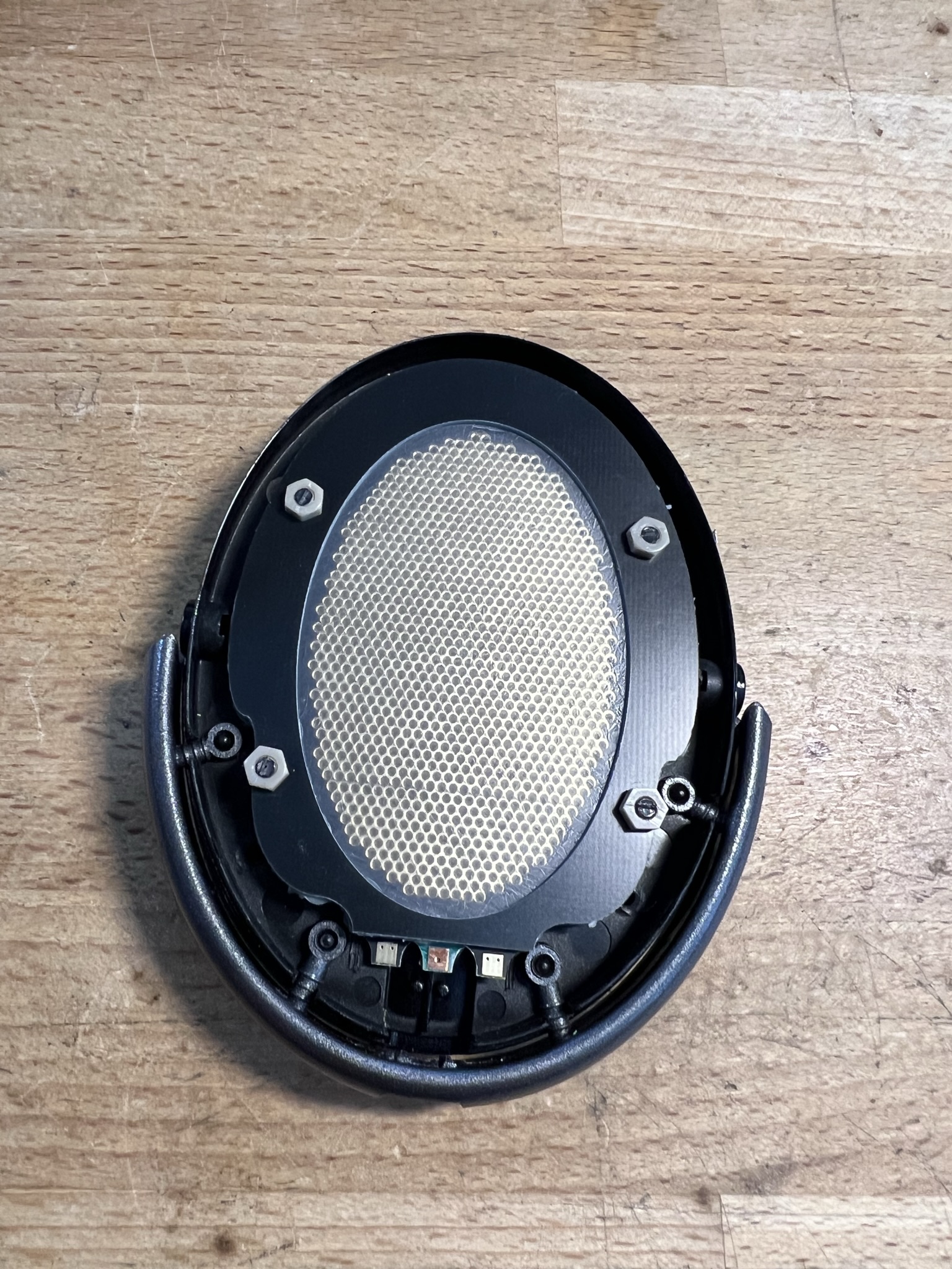
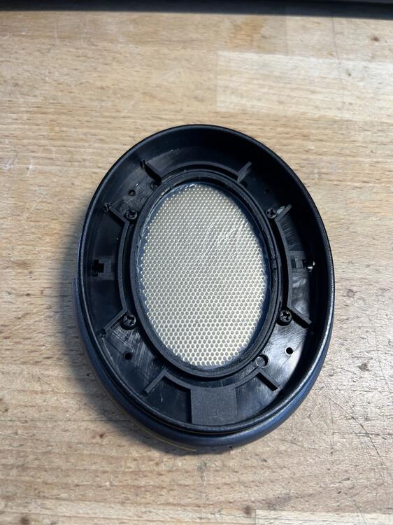
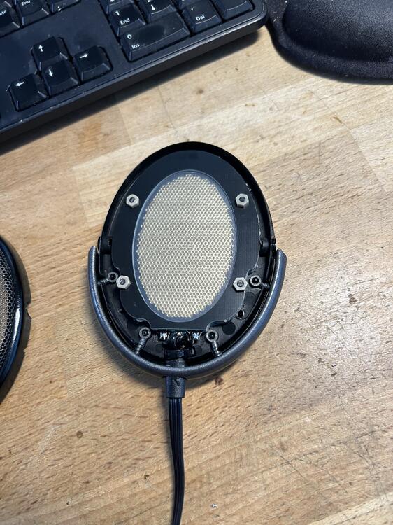
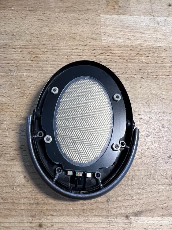
I did search but I couldn't find a dedicated thread about DIY electrostatics so in the spirit of getting the discussion started, here is something I've been working on. Well over a decade ago I bought up all the spare Sennheiser HE60 parts to assemble new headphones. The first thing to go out of stock was the main housing so to assemble the last pair, I had to adept a HD650 housing to take the HE60 drivers. Ever since then it has stuck in my head to make my own drivers for those housings and well... here is version 2.0: I bought a ratty old HD650 and completely stripped it apart. Headpad, earpads and cable went into the trash while the rest went for a long bath. First step is to make the baffle flat so a lot of cutting with nice, sharp, flush cutters. I naturally forgot to take a picture of that step... Next step was to fully measure what area I had to work with and design PCB's to match that, while maximizing the open area. The end result is three different PCB's, as they are all setup to be dual sided. One for the stators, one which holds the diaphragm and finally the simple outline which holds the dust covers and can act as a spacer. Some pics of them assembled in the housing: Four nylon screws hold the sandwich together, fixed with PEEK nuts to get extra gripping power as the assembly had to be as flat as is possible. Dust covers placed away from the stators so they don't cause any issues. Earpad side: Due to the screws, some earpad mountings have to be cut up to get the pads to fit but yeah, they are just cheap crap from China so who cares. I could cut a slot in them to try and make it fit but maintaining as much pressure on the drivers as I can is far more important. Final assembly with a King Sound cable as I have a couple of those sitting around. For the diaphragm I used my usual stock of 1.4um film and the earpads are just the cheapest leather pads I found on ebay. I have a couple of nicer ones but these are the thickest and that helps make them more balanced sounding. The diaphragms were stretched by hand on a mirror (which is my preferred way) and glued with wood glue (thanks for the tip Aumkar!) which is just perfect for this. Coating is anti-static spray which means they energize in five seconds or so which I can live with. Now for the sound... pretty damn good for something so simple and literally being the second set I assemble. Well that and zero effort has been put into sealing the baffle or just any sealing at all. I just stuck the PCB's onto the baffle and built up the stack. Overall sound signature is similar to the HE60 but not as diffused and with far more bass output. Maybe a tad too much at times as there are some oscillations that I can pickup at very high volume levels and under high excursion. I tend to go with slightly less tension on the diaphragm so that might be it. Treble is very pronounced with the thinner pads but with the ones pictured, it is just perfect. These are not forward at all and the soundstage is excellent for this size of a driver and non-angled earpads. Sensitivity is slightly lower than the regular Stax sets but still only marginally so. All in I'm very happy with the roughly 150$ outlay for these. Now this is version 2.0 but the first version used a HD58X from Drop, brand new in the box that I cut up. Same driver profile but thicker stators so the efficiency was really bad plus the stators had full solder mask on them. Now I'm out of the spacer PCB's for the dust covers so next time I order PCB's, I'll make another set. I also have some diaphragm spacers which would work well for normal bias as I've always wanted to mess more with that.

-
They are identical in every way, just the color of the housing and the embossed logo in the headband differentiate them. Stax serial numbers are a complete bust, you can have a very early set with almost the same serial number as nearly new one.
-
There is no Stax mafia....
-
I must say this is a pretty shit attempt at trolling but what the fuck is a torus and I most definitely don't use that...
-
I only spent a few minutes with it using the new DCA and Shangri-la SR with an unfamiliar source so I can't really comment on it. No issues I could hear but I'd need to spend some more time with it. It's an impressive beast though. I forgot to mention I also tried the Warwick Audio Bravura... what a piece of shit that is. Now the amp was broken so no high gain mode available so I couldn't push the volume far enough. Still it is the blandest sound imaginable, it does nothing well and you can clearly hear the DSP doing its best to try and fix the sound of the single ended transducers. I suspect this will be far worse when the volume is pushed to normal levels. I actually have a couple of the Sonoma M1 headphones (dirt cheap now) and was planning on designing an amp for them (the Bravura uses the same amp) but I might not bother. They clearly can't work with a direct signal so my plan is to just reuse the housings and design proper electrostatic drivers that fit in there.
-
It's a bit amazing how people like this are like leaches on the industry. I did a little bit of digging and yeah... found this: https://www.startengine.com/offering/danclark So sites like these are iffy to say the least and a good way to be utterly fucked as the investor and why would any legitimate company go down this route. There is Bluto himself singing his praises...
-
There was at least the combo board with the TKD 601 as well
-
Well he's right about one thing, a 6SN7 feeding a 300B hasn't got a hope in hell of driving electrostatics simply because of the voltage gain. Why anybody would want to use 300B's for this role though when the 20B exists is beyond me.
-
It needs more mil-spec gold anodizing... 😉 I tried to listen to the Viva a few times but it was always occupied. The fact that they use Rifa caps for coupling, the same type which is notorious for failing short as X and Y caps in PSU's... yeah this is not a good thing. It was awesome seeing everyone and totally worth it for landing back home this morning running on 23 hours with no sleep. I didn't try a whole lot of stuff other than the DCA headphones and I tried the Hifiman Shangri-La too out of the Headamp amps. What a fucking waste of time that thing was, did a direct comparison against the Audeze CRBN and it failed in ever regard, didn't do a single thing better than the CRBN's. It is vague sounding with no real impact and being Hifiman... built like absolute shit.
-
I'm happy that at least got him to stand up and move from that fucking chair... 😉 It was funny to see the difference compared to other vendors who had perfectly affable people working there and this shit show. I wonder if DCA is doing the Cavalli route, have some idiot show up with an investment and blow through all of it and move on to the next sucker? But vaping in and around delicate electronics like this is beyond stupid. What does think is in the smoke, magic fairy dust that makes electrostatics better?
-
Yeah it has SE and balanced inputs and a volume control. Could be a simple chip amp feeding some transformers which is very popular in China now. As for why Stax stopped making transformer boxes, it doesn't make any sense to do so these days.
-
I listened to the Cortina three times, twice off a BHSE and once off the new GC amp. Unfamiliar sources are an issue plus regular meet conditions but there was something about the midrange that bothered me, like an etch to voices which came off as very artificial but I need more time with them to nail it down. I also feel that headband is utter trash, on the second time I put them on my head the headpad caught on the metal springs causing the headphones to make a very lough "twang" sound through the earcups. I prefer the older type on the Voce, seems much more solid and better made. I'm also not sure if these are worth the price, just put them next to the CRBN and it looks like some cheap fake out of China, The headpad and earpads feel cheap and nasty and not high end in any way. This is always a personal thing but they were both sitting in front of me and they don't look, or feel, like a comparable product. The biggest issue for me though are the people who were there from DCA, I mean fucktards doesn't really cover them. I know fullwell I can be brash and bombastic but these people are utter fucking idiots. I went to their table to try the Voce and wanted to know when they were fixed as the original release of the Voce... they were fucking awful. This earpads never made any sense and it's clear to anybody who has messed with electrostatics for s long time. Same issue as with the King Sounds back in the day and they now, too, have moved to new earpads. Now the guy there, who was quick to point out he was the president of the company, said this gem when I said the Voce was awful, "Ohhh you like electrostatics so you don't like bass!" Yeah... and he also wanted to ask if I had ever designed headphones and when I started to listen, he ran over to Justin to bitch about me... which I heard most of. What a fucking idiot. Then we have the lady who was there, when I said matching of earpads was stupid loudly said this "SIR, THEY ARE HANDMADE!!!" Well fucking duhhh, all earpads are handmade outside of the molded ones super cheap ones. Most of my life I've been making things by hand, which have to be extremely consistent and it is easily done with far worse materials than these. Now I reached out to two manufacturers and asked if they had measured earpad effect on the sound. 0.1-0.4dB is worst case and with large production runs of earpads they are much closer. So the bottom line, the people making them are fucktards but I need to spend more time with the headphones. I don't feel they are worth the extra cost over the Voce, which looks much better made, and now sounds far better than they did. Add to that the Audeze CRBN being sold as B-stock for less than 3k$ and this becomes a pretty hard sell.
-
The KSE headphones are great but the amps are trash. Luckily China has us covered as you can get them now fitted with a Stax plug for very little money. Don't use them on Pro bias though, only normal bias outputs.
-
Yeah,I'm not so sure about this one but naturally it will be ripped apart.
-
Hehe, the jetlag is killing me too plus the general NYC issue of "walkingtoomuch". I'll be at the meet 10am sharp though
-
I look forward to trying these out but the damping does make the worried. DCA feel the need to add damping to everything while being shit at doing it, I mean the Voce was pretty much terrible in ever way. Also the matched earpads has to be the stupidest shit ever, this is worse than Hifiman levels of utter BS.
-
I've landed in NYC but no plans set for tomorrow. We almost died from too much pizza at John's plus I've been up for almost 24 hours...
-
Any noise which changes with the volume control points to a source issue as the volume control is at the front of the circuit. The noise is being amplified and attenuated with the volume control. Could also be a ground issue as that would tie into the volume control as well
-
Indeed, the rails are just not high enough. Even the old SRM-001 has a single 600v rail for the output
-
The specs, go read the datasheet. Because Stax, under Chinese control, doesn't give a shit? The D10 and D50 have very little to do with Stax in Japan.
-
I'd take a transformer solution, that is properly driven, over the the Apex garbage. Just look at the specs of those modules, they are truly terrible.
-
Yeah, it's in many ways worse to have an external PSU but let's not get some actual engineering involved here. Go buy the Woo 3ES with a 500$ opamp electrostatic amp. That is 14K$ all in and has an external PSU... well kinda as they saw the need to have the power transformers right next to the output sockets.
-
The Koss unit draws 9W from the wall, max so factor in PSU losses, very high rail voltages, that you driving 4 amplifier channels and yup, there is not a lot of power there. So Woo has a new electrostatic amp out, WA7e... who wants to guess that it is a tube pre driving some Apex modules?
-
My friend has tagged along for the trip so I'll have to check with him but I'm sure we'll up for something on Friday.