JimL
High Rollers
-
Joined
-
Last visited
Everything posted by JimL
-
Glad your wife likes the SRX Plus.
-
It's a totally differential circuit, so a single ended input automatically gets converted to a balance output - you are using both sides of the output regardless, so that wouldn't work.
-
-
Looks a lot like the front end of an electrostatic headphone amp (T8000-ish), but with relatively low voltage transistors (except for the KSA1156). You could always substitute a MOSFET current source for the input tube tail CCS.
-
So, it was shown decades ago that 5-10% high filament voltages will decrease tube life. On the other hand, running your filaments 5=10% low will not affect cathode emissions much. 6SN7 tubes draw 0.6 amps each, or 1.2 amps for a pair, so an 0.5 ohm resistor will drop your filament voltage to about 6.2 volts, while a 1 ohm resistor will drop it to 5.6 volts. Somewhere around 0.7-0.8 ohms should do it - a wire wound resistor of those values is pretty inexpensive.
-
So the major issue I have with the Trilogy is this: given the tube complement, the only possible circuit is the Egmont topology shown in spritzer's post of August 27, above. This is the simplest, cheapest electrostatic amp circuit around, similar to a circuit that Schiit considered building as a CHEAP electrostatic amp at one point. As best I can tell from internal pics that have teen posted, the Trilogy doesn't even have output constant current source loads, which make a big difference in drive capability. congo5 has built two Egmonts, and modified one by substituting constant current source loads for the plate resistors. He reported that: "Having two Egmont's I can A/B them to compare. It is a huge improvement, more volume and much less distortion. Much more of a usable amp now. Noticeably cleaner bass. Like Night and Day." So, an Egmont type circuit would be reasonable for an amp selling for, say, $1000, or 800GBP. No way is this worth what Trilogy are asking for it. And as far as sound quality, here is a show report from Head-Fi by someone who owns a KGSS Carbon and SR009: "Stax 009 + Trilogy Audio Amplifier This was introduced as a ground up new design with all tube line stage. It sounded better than the T8000 but not by much. Nice enough but not excited yet. I get a wow moment at home on my Carbon. Not hearing that here. The soundstage is nothing special. Looking in the top grill out has 6 tubes set horizontally. It was not as warm as my Carbon on the case / top. Think it costs 5K. Nice to see a UK produce, and I wanted to be wowed but not happening. No USB port so listened to Diana Krall and some Jazz." If you like the sound quality, fine. But honestly, for the price I think it's a rip-off. Sorry.
-
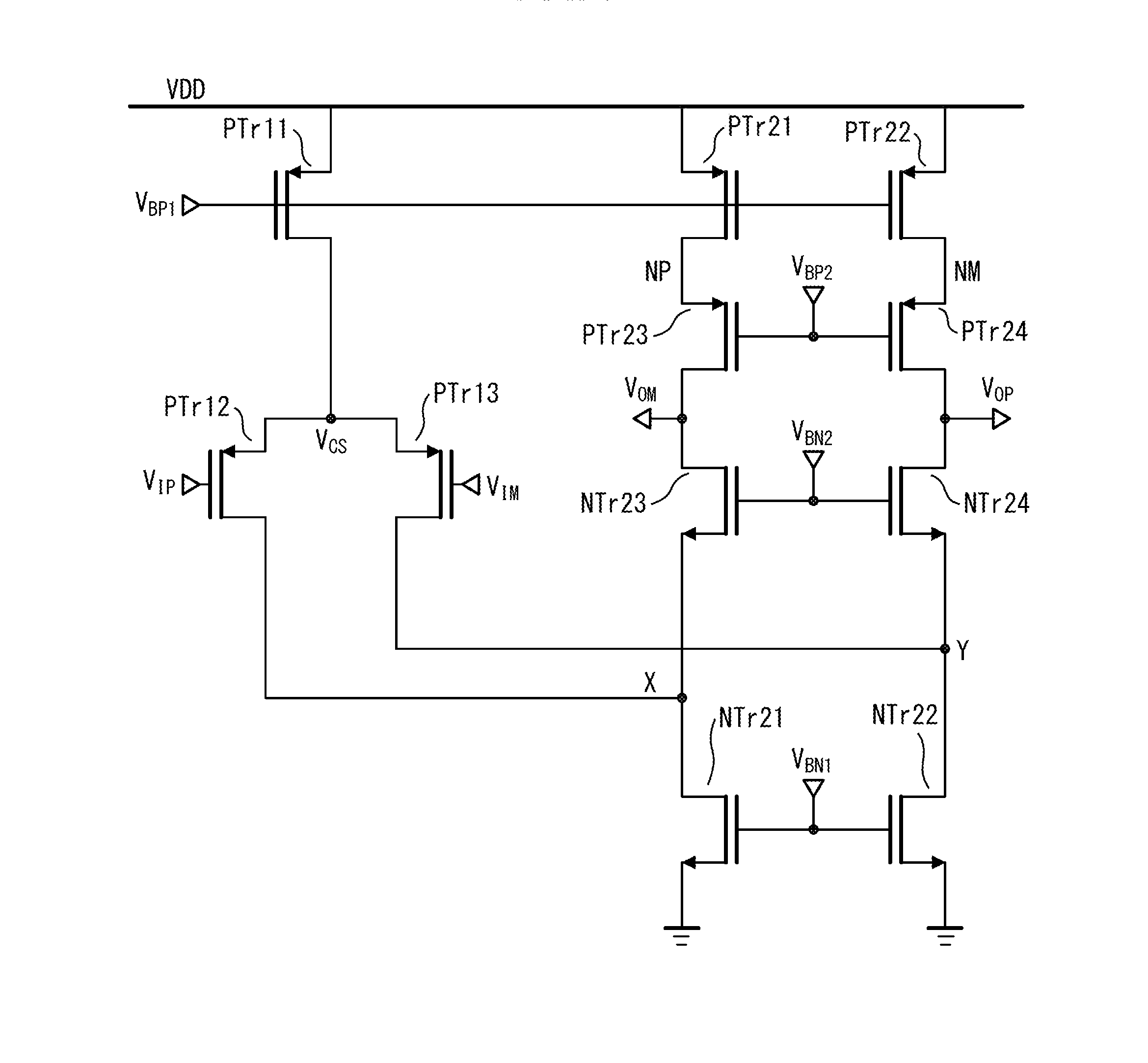
Hmm... Let's see. Topology described as: BJT Folded Cascode+Tube with CCS, 6SN7GTB outputs. Max output 325 VRMS which calculates to 920 volts peak-to-peak - this suggests PS supply of around +/-300 volts give or take. So I Google searched folded cascode and came up with this image from a patent application - looks similar to the input and mid-stages of a Stax amp, but maybe with BJT input instead of FETs, and the CCS looks cascoded, so probably the output stage is similar to the SRX Plus, but without a tail current source. So, yeah, overall similar to a SRM-T1 with CCS in place of the output resistors, or a KGDT/KGST. Most likely passive PS, though.

-
So, the problem is, even if the DN2540 sits at +300 volts, with signal, it can swing anywhere between ground and +600 volts with a big enough input signal. But the DN2540 is only rated at 400 volts. You should be able to see where I am going with this. Furthermore, as Kevin Gilmore points out, there is nothing in the circuit that sets the drain voltage of the DN2540 at +300 volts. The 10M90S current source is pretty much indifferent as to what the drain-source voltage of the DN2540 is so there is really nothing to control the quiescent voltage of the DN2540 drain. The feedback resistor really won't control it. I saw this in the SRX Plus, which uses 250k feedback resistors - there were times during de-bugging and adjustment when one output was nearly at B+ whereas the other was close to B- until I got things tuned up. That is tolerable with tubes because the maximum tolerated voltage is higher than the maximum rated plate voltage. Not so with MOSFETs or transistors - exceed the maximum for even an instant and you have a fried device. If that happens to your circuit on turn-on, it'll blow so fast you won't even know what happened. Take a closer look at the HEV70 schematic, it looks like there is a resistor network to set the quiescent output voltage.
-
What I'm confused about is, why would you want to build a so-so amp just to try things out? It seems to me that a better solution is to get an old Stax SRD-6 or 7 adapter box, modify it to pro bias and drive it with a standard speaker amp. That is a known quantity, will be easier, have at least decent quality sound, and probably less expensive.
-
Never going to happen. As Dirty Harry said, "A man's got to know his limitations."
-
As I recall, that's the circuit that you tried to build, but found the OA2 tubes lost most of the signal?
-
Weren't you going to run a simulation of the SRX input circuit to see if its amplification was similar to a standard cascode circuit? I'd be interested to see what the results of that was. As to the DNA issue, the SRX has a differential/long-tailed phase splitter input stage with two tubes sitting one on top of the other with the plate of the bottom tube connected to the cathode of the top tube (ignore the cross-coupling for a minute), and an output tube with the output taken off the plates. These features are broadly similar to the T2 in topology. The differences between a banana and a human is more akin to comparing a transistor radio to a T2.
-
Again, we are going to have to agree to disagree on description of the input stage. D.R. Birt, who first described the circuit in Wireless World, calls it "long-tailed pair using cascode stages with cross-coupling." Yes, there are additional stages in the T2, and the output stage uses grounded grid drive, but I maintain that the relation between the two is akin to the relation between a velociraptor and a T. rex. You can see the common DNA in the two.
-
Congratulations, indeed! Now, as you may know, the T2's backbone is the same as the SRX Plus, it's just difficult to see because of the forest of solid state parts that surrounds it, most of them to replace two capacitors (per channel) in the SRX. So, now you need to build the SRX Plus and see how cheap and simple you can go and still get great sound.
-
I was going to suggest the same thing, thanks. That's probably where anyone interested in an SMD Carbon would look first, anyway.
-
No problemo.
-
Yes, I recommend floating the heater supplies. The input tube and output tube heater supplies also need to be separate, even if you rewire the input heater supplies to 6 volt.
-
Or you have more 12AT7 problems.
-
Hmm. Well, no. My prototype is single ended with the negative input tied to ground (I don't have any balanced sources, only single ended), and the plates voltages are equal. In fact, the original Stax SRX circuit has the negative input grounded. If you have a single ended input, you should balance the plates with the volume control turned all the way down.
-
The advantage of a simple circuit is there are only a limited number of things that can go wrong.
-
First, I would take the 12AT7 tubes from the bad amp and substitute them one at a time into the good amp. If the tubes balance in the good amp, then they are not the problem. While the tubes are out, you can re-check the plate resistors to make sure you didn't somehow put in the wrong values. Assuming they are good, that leaves the tail current sources. If that is the problem, I would replace all the DN2540s in both input tail current sources.
-
Hey, it's a German extension cord - gotta keep those unruly electrons in line!
-
I used something like that ground loop breaker for my phono preamp.
-
Tube OTL amps are best used with high impedance cans as their output impedance is relatively high, in the case of the Menace I estimate around 50 ohms. If we use a Sennheiser HD600 300 ohm as an example, it is specified as 102 dB/volt, so 10 volts will give a deafening 122 dB. Looking at the pics, I think the output caps C6 and 7 are motor run caps, as is C5 (note that all of these are rated at 370VAC, whereas C4 is likely electrolytic as it is rated in DC volts).
-
RSA is out of business? Just looked up their website, and there is a list of Christmas specials dated 10/17/17.