PretentiousFood
-
Posts
116 -
Joined
-
Last visited
Recent Profile Visitors
3,404 profile views


PretentiousFood's Achievements
Limited Edition Bronze Participant (4/6)
82
Reputation
-
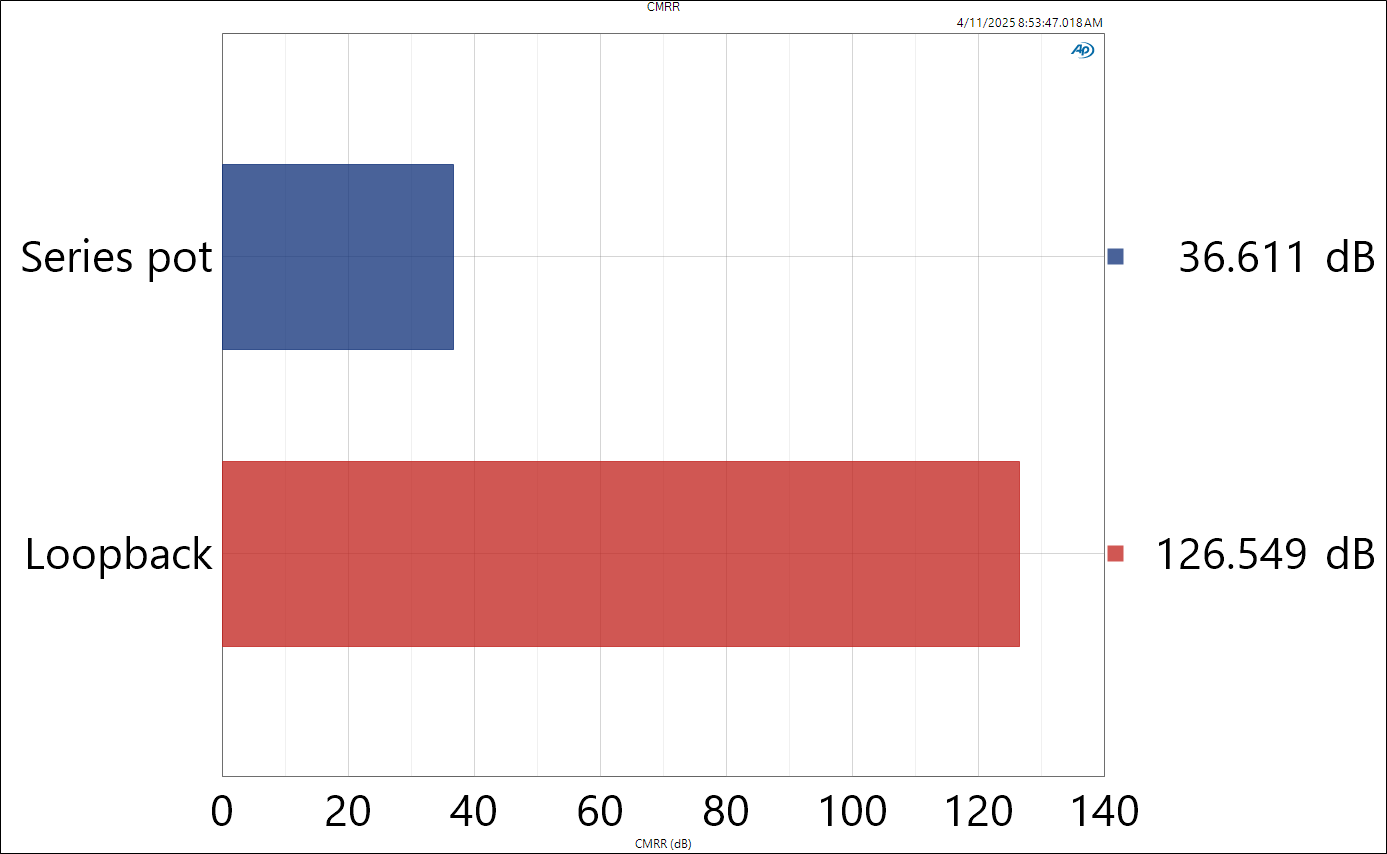
I was also surprised to only get 16dB at min with the series pot. To take the measurements in my last post, I did connect the pot as you describe, as if it were the input of an audio amplifier. To make the measurement, the analyzer sends a balanced differential mode signal measurement, then switches its relays to output a common mode signal and measure the output. It then calculates the ratio of the DM measurement over the CM measurement. With the pot in the minimum position, I'm guessing that the DM signal is attenuated enough that the noise floor eats into the measurement accuracy. There's some 40dB (!) of CMRR degradation on the shunt pot configuration as well at the minimum position. To test the theory, we could boost the test signal level... But I feel confident enough to say that the shunt pot offers better CMRR without repeating the measurements.
-
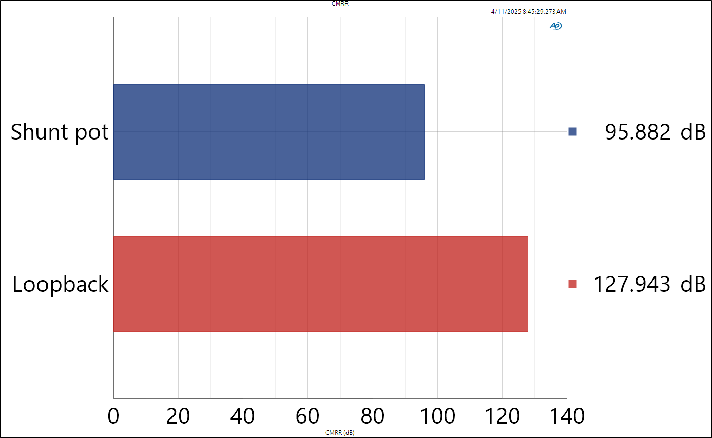
I think you're right-- thanks for picking up on this. I do still think it matters; if the CM signal is getting converted to DM, the system's CMRR will be limited, no? Bill Whitlock of Jensen makes a big kerfuffle about balanced impedances. Here's an AES presentation that you may have seen. It's a bit goofy, but gets the point across. https://www.aes.org/standards/webinars/AES_Standards_Webinar_SC0505_20210726.pdf If I'm being honest, I didn't realize there was a CMRR test. 😁 I'll be using this more often. It can't do sweeps and I don't think it can append results in APx500 v4, but here are some results tested at 1kHz with a 1VRMS signal. I tabulated some data at different positions. Looks like there is a "sweet spot" with the conventional pot hookup, whereas the shunt pot does very well once you clear the first few degrees of rotation. Position Shunt pot CMRR (dB) Series pot CMRR (dB) Min 50.800 16.024 77.772 23.607 89.748 27.03 99.328 29.009 98.410 30.802 97.917 39.849 97.656 73.718 97.362 67.308 97.228 40.310 96.271 35.341 95.442 30.717 94.715 32.493 94.031 45.187 Max 93.844 86.054

-
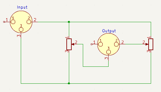
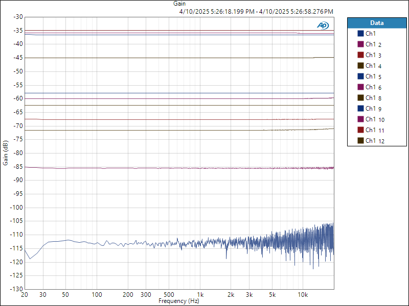
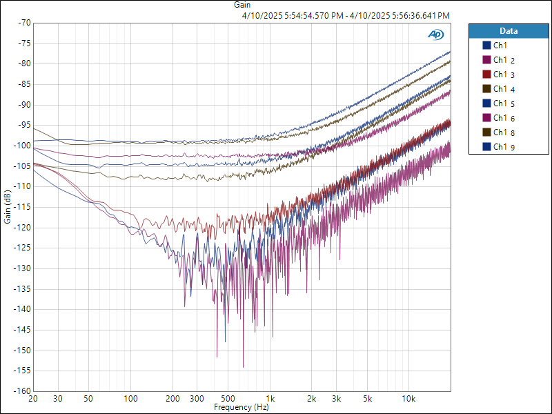
I may be a hack, but I switched from using 4-gang pots to shunting stereo pots because I think they work better. A big part of the reason why I would build a balanced circuit is to benefit from its CMRR (and even order distortion cancellation by proxy). I measured the matching between gangs on a 20k RK27; it's better than the specified 20% tolerange, but it's not great. Here are some measurements at arbitrary rotations. Gang A Gang B Matching 51.4 51.6 0.4% 255.7 252.8 -1.1% 623 624 0.2% 1299 1300 0.1% 3042 3089 1.5% 4230 4368 3.2% 8470 9080 6.7% 14680 15420 4.8% 19100 19930 4.2% 19900 20380 2.4% The matching is directly proprotional to the CMRR. So I took a measurement of CMRR using the following circuit. The idea is that this simulates the balanced input of an amplifier and will tell us how balanced things actually are. Not very, it seems. Each trace is a different rotation angle on the pot, with the -115dB one being with the signal fully shunted. (There is some resitual resistance with the pot at 0.) -35dB of CMRR will significantly degrade an amp's performance. I repeated the measurements with a shunting pot configuration, using Yageo 1% 2k resistors and the same 20k pot. Although the AP input capacitance degrades CMRR at high frequencies, even the worst 1kHz measurement is about 12dB better than the best measurement with the series pot. The low frequency degradation is most likely caused by the AP's 1/f noise-- we're measuring microvolts at this point. If I wanted to further improve performance, I'd use resistors with better matching. The Vishay ORN arrays are available in 0.01% and would probably be my pick. LT5400 isn't bad either. https://www.mouser.ca/ProductDetail/71-ORNTA1001ZUF I don't know that this is necessarily relevant to the design in the first post-- looks like it doesn't use a pot at all-- but the circuit has its place.
-
I guess this is what SRM-700T looks like.....
PretentiousFood replied to hyperma's topic in Headphone Amplification
I don't think I've ever seen an SRM-700T in the flesh, but I've had pretty lousy experience with the Nexperia duals. I tried the PMP5501 and NSS40300 matched pairs as input buffers to drive a differential pair, and measured a 1/f corner as high as 5kHz on the NSS40300. Both were too noisy and had audible tape-like noise. Used in a differential pair with this much gain, I'm sure the noise is much worse. 1/f noise is generally a result of wafer contamination at the fab; maybe these other parts are made on a cleaner process, but the Toshiba parts are very quiet. If we want JFETs, the JFE2140 is pretty compelling. Much tighter matching than the LSK parts, and a bit cheaper, too. https://www.ti.com/product/JFE2140 -
finally an electrostatic transportable
PretentiousFood replied to kevin gilmore's topic in Do It Yourself
Have you tried measuring the noise from V+ to V- when the pair is stacked? I ran into trouble stacking low voltage Mean-Wells in this manner; not sure if it's the slightly different oscillation frequencies from unit to unit, the stray capacitance, or something else, but it's significantly worse than when measuring a single unit. A good workaround if this proves to be troublesome is to place a common mode filter on the output of the SMPS, and to stack the outputs of the filter rather than the SMPS V+/V- pins. This eliminated noise that differential mode filtering and regulators couldn't take out in a couple of my builds. I've found that I need a fairly large value CM choke and cap, at least 50mH for the choke and upwards 1uF for the cap. These Kemet parts have worked well for me. That said, perhaps these don't need them at all. -
KG Balanced Dynahi build discussion thread
PretentiousFood replied to Vortex's topic in Do It Yourself
If you don't mind downloading a 25mb pdf, the National FET Databook actually shows the dies. Some aren't perfectly symmetrical, so while they'll work in either configuration, I'm guessing they could perform slightly differently if D and S are flipped (e.g. process 88 shows more surface area for the S than D-- might impact gm?). http://bitsavers.trailing-edge.com/components/national/_dataBooks/1977_National_FET_Databook.pdf -
I would probably skip the feedback and cathode Rs (which reduce gain and increase rp), and use a lower mu, lower rp tube like a 12AT7. If you do want to stick with the 12AX7 and nfb, they really do benefit from a plate load several times greater than rp, which shouldn't be too hard to pull off with an lnd150-based gyrator. The DN2540 only really shines at quiescent currents above 10mA or so. Something like a BSS126/DN2540 cascode or LND150 cascode may be better for the tail of the LTP, but note that the LND150 usually cuts off around 700uA if you try to cascode it.
-
Neat! I'm not sure the feedback works there; the two outputs are summed through R22 and R23 and terminate to a common-mode node. But the two stages are cap-coupled, so common-mode feedback won't do much. Perhaps add some resistance between the two cathodes? Or connect the feedback resistor to the plates rather than cathodes for some trendy schade feedback? What's C2 for?
-
Don't do it Brent!
-
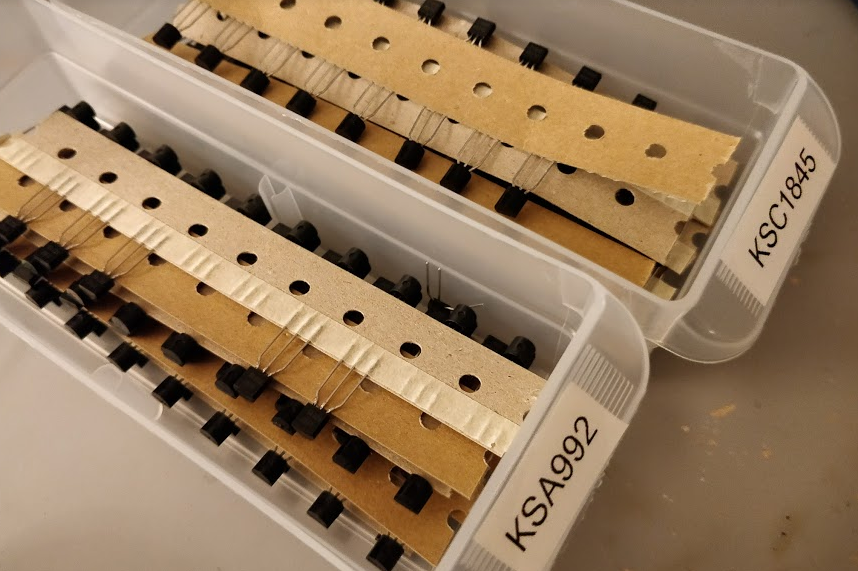
Mouser's finest! I'm not sure about the hfe grade as I can't find the receipt. The package says FCE. FCE is not an hfe grade, but E is the highest and sounds like something I would buy. Shoot me a PM if you'd like.
-
I think I have about 100 of each (ksa992/c1845) that I'll never use if anyone needs. Can check tonight.
-
If you are lucky, it gets a little bit better if you literally reverse the polarity, input to the plate, and take the output off the grid.
-
@cetoole was visiting, so we made a slightly absurd amp using parts from the bin. I had originally milled the chassis with the intention of building a 6E5P triode -> 4P1L triode SE; then realized that would be a bit awkward, since the 6E5P is rated for higher dissipation than the 4P1L. I may have also forgotten that 4P1L filaments need power supplies when I bought my power transformer, too, so that was a non-starter. Not wanting to leave two unused holes in the panel, the obvious solution was to throw some 0C3s in. Glow tubes are pretty; it follows that any amp that uses them will sound better than one that does not. A normal person might be tempted to string them in series and use them as a reference for a regulator. Instead, each channel gets its own shunt regulator with a voltage reference made up of a zener stacked on top of the glow tube, and a SiC shunt device. R7 ensures that the tube strikes. And the current source (which is nothing inspired) The regulator terminates into the cathode rather than ground, keeping the cathode regulator out of the output current loop. It also forces the PNP to run at constant current regardless of cathode current, meaning its impedance will also be constant. It sounds like a single ended triode (i.e. terrible). But it was an awfully fun build. Slightly tempted to parafeed or otherwise upgrade the iron. It's surprisingly silent when nothing is playing.
-
No access to Spice right now but I've had great luck with this circuit and a variation using two PNPs and two DMOSs. If base current starves the zener, use a Darlington or replace the LND150 with a BSS126 or BSP135, I think the reason why the DMOS circuit is so good is that it does not have a bias string that runs parallel to the CCS. The way it's cascoded also holds the lower device's Vce or Vds constant rather than holding Vbc constant, as most PNP cascodes do. Using a BJT as the lower device almost always results in more transconductance, and thus higher impedance.
-
What kind of noise? I've had good luck filtering switchers with a CLC with -3db a decade below fosc (so ~10khz), to pick up where the regulator starts to drop off. Gives values in the low mH and uF range.