cspirou
-
Posts
355 -
Joined
-
Last visited
Content Type
Profiles
Forums
Events
Everything posted by cspirou
-
Interested in GRHV boards. GRLV would be cool too.
-
C has the highest hFe. B might be okay if you measure a bunch and take the highest measuring ones. It seems to be in stock here: https://www.tme.eu/en/details/bc556c-dio/pnp-tht-transistors/diotec-semiconductor/bc556c/?utm_source=octopart.com&utm_medium=cpc&utm_campaign=compare-2018-01 https://www.rocelec.com/part/FAIFSCBC556CBU I haven't ordered from either place so I don't know what they are like.
-
Noticed that 4 x pzta06/56 chips are about same as a DIP-28 chip and I was looking for similar heatsinks. Short of ordering a minimum of 7000 from Mouser, I found these https://console5.com/store/dip28-heat-sink-glue-on-thermal-epoxy-style-dip-28.html So glad there are so many nostalgic gamers out there.
-
The stripe on the Kemet is the + side and should match the solid line on the board. On my board all the capacitors have the stripe going towards the rear of the amp.
-
I used isopropyl alcohol. I had trouble soldering anything connected to the ground plane, especially since its a 3oz board. There was more then a few times that I needed to crank the temp to max to get anything to flow.
-
Is the only thing keeping the GRLV from running effectively <10V the reference? In an earlier post I think Kerry mentioned using a LM4040 and those are available down to 2.048V.
-
Here it is: 10.96 VAC will give you a 5-6V drop before regulation. You should be okay. I suspect you don't want a voltage close to the reference because then you would need a much higher R7/R10 resistor, which would increase noise.
-
Definitely do that. I bought a 18v + 18v transformer and it's giving me 22v + 22v. I'll find the post but I think it's better you use 5v.
-
That would give you ~12V before regulation which is only a 3V drop. Seems to be to cutting a little close. 10VAC is a little more comfortable. also don't forget to change the lt1021 reference
-
unbalanced/balanced to balanced tube input
cspirou replied to kevin gilmore's topic in Do It Yourself
The filaments don't come from a common source, each has their own regulator. This makes sense because filaments require a lot of current. B+ is pretty low current so just one for both channels should be fine. -
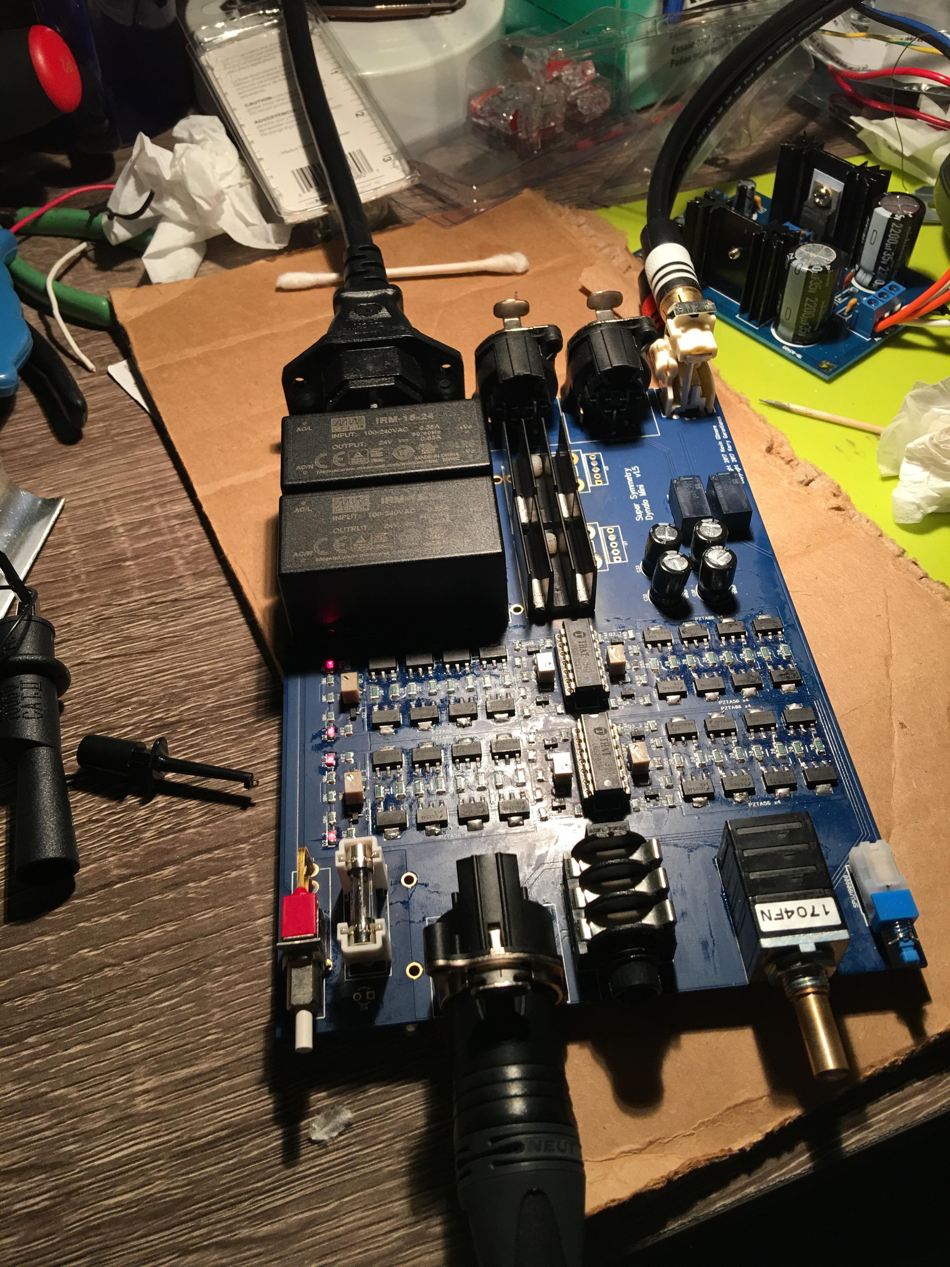
Installed a new negative regulator, adjusted the trimpots and soldered in the 0 ohm resistors. Finally had a listen. I have never heard the full size Dynalo SuSy so I cant compare but this little amp sounds amazing through my HD 6xx! Absolutely no noise except a tiny bit of scratchyness while turning the TKD pot. Voltage rails are +19.99/-20.03. Here are some temps I measured positive regulator heatsink- 50C negative regulator heatsink - 60C output transistors (no heatsink) - 75C Thank you Kerry, Spritzer, KG, Pars, mypasswordis, Sbelyo, John McLean, mwl168, RudeWolf, JoaMat and countless other people for making this possible. Now that I have an amp I am turning my attention to casing. I'm willing to organize a group buy for enclosures but I need at least 10 to make it interesting. Ill make sure to have panels for both the TKD and Alpha pot. Anyone interested?

-
IT WORKS!!!!! All the LEDs light up with power supply set to +18V/-18V. Right channel on the TRS is 70mV and left channel is 190mV. Temperature is a cool 140f without the heatsinks. now we know what happens when you install CCS LEDs backwards.
-
I think I might have isolated the problem. The CCS LEDs appear to be mounted in reverse. For other LEDs the green stripe indicates the cathode but for LTST-C170CKT, it seems to go the other way according to the datasheet. http://www.mouser.com/ds/2/239/liteon_LTST-C170CKT-1175291.pdf With respect to this LED I followed the silk screen and it seems wrong. This is confirmed when I test the LED and put the positive probe on the negative side and it illuminates.
-
unbalanced/balanced to balanced tube input
cspirou replied to kevin gilmore's topic in Do It Yourself
There's one tube per channel. So one set of heaters per tube -
I gifted myself a hot air rework station for Christmas, so not a major issue. In fact I removed the negative regulator and resoldered it because I thought that was the problem along with the 10k feedback resistor. There is in fact one removable component which is the that340 chips. Would there be any issue running the amp without those chips? The top side was all hand soldered along with the through-hole components so I suspect the issue is the bottom because I was a little too generous with the solder paste.
-
After a hiccup where a capacitor exploded on me because I installed it backwards, i finally have a functioning lm317/lm337 power supply. I adjusted it to +20/-20v with 10k resistors as loads and then hooked it up to the Dynalo mini through the offboard regulator holes, bypassing the onboard regulators. After powering it on the rails dropped to +15v/-15v. At the TRS jack the voltage was about 0.4v instead of the 9v I measured before, but the output transistors were 220f! I also noticed the CCS LEDs weren't lightning up. i didn't want to check other voltages while its running so hot. So ill turn it down to +9v/-9v before i start investigating further.
-
Nice to know that the ubal/bal boards are good DAC output buffers.
-
Are pins 1 & 5 for higher current capacity?
-
Should be the same OP27 used in the Dynalo
-
I thought they were the same but just used a different code?
-
Just curiosity as to how universal the GRLV is. Interested.
-
According to the datasheet for the MJW21194, they are rated up to 16A. I wonder how far the GRLV can be pushed. Could it power a First Watt F5?
-
I have an lm317/lm337 bipolar supply I could use but it's not assembled. Just trying to see if I could get away with the single supply I have, but I'll just build it anyway.
-
Here is what I get with an ohmmeter so far Left vs right TRS - 79.6kohm L/R TRS vs GND - 26.4kohm +V vs -V rail - 4.67kohm +V vs GND - 33.33 kohm (starts at 22Mohm) -V vs GND - 5.835 kohm (30kohm when I reverse leads) There was a couple resistors near the opamps that i fixed but didn't seem like an issue i have a power supply i can connect to the holes for the offboard regulators. Is there any issue bypassing the meanwell and TSP7A and using my own supply for testing? Also could I just run the negative rail or do i need to run both rails?
-
Finished soldering my Dynalo Mini but I have problems. First thing when I switched it on the CCS LEDs did not illuminate. Checked voltage at the TRS jack and it was about 8-9VDC. The Meanwells work fine and show +24V/-24V. The positive regulator is still showing +20.00V but the negative regulator is now showing +1.76V. This is very frustrating since it was measuring -20.02V before I started soldering the amp components. Do I assume that the negative regulator is fried?