cspirou
-
Posts
355 -
Joined
-
Last visited
Content Type
Profiles
Forums
Events
Everything posted by cspirou
-
Very nice @Kerry! That pinout looks compatible with the Dynalo Mini board.
-
I assume the feedback resistors will be left off so we can set our own voltage? Or could we request different voltages?
-
Interested as well. Also fine with unpopulated PCBs
-
Where would be a good place to get boards assembled?
-
With 24vac you are getting 33Vdc before regulation. Thats a 13v drop and far more then you need. The problem though is for a given VA rating the current capacity goes down as the voltage goes up. You probably sourced too much current and burned out the windings. get 2 x 18v instead
-
True, not to mention that it's not even up to it's running temp.
-
Thanks! Although I think its more likely the 10k feedback resistor is off by 5 ohms. Also I did a shitty job soldering that particular resistor. Redoing it might give me a better result. Or not.
-
Success! After a few days of dealing with the regulators I finally got them soldered in properly. +V: 20.00V, -V: -20.02V of course the 0.02V offset is super annoying even if it is within 0.1%. I calculated that I would need to add a 23.8 Mohm resistor in the AOT spot to adjust the voltage to -20.00V. Not really worth it, although I might just add it to my next Mouser order.
-
Thats only for the positive regulator. The negative regulator uses a feedback resistor to determine the voltage.
-
Okay, I think I fixed it. I wont know for sure until I test it later tonight. Just one question. The pins on the bottom of the negative regulator are bridged and I was having a hard time removing the excess solder. Then I noticed that all those pins were connected to the ground plane anyway. Does it matter if they are bridged?
-
and now for something completely different part 3
cspirou replied to kevin gilmore's topic in Do It Yourself
My brother got free next day shipping on his very first Mouser order. He also lives in Houston and Mouser is based in Dallas so I dont know if that had anything to do with it. -
Believe me, I learned my lesson. If I attempt soldering this sort of chip again I'm using a stencil. I found them for $10. http://www.kr4.us/QFN-20-0.65-mm-pitch-5-x-5-mm-body-3.1-x-3.1-mm-pad-Stainless-Steel-Stencil.html Has anyone been successful applying the iron directly to the heatpad like in this video?
-
The soldering iron I use has dual irons (one fine, one chisel) so removing the capacitors isnt so bad. I assumed I couldn't feed solder because the pins are under the chip but I'll try it out.
-
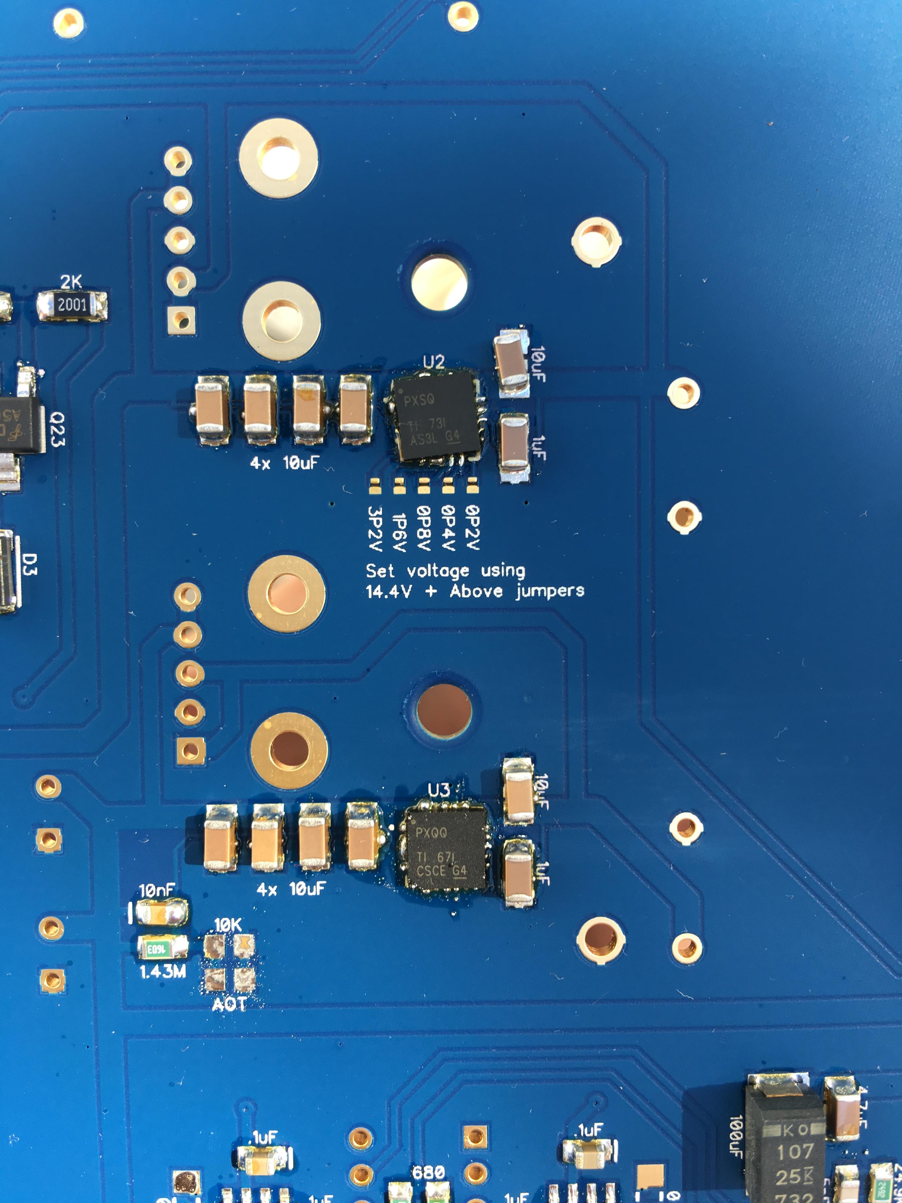
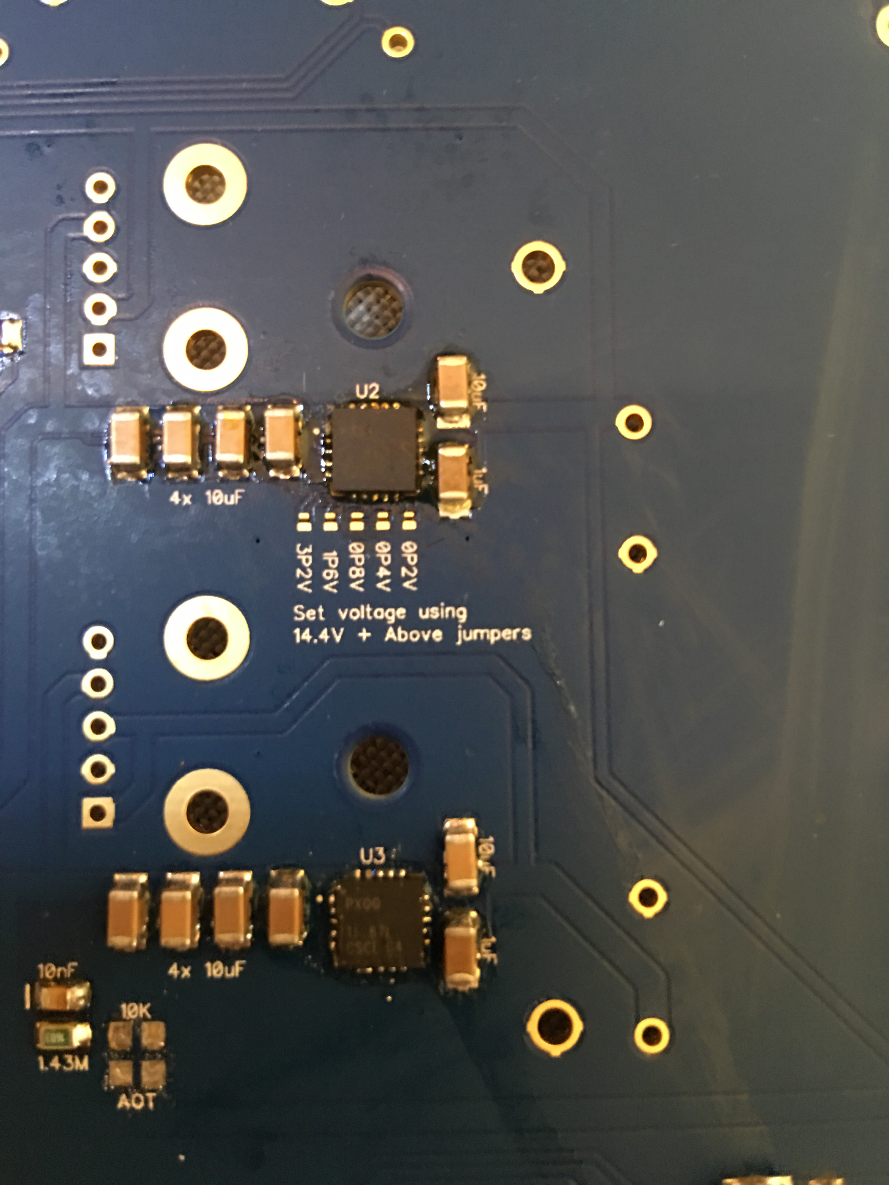
So ive been using a toaster oven for reflow. I did a test and the result were promising. I was a little too confident and soldered the QFN chips for the Dynalo mini. First time I used a little too much paste and ended up with something like this. the positive regulator is out of alignment and the negative regulator has the bridges. I decided to reflow a second time and nudge the chip into place. Now it looks like this. i thought my problems were solved but when i powered up the positive regulator I only meaured a voltage of 7.87 V instead of the expected 14.4V. This means that only one of the 6.4V pins soldered. Very frustrating. So what I am wondering is how many times can you reflow a board before the components are affected? Should I remove the capacitors first? I would prefer to use a hot air station but I dont have one.

-
Thanks @luvdunhill! I'm using the buffer with the ubal/bal board which have a 1.3kohm resistor to ground on the output so i don't think an additional resistor is necessary. Plus I already have the PCBs and the pins match. I am interested in buffers for another project though. Ill let you know.
-
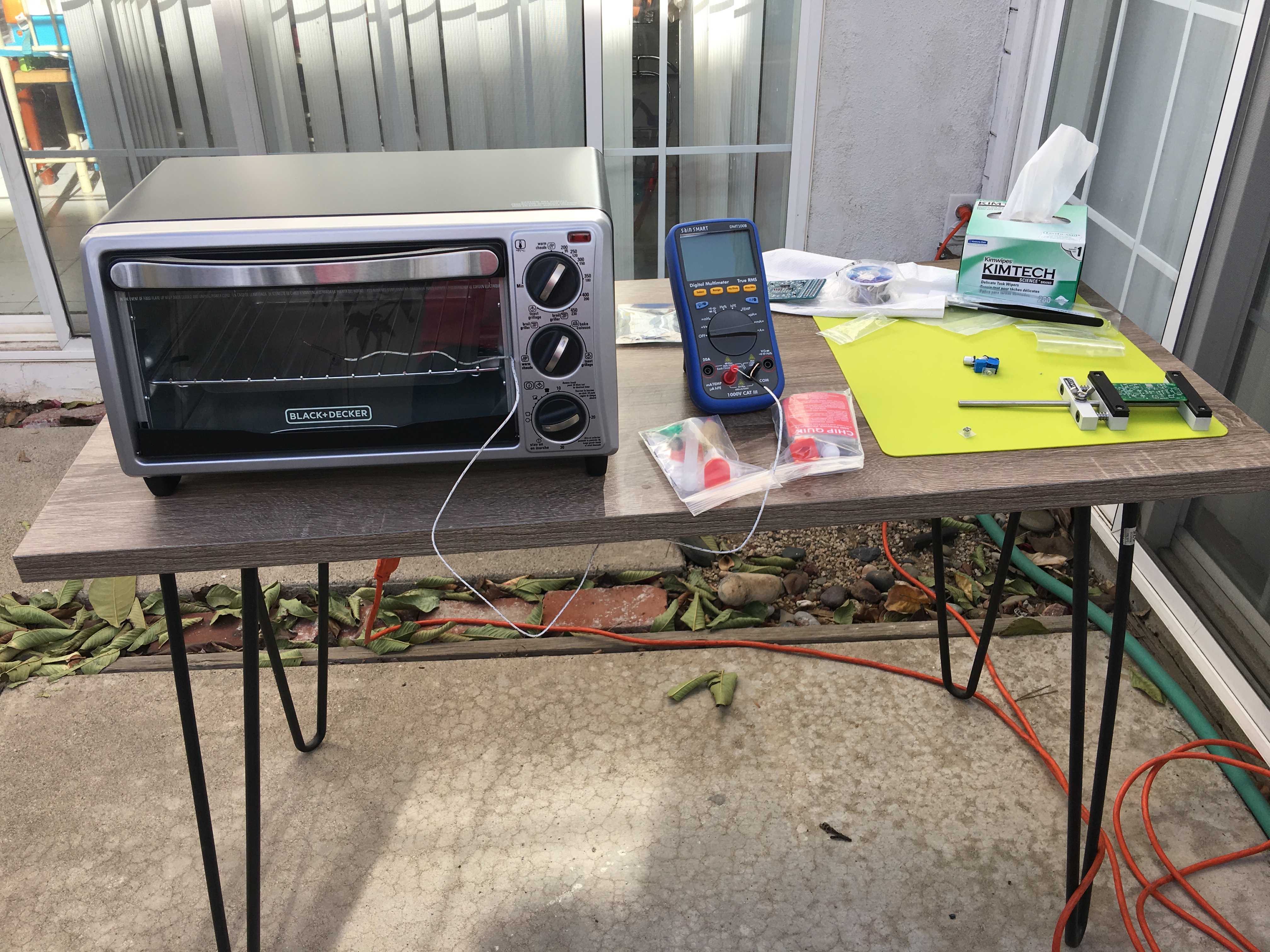
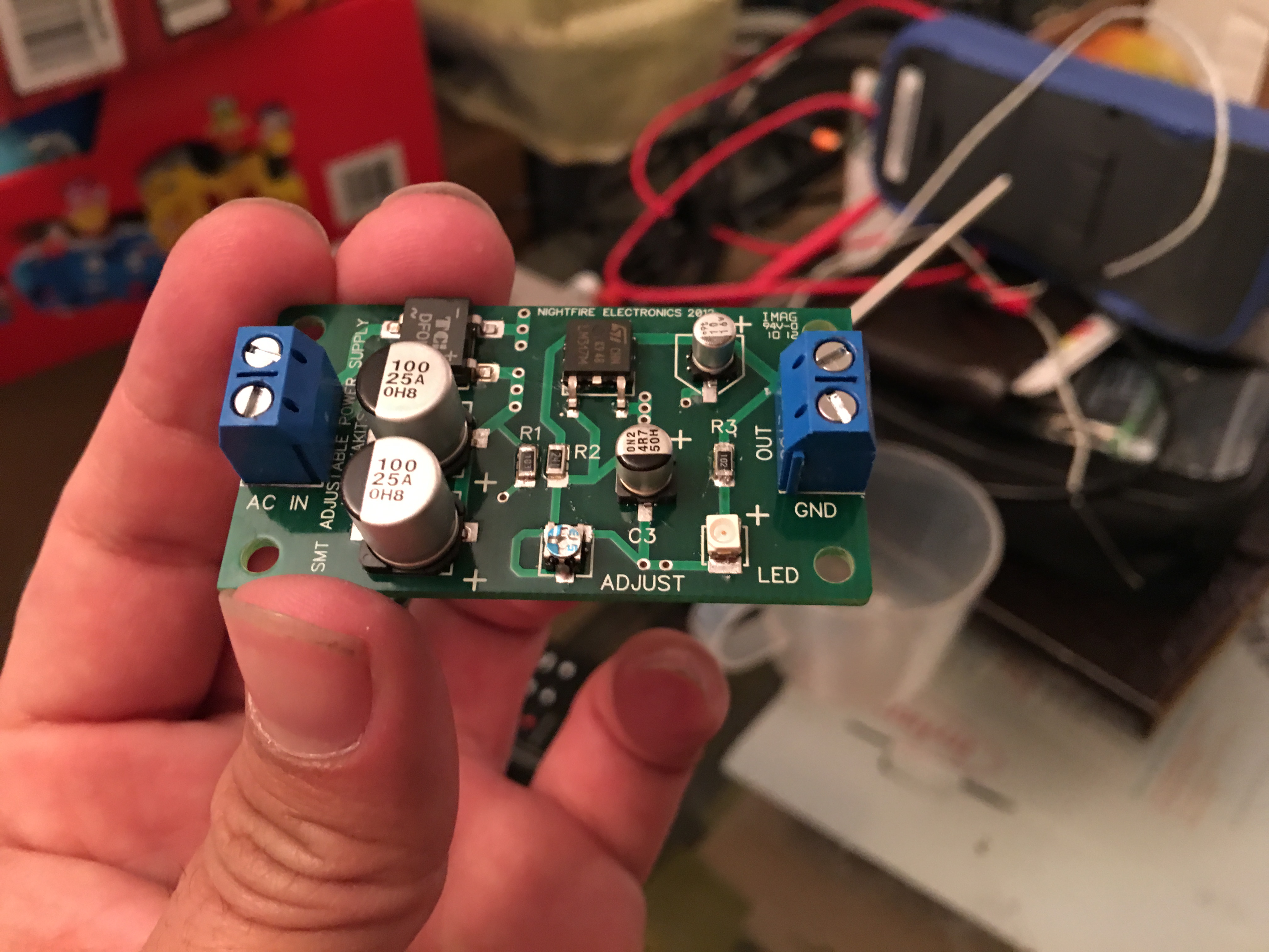
So I thought I would try out reflow oven soldering with a toaster oven. The AMB regulators for the Dynalo Mini are $40 whereas the toaster oven was practically free. I figured trying to solder with the toaster would be worth a try. It would also help with all the other SMD projects I have. I don't have a controller for now so I did it manually. As a test I bought an SMT adjustable power supply kit from Nightfire electronics. I had a little too much solder for the LM317 and one resistor didn't self-center but I'm pretty satisfied with the result. I'm thinking about using this for the R2R attenuator board. Anyone know what the procedure is for doing reflow on 2 sided boards?
-
When matching transistors do you only need to match complimentary pairs? Or do all the transistors on one channel need to be the same?
-
Damn, i wish I knew chinese. I see you made the TKD version @astro, would you mind posting the front panel layout?
-
There's a fuse near the switch. Nice work @astro! Where did you do your casing? Are those temperatures inside the enclosure? Are there holes underneath?
-
They should be able too. All these transistor testers are based on some open source project https://hackaday.com/2015/04/24/review-transistor-tester/
-
I drew a schematic of the diamond buffer in case anyone needs it KG-Diamond-Buffer.pdf
-
Verical has 2sc3324-GR but not 2sc3324-BL. KG mentioned that the highest hfe should be used which is the BL version.
-
Digikey says that 2SC3324/2SA1312 is NRND and is recommending 2SC2713/2SA1163 as a substitute. Any reason why I wouldn't be able to use the 2SC2713/2SA1163 transistors for the unbalanced/balanced board and diamond buffer? Comparing the datasheets for 2SC3324 and 2SC2713 it seems like the 2SC3324 has a lower noise figure, but otherwise have identical specs. 0.2dB and 1dB max vs 1dB vs 10dB max respectively. Seems like I should go for the original pair while I still can. Too bad it's backordered on Mouser until March.
-
I got lucky and was able to make a small order. Minimum order is 1000 pieces. If there was a group buy with a minimum of 20 each we might be able to reach that. A lot of people bought multiple pots so maybe someone is kind enough to sell one to you. otherwise it’s probably better to do the version with the TKD pot, which you can order direct. Or air wire an ALPS pot like someone else here did.
-
Another edit to your BOM. The transistors should be the BL type, not the GR. So the 2SC3324 transistor should have mouser part 757-2SC3324BLTE85LF