simmconn
Returning Member
-
Joined
-
Last visited
Everything posted by simmconn
-
-
I’m surprised to see the series pot only gets 16dB CMRR at min position. The attenuation at that position would have been much higher than 16dB already, for both common mode and differential mode signals. Did you use the same schematic in your earlier post to connect the series pot when using the APx CMRR measurement? I think the source XLR pin1 should be connected to input XLR pin 1, and series pots’ pin 1,3 should be between the source XLR pin 1 and 2/3 respectively, like how you would connect in a real system.
-
I think you are not measuring CMRR, but rather the common mode to differential mode conversion ratio. With the ‘conventional’ dual pot connection, the common mode signal at the input is attenuated at the same ratio as the differential signal; while with the shunt connection (without the help of a line isolation transformer), the common mode signal is not attenuated at all. Apx has common mode drive, why not use it to evaluate CMRR?
-
I like the idea with the 211. It also helps keeping the noise from the filament supply at bay with the common cathode configuration. If matching tubes for the CCS sounds too much, we can always consider the 1700V depletion mode SiC JFET. Thermal management is going to be a challenge though at 35ma.
-
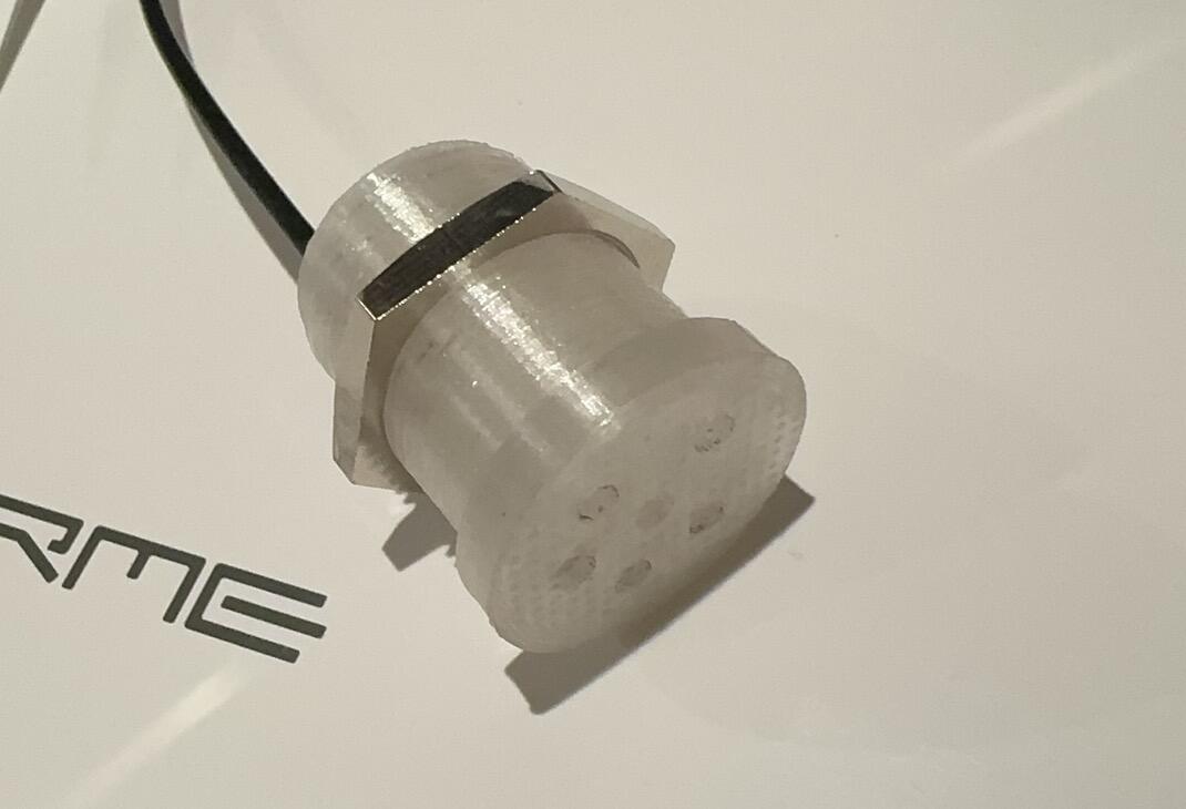
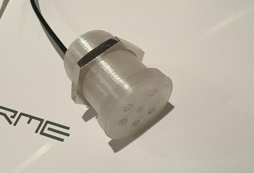
Nice two-piece design! Actually TE and Molex both have 0.093” (2.36mm) crimp contacts in their portfolio. One can make real cheap Stax sockets using those and a 3-D printed shell. The contacts are so cheap that I think not being able to extract them after assembly would be okay. The gold-plated varieties are more expensive, but I’d feel less guilty than cannibalizing Neutrik jacks. Below is one of the one-piece shells I printed using PETG. However I was not quite happy with the surface finish of the 3-D printed shells. Machined shells using acetal and PEI both give nice surface finishes and are plenty rigid. Perhaps too rigid that the RR1 plug starts to show fitting difficulties. 😅

-
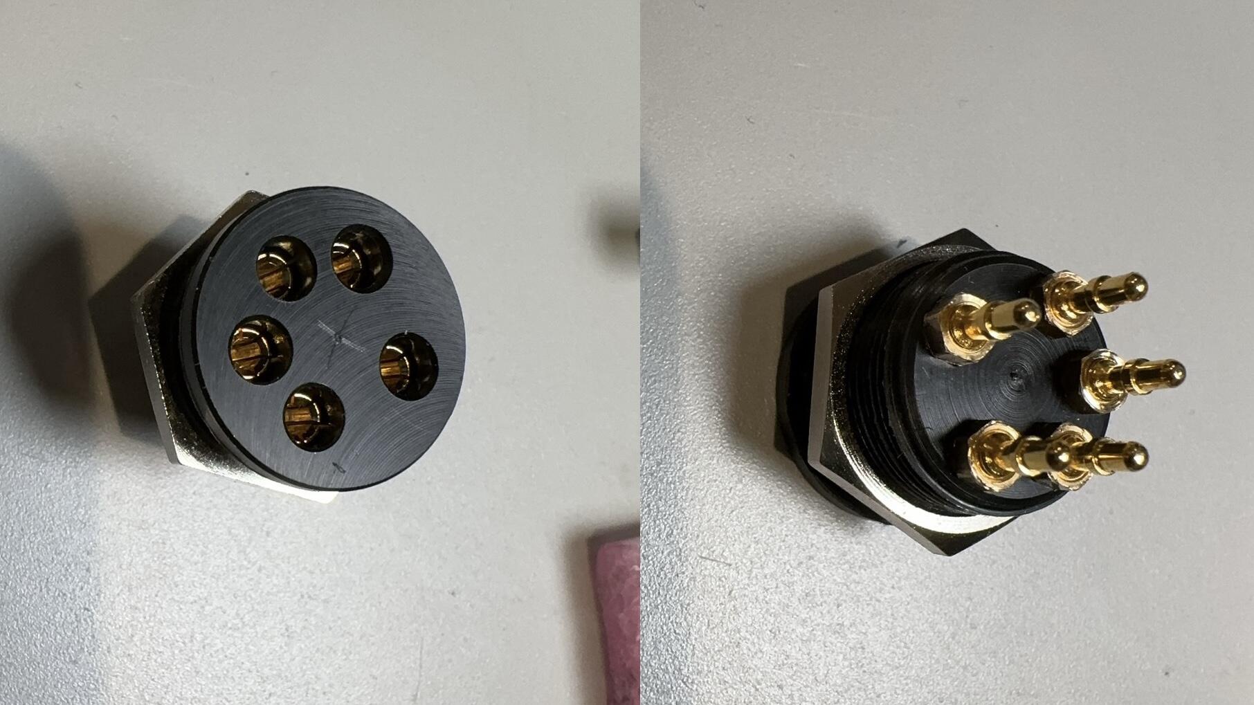
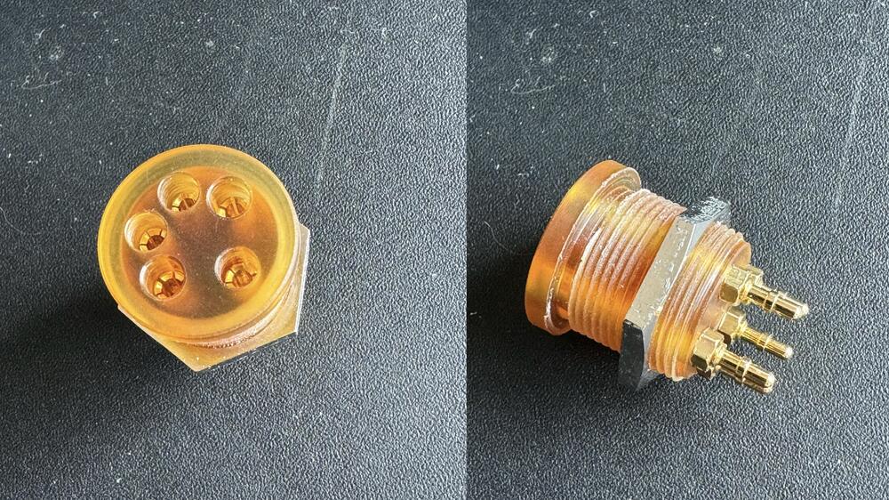
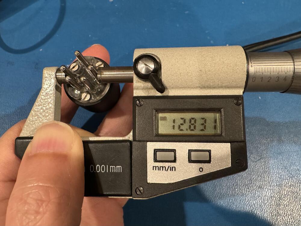
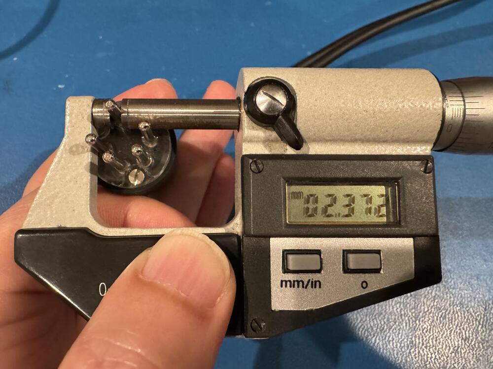
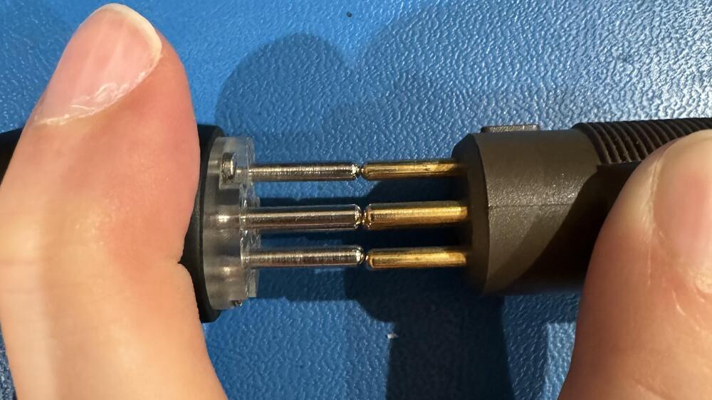
I posted the pictures to show how I derived the 10.459mm pin center-to-center dimension. The center-to-center distance is critical in designing the plug or socket, because it is independent from the tolerance of the individual pin diameter. 0.4mm error is quite a bit when put in perspective with regard to the nominal dimension. Your own measurement also shows that the pin distance of the RR1 plug is smaller than the Stax plug. If I were you, I'd go back to the drawing board and find out if the target dimension was incorrect to begin with, or wasn't well controlled in production, rather than sweeping the dust under the rug with 'no disruption in functionality'. A smaller plug can force into the socket thanks to the flexibility of the socket contact and/or the plastic shell. If the socket is made of hard material (such as G10 or phenolic resin) and the contacts are held to high tolerance, a smaller plug would have a hard time fully plugged in. There hasn't been a wide-spread problem because most of the sockets either use soft material (such as Teflon) or contacts that are not held to high tolerance (such as the tuning fork style contact used in the Stax sockets). I'm not saying that every RR1 plug has as large tolerance as mine. But if not, you may have a product consistency issue. Maybe hand-soldering the pins on an acrylic retainer (melting point 160°C) wasn't a good idea after all. "ensure everything is built with precision from the start", "adhering to the strict Production and QC directives". Those are easier said than done.
-
Maybe I’ve got an outlier, but the specimen I have measures only 10.459mm between L- and R+, center-to-center. The distance between L+ and R-/BIAS has similar error that I can visually see it when placed head-to-head with a Stax plug. Without tapping into the proprietary design data of your plug, could you tell us how the Stax plug measures on your end?
-
Anything new about the 5-pin plug? I hope the pin pitch is fixed this time.
-
It’s likely that large amount of AC could mess up with DC measurements. The T2 amp stability is a bit tricky. If my simulation is correct, its loop gain 0dB crossing happens with a -40dB/Dec which is unusual. Taking out the 5pf would most likely cause the amp to oscillate. The question is whether your amp is/was oscillating with them in place. An oscilloscope would be needed to make sure of that. With a scope you can also trace back and see where the oscillation originated. Well, the last T2 builder whom I criticized for not having proper equipment shied away, so I’ll refrain from saying anything further. Also in my simulation the C1/R5/R92 compensation network doesn’t have much effect to the stability since their corner frequency is quite low. Even lower is the corner frequency of the balance servo. So they probably don’t have as much effect as the battery voltage. It may have just happened to me that the unit I worked on has 740V well in the middle of the ‘stable zone’. You could test the CCS as individual blocks. Remove the EL34 and connect the anode pin to ground at the socket, then you can test the CCS at equivalent to idle condition. If you’re less confident about your CCS, connect output+ instead of o+ to ground and the 5.1k output resistor will offer some protection. The 5pf cap and the 100k resistor form a zero at about 318kHz. If you increase the cap slightly it may give you a bit more phase margin. But if everyone else’s amp work fine with 5pf, you should not need more.
-
To get the balance servo out of the way I would disconnect R84 and R85 from the opamps and then tie their loose ends to ground. This mimics both opamps' outputs at the center level. Disconnecting R88 and R90 alone may not be ideal because the opamps have input offset voltage and can still integrate against it over time. However, if you measure near zero at the opamp outputs you can leave it as is and not worry about R84 and R85. Check to see if the J79 is shot or fake. That enhancement mode PMOS FET takes about -0.45V Vgs to conduct 10mA. Note that the mu of EL34 in triode connection is about 10. So under the same plate current, 5-6V of Vg difference would cause 50-60V difference on the plate. Do you measure and match the parts before putting them in the amp? The voltage drop on the LED depends on the current and part-to-part variations. I see some people like to push them all the way down on the PCB. Not only you can't measure the voltage drop easily on the component side, but it's also bad due to thermal stress. I remember when I first used LEDs they were pretty fragile, soldering needs to happen at least 5mm from the body with tweezers to help dissipate the heat. D7 and D8 are in very different locations. You probably mistake one for another. True. The balance between O+/O- can affect the CCS a little bit but not enough to throw the LED off that much. Your starting point is that V(R17)=V(R27). Going down the chain, the cause for D10/D11 (I assume you meant those) to drop less than their counter parts are: 0) poor LEDs, 1) Q11 or Q12 stole too much current (easy to verify by measuring across R21 thru R26) , or 2) Q13 thru Q15 have low Hfe (harder to verify but unlikely). There are two feedback paths that maintain the battery negative voltage, the front-end servo and the global NFB. For the front-end servo, Q26 & Q27 Vg↑ → Q34 Vb↑ → I(R9 & R10)↑ → U1 Vk↓ → U1 Va↓ → U2 Va↓ → Q4 & Q5 Vs↓ → Q26 & Q27 Vg↓ For the global NFB, Q26 & Q27 Vg↑ → Q26 & Q27 Vd↓ → U3 & U4 Vk ↓ → U3 & U4 Va ↓ → U1 Vk↓ (see above for the rest of the loop) It looks like there are multiple problems. So bad parts or questionable PCB connectivity?
-
I did not say dB/V and dB/mW are the same spec. I said specifically 101dB/V at 8 Ohms is the same as 80dB/mW. If you know why dB/V at 1000 Ohm is the same as dB/mW, you'll understand the math behind my statement.
-
I’m not sure what point you try to make. Isn’t 101dB/V at 8 Ohms equivalent to 80dB/mW? How can the same spec on one hand ‘low efficiency’ and at the same time ‘high sensitivity’?
-
@jokerman777 I use a 10K trimmer in place of R73 for a forum member's DIY T2 as well, to trim the ~10V offset down to near zero. I know the transistors are most likely not matched on that unit and it doesn't make sense to remove them and match again. In your case the offset is significantly more. I would try to root cause it before replacing R73 with a trimmer. FYI the Vbe of Q33 and Q32 measured on that unit are 0.5xV and 0.6xV respectively. It's definitely a problem if Vbe measures negative. To troubleshoot point C and D, you can temporarily disconnect the 2.2M resistors R80 thru R83. Measuring across R89/91 with a meter having 10M Ohm input impedance only adds about 1% error, so no worries. Check the polarities and short on D29 thru D32. They could pull the voltage at C/D through R80 thru R83 if in a wrong polarity. Once the voltage on C/D correctly reflects O+/O-, the balance servo can still bottom out trying to adjust. Measure the output voltage of the opamps. If they come within 3V of its power rails, I'd trim the battery voltage gently so the opamps come back to the 'comfort zone'.
-
@jokerman777 I'm not sure what problem you have with the battery now, especially with the working channel. Can you still reproduce the problem in your post? It's normal to see both top and bottom voltage changes as your battery voltage 'contracts' or 'relaxes', since multiple feedback loops are in action trying to compensate the changes. I'm not too worried about Hfe of Q23. You probably already did the math. At 740V battery voltage, the current through Q23 is about 3.23mA. Since R39 passes about 0.1mA, Hfe of Q23 should be at least ~33 in order not to starve the Q16/19/20 branch even in the extreme situation. The original design seems so marginal, since the 2SC3675 is spec'd for Hfe>30. The good thing is that in reality, the C3675 has a quite slanted output curves unlike the datasheet suggests. Its effective DC gain increases as Vce increases. One of my samples measured at Hfe=38 with Ib=10uA at low voltage on a tester only needs about Ib=40uA to get Ic=3.2mA at Vce=740V. Essentially you get doubled Hfe in the real circuit compared to on a transistor tester. Sorry my CRT curve tracer has a broken flood gun so I can't show you the complete picture. Ib=40uA is still a large chunk of the 100uA from R39, which seems to be different from one would think, that the load current is usually a small fraction of the DC operating current of either arm in a diff amp. I think your way of reducing R39 is in a right direction. If I were to take a wild guess, the R39 could have been 6.2k (Blue-Red-black-Brown) instead of 62k (Blue-Red-black-Red) in the original T2 design. You see that besides the tiny decimal point, the color coding is also very close to each other. It's not uncommon that such mix-up could happen in any stage of manufacturing, and copying. With R39=6.2k it'll make the A1486s operate at a comfortable 500uA each and still within 200mW which is okay without a heat sink. I would expect the adjustment to be less finicky now that the main amp has a lot more juice and the output device has 30% less load. More importantly, some of my genuine C3675 show onset of breakdown at Ic=3.2mA, Vce=740V. Getting the current down would also help on that. By the way the A1486s has excellent low current linearity that's probably why the battery had worked at all under such a low current. Regarding the battery current, the R62/63/74 also drain some current so it needs to be added to what you measured on R58/59. Let's get your math straightened out. From -561V to -541V it is going UP and not down, this is important especially when most of the circuit is referenced to B- (-560V). For the Q32 and Q33 in the channel with large offset, have you measured their Vbe separately, and compare with the good channel? I hate to repeat myself, but you've got to measure all nodes. When something isn't working, every component and every connection is a suspect until proven otherwise.
-
If you use a thick PCB, be aware that the through hole pads can fail during component removal (disconnection between the annular ring and the hole barrel or inside the barrel) that is difficult to detect. A simple workaround is to always solder both sides of the through hole pad after replacing a component. 'De-rating' may not be what you think it is. De-rating means reduction of a rating based on certain operating conditions. For example, the LTL4213 LED has max If of 15mA at TA=25C, "Derating Linearly From 50℃ at 0.2mA/C" means at 60C, the max If de-rates to 15-(60-50)*0.2=13mA. You are operating the LED at way below its max If, de-rating doesn't apply here. What you worried about is perhaps degradation, that the If/Vf relationship changes after long-term exposure to high temperature. We've discussed it somewhere in this forum. If I remember correctly Vf increases for the same If due to degradation and not the other way around. Yes D2 and D3 are for protection purpose only. Previously both the LED string and the K246 are suspicious based on your voltage measurement. Fixing either of them would make the battery work more stably, but not completely right until you fix both of them.
-
Voltage across R73 and R64 should differ by 2x Vbe and not the same. That probably indicates that your output offset servo Q33/Q32 isn’t working properly. If you measure any Vgs at more than 1.5V, chances are that the MOSFET is fake. Not a big deal since they are used as source followers except Q26/27 where linearity matters. R99 and R100 are isolation resistors meant to reduce the effect of parasitics when you measure the battery with a multimeter. They don’t carry any current.
-
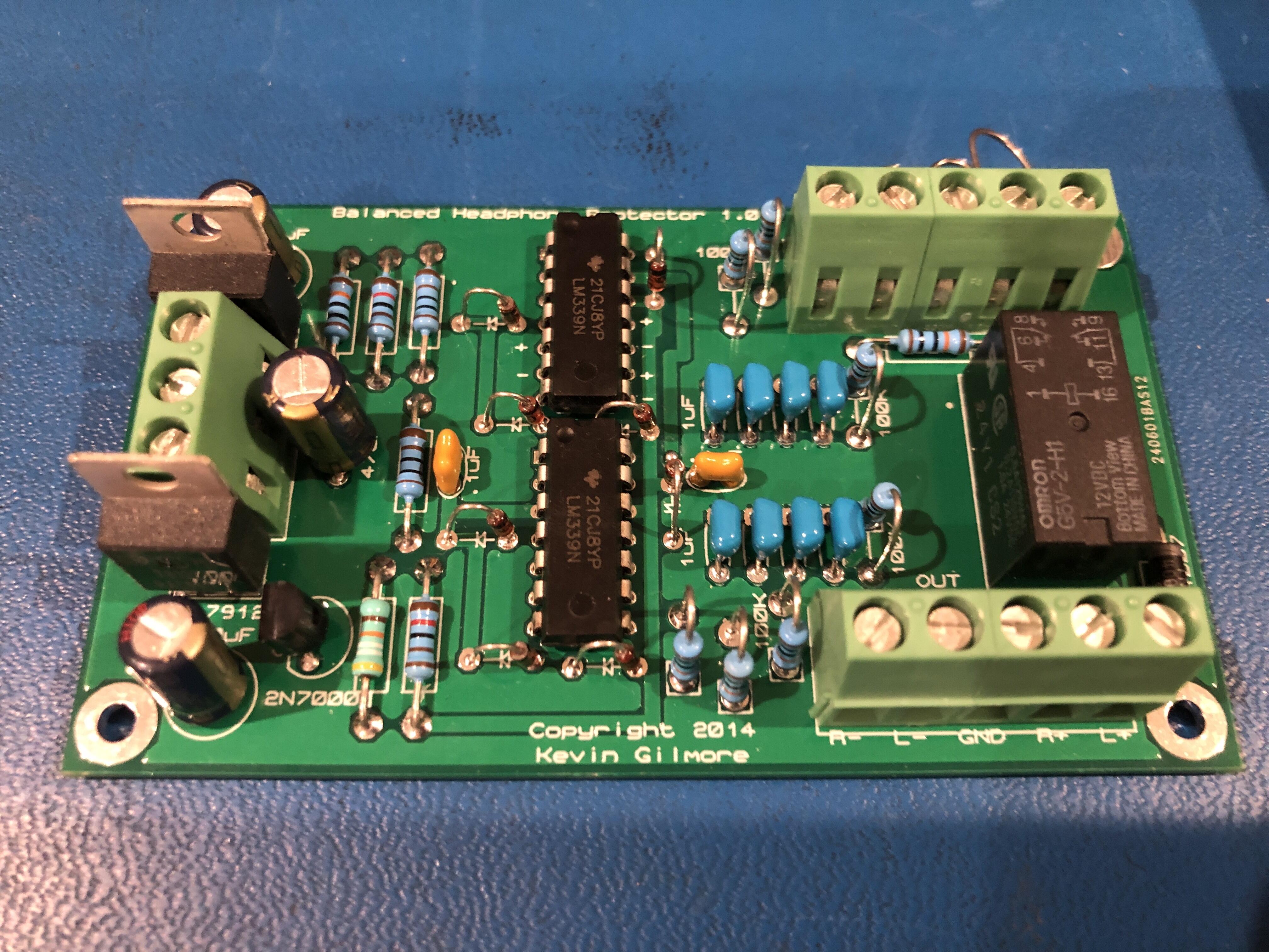
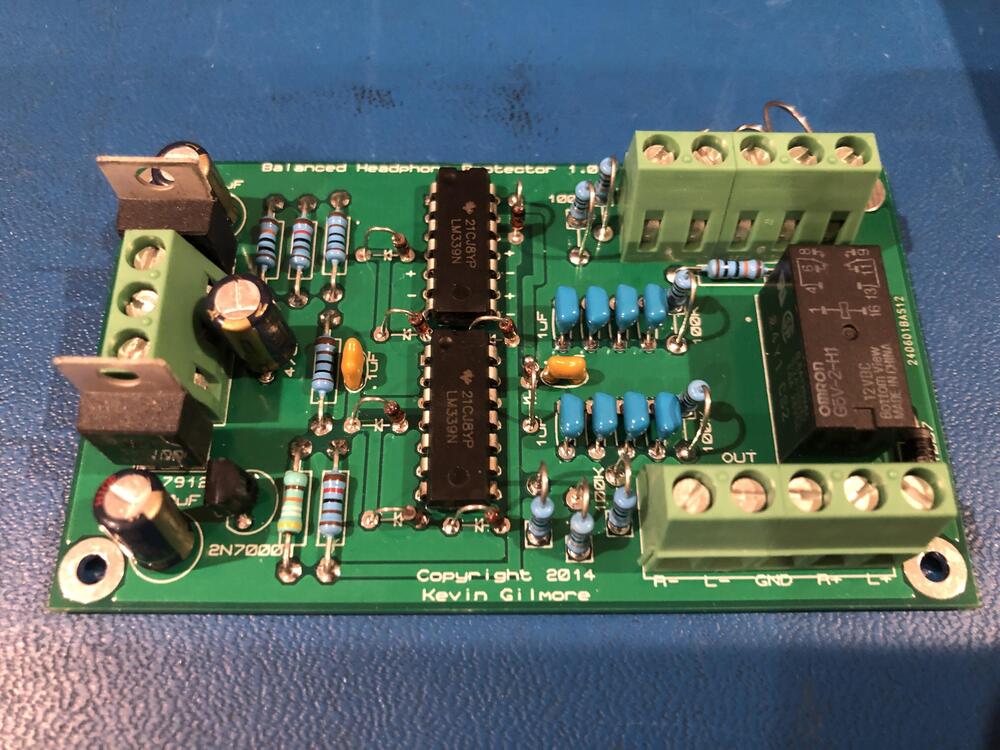
I bought this finished protector board on Taobao for about $12. The parts look reasonably good. It could use better cleaning off the flux residue on the bottom side. Totally worth the time I would otherwise have to spend soldering it.
-
-
What about the A1943/C5200 or A1302/C3281 variants? They are more linear in the medium current range (1A to 5A) than the 21193/94 but are also faster.
-
Congratulations! I can’t say that I fully agree with your analysis, but I guess getting the amp working is what matters.
-
LED: The numbers are all over the place: Your IV curve shows the LTL4213 should have Vf between 1.725V and 1.750V with 0.5mA of current. You've got three different voltage ranges for the LED. Which one is correct? You need to find out where the dependencies come from. Your previous LED chain voltage measurement shows 12.1-10.7=1.4V of voltage variations with not much If change. Is the 1.4V evenly distributed across 7 LEDs? If you suspect Vf change due to the temperature coefficient, that's easy to verify. Just keep monitoring the LED voltage with the amp powered on from cold. 2SK246: Your test indicates that the 'backup ones from ebay' are probably good. Unless the ones on the board are from the same seller and same batch, the test result probably doesn't help much more than that. Rather than replacing parts shotgun style. I'd take voltage measurements shotgun style, then sit down and analyze the data. Replacing parts without knowing why and what would be a very inefficient way of troubleshooting. For example, when looking into the active battery, measure voltage on all nodes. Beware of the burden by the DMM input impedance (usually 10M Ohms but YMMV), so plan carefully when you measure across high-value resistors. When looking into the final stage, collect enough voltage data within the CCS so you can calculate the current supplied by the CCS. Measure the voltage at Output+/Output-, then determine if the tubes are in the right operating point. If you know very well how the circuit works, you can strategically take only a few measurement at key spots; otherwise just do more leg work and collect all data. Don't worry if some could be redundant. They often end up helping you where least expected.
-
You can’t control the ganged mechanical contacts to open or close at the exact same moment. So technically when two or more contacts are connected in parallel, the interrupting current rating won’t double. However, paralleling the contacts does reduce the contact resistance, if that’s your goal.
-
Yes the 2SK246 looks suspicious. Its |Yfs| should be around 1mS around Id=300uA, so changes in Vgs of 1.51V-1.43V=80mV should generate 80uA of change in Id. Apparently that's not the case here. You could use a 2SK373 or even a 2SK117 as a substitute. The 2SK208 is also a close sub, albeit in SOT-23 package. Also, Q16 Ib should not be that high. The current thru R39 is about 100uA, split between Q16 and Q17. If Q16 has an hFE >100, it's Ib should not be over 1uA even in the extreme case.
-
It looks like most of the voltage adjustment comes from the wandering reference, no wonder you said RV1 doesn't have much effect. Assuming your Q16 path works okay, comparing the two diagrams, V(R42) dropped (6.22-6.56)/6.56=-5.18%, almost the same as the LED string voltage drop (11.4-12)/12=-5%, which means the 2SK246 ccs didn't have much effect at all. To give you a data point, my mocked-up 2SK246 ccs changes V(22k) from 6.5496V to 6.5446V (less than -0.1%) when the supply changes from 12V to 11.4V. Your LED string seems not great, either. When the current drops from 703uA to 663uA (-5.7%, ignoring the Q16 base current), the LED string voltage drops -5% as well. Not much of regulation, isn't it? I grabbed a random red LED from my stash and in similar situations its forward voltage changes from 1.7914V to 1.7881V, only -0.18%. Your LED probably has 700uA right around the knee on its IV curve. It may not be a bad part, just not suitable for this location. The above assumes the Q16 and the rest of the battery circuit works okay. Oh well, let's fix one problem at a time.
-
The difficulty setting the V(R42) to 6.55V could be due to something else. I assume that you observed different pin out when substituting 2SA1486 with 2SA1413. As long as the LED strings are lit stably and not flickering, the RV2 should adjust smoothly for 6.55V across R42. The idea is to set the 2SK246 ccs to about 297uA with the majority of that going through R42 and only a tiny bit from the base of Q16. If you have some spare 2SK246 from the same batch, resistors and pot, breadboard a circuit and test with a bench DC power supply. See if the pot hits the bottom or something wrong with your 2SK246. It’s a good idea to measure around the active battery circuit, using the top node as the reference point, mark voltages and currents on the schematic. The active battery does not take rocket science to troubleshoot. You just need to know 1) Ohm’s law, 2) Transistors have hfe, and 3) A forward-biased silicon junction has a voltage drop about 0.6V. There is no need to be paranoid about the battery not being spot-on at 740V. Since it is transparent to the audio signal, they can even be purposely set slightly differently from each other to compensate unbalances elsewhere in the circuit. But if your amp don’t like them being near 740V at all, that means some other parts of the amp is quite different from what the designer has envisioned. There are quite a few feedback loops in the works that maintain a near-zero offset. Let go of the active battery voltage temporarily in exchange for zero offset can set those loops at their normal operating point and help you find out who’s not behaving correctly. Mark any voltage reading with a ‘*’ if you hear oscillation when you get the reading, as it may not be reliable.