


simmconn
Returning Member
-
Joined
-
Last visited
Everything posted by simmconn
-
Is it the 'ok bias' channel in your schematic that has large output offset with servo disabled? I gave my analysis in my post. Q24 and Q25 form a current mirror. The current through R21 should be the same as the current thru R31 and thru the R26. Apparently it's not the case based on your measurement. I would focus on the related few components.
-
The protector board needs a solid ground, i.e. split +/-15V power with their common GND tied to the amp GND. A single floating 30V would not work, because the 12V relay only draws power from the +12V and will throw the GND off center and causes feedback to the comparators. You can share the +/-30v with the amp. Make sure the variety of 7812/7912 you use are rated for 35V or more, and the 7812 has sufficient heat sink for continued operation of the relay.
-
@SatyrnineWhat does it mean by the minus sign on the voltages? It wouldn’t make sense unless you mark which pin had the red probe on it and which one had the black one. You might instead mark the actual polarities, like the pin with higher voltage with a (+). For voltage to ground such as the servo output, it should be the actual voltage. You marked -10V on the schematic but said 10V in the post, which one is true? Based on the voltage drops on R19/R21, it should be 10V, so the lower current mirror should have more current than the upper one. But that’s not the case when you compare the voltage drops across R25 and R31. So something must be off there. The transistors seem very mismatched. Btw, most of the reference designators are hardly legible on your hand-marked schematic. If you expect people to help you, at least make it easy for them to do so.
-
You are welcome. It depends on how quickly they drift. My understanding is that the largest part of the drift is caused by the transistor parameters’ temperature effect. That also includes the Hfe of Q32 Q33. Unlike the balance servo, the offset servo is a proportional regulator so its error varies with the gain. Hence the offset varies with temperature. If it drifts up and down faster than like one hertz, it gets into the 1/f noise territory and needs attention.
-
That’s a good point. My understanding is that imbalance always exists in the circuit, and it’s meaningful to see if the imbalance is small enough for the servo to compensate. So it’s probably still useful to have the servo in the loop when troubleshooting, rather than trying to balance the circuit manually and then engage the servo. The servo opamp output is an indicator of the imbalance. I’d adjust the +/- active batteries in the opposite directions after warming up, such that the servo opamp outputs are well within the +/- power rails.
-
Good to know that the R ch works okay now. How high a voltage is too high on C/D? If it’s like the L ch before (about 1V). It’s normal for T2. If you want absolute zero offset, I have a solution in my post last Friday here.
-
I’m not sure if you used the “original” DIY T2 enclosure. The transistor mounting hardware are difficult to access in the recessed space and easy to get lost. I would do sufficient measurements to narrow down to a suspect before removing anything. Like you’ve found out, it’s not always the transistors that go bad. If I were you, I would measure the voltage drops on the resistors I mentioned in my post to see the current before removing any transistors from the heat sink. One lesser issue is the Vgs measurement you marked on the schematic, why some J79s have 0.5 to 0.6V and others have 1.5 to 1.7V? It’s still within spec but could be rearranged for better matching between the +/- arms. The T2 is not that complex, when troubleshooting you just need to trust the data and analysis more than your instinct and luck.
-
We are getting close. Now there are two problems. First is that R(D) doesn’t follow R(O-) at a 1:10 ratio. It’s a simple resistor divider by R90/R91. You may have a short or wrong resistor value in that area. Measure the resistance when powered off and you should find something. Second problem is that with matched (-) voltages at R ch active batteries, Q24 and Q25 are off by about 4V. It’s getting close to explaining the 50V imbalance we see at the output. Either Q26/Q27 has large mismatch, or they work under mismatched currents from Q28/Q29. By measuring voltage drops across R50/R51 and R54/R55 you should be able to get some clues. Note that sometimes high voltage transistors can “walk wounded”, having a minor leakage but not bad enough to burst into flames. L ch is working mostly okay. Don’t worry about the 10~15V offset or if it drifts over long period of time, as long as it is still balanced. We can come back to it later. Your Q24 and Q25 shows large differences in their G-S voltages. You might want to pay attention to that.
-
@demonkuro Sorry to be blunt, but people here who help you have their way of troubleshooting issues. To get the most out of their expertise, please do the measurement they asked so they can better help you. Extra measurement may help, as long as they are well documented. For instance, are the voltages marked on you schematic from the R channel? Also, doing shotgun-style component replacement without narrowing down to a suspect is rarely effective. Apparently the problem on the right channel is a balance issue. The final stage offset servo is most likely working fine. That's why replacing Q30 thru Q33 didn't help. Measuring Hfe of the transistors in circuit would not give you accurate results, especially when the base and collector are shorted together in the circuit. Assuming the voltages marked on you schematic are from the R channel. They look reasonable. There is one volt difference between the cathode of the EL34s (457V-456V). The triode-connected EL34 has a mu of about 10. For a matched pair under the same current, 1V of difference should create about 10V of difference between their anodes. But now there are 50V. That could be caused by different currents from the CCS. Measure the voltage drop on R18 thru R20, R17 and R14, and you'll get an idea how much current is flowing through the CCS. Do the same on the other arm and compare. To check the operation of the balance servo opamp that seems stuck, I suggested that you 'Follow the trace from O+/O- all the way to IN+/IN- of the opamp and see where the problem is.' I didn't see any feedback from you. Now that O+/O- differ by 50V, points C and D should be 5V apart, IN+/IN- of the opamp should be clamped by the diodes to approx 0.6V in the correct polarity, and both opamps should output close to rail after a few seconds. If you don't get the correct IN+/IN- voltage, you may have a short or a diode installed in a wrong orientation. If you do get the correct IN+/IN- voltage but the opamp still outputs zero, you may have a bad chip or a leaky cap (0.47u). BTW, film caps (polypropylene) are recommended over ceramics in those locations for lower leakage. It's a pain in the butt to remove the C3381s, but quite easy to check if they work correctly in circuit. They are used as current mirrors. Current that flows thru R86 should be roughly the same as the current that flows thru R84. Measure the voltage drops and you'll have an idea. Remember that I asked you to measure the top and bottom voltages of both active batteries of both channels? That would tell us if the imbalance is from the front-end or back-end. In other word whether the imbalance is before or after the active batteries. Before the balance issue is resolved, it's probably not necessary to repeat the hour-long tests. A better way is to take as many points of measurement as you need in one shot, shut off the power, analyze the data and go from there.
-
You would need to keep the associativity in your notes, i.e. which op amp controls which arm (+/-) of the channel, and keep note of the top and bottom voltages of both active batteries of both channels. It looks like the left channel's offset and balance are in check when cold, but drifts more than it should when warmed up. If none of the components in that channel are overly sensitive to temperature changes, chances are some transistors may not have good thermal contact to the heatsink. An IR thermal camera would be a great tool for troubleshooting that kind of problem. For the right channel, it looks like opamp 1 is not doing much to pull the balance back. You might want to check if it is behaving correctly. Follow the trace from O+/O- all the way to IN+/IN- of the opamp and see where the problem is. Note that the balance servo takes a few seconds to settle down. So the cold measurement can be done like 1 minute after HV turns on.
-
The offset of the output stage is maintained by the Q33-Q32 servo and they'll fight against any adjustment you make on the active batteries in the attempt to bring down the offset. My preferred solution (which may not be popular here) is to change R73 (6.2k) to a 10k multi-turn trimmer so that offset and balance adjustments can be de-coupled. In terms of balance, the balance servo around the LF353 has a relatively narrow compliance range. If you did not pay great attentions to the parts matching between the +/- arms of a channel, especially the triode-to-triode matching in the 6DJ8 tubes, chances are the LF353 opamps could bottom out trying to balance. Check the output voltage of the U7 and U8 opamps. The difference between them tells us how unmatched the two arms are. If any of them gets close to the rail (>10V or <-9V) I'd want to intervene. Adjusting the two active batteries' voltages in the same channel in opposite directions can bring the balance servo back to their comfort zone. Swapping the 6DJ8 tubes may also help, if one has better matched triodes than the other. Mismatching is not always a bad thing - slight mismatch adds some 2nd order harmonic which is pleasing to the ear. 740V on the active battery is a starting point/nominal, you may end up a couple of volts away from the nominal which would be fine.
-
Please check the wiring from the PSU board, through the connectors and umbilical cord all the way to the amp board. If a PSU regulator output is shorted to GND or to another power rail due to a wiring mistake, you’ll see the explosion. Check every component in the PSU as some may look okay from the outside but may have been damaged already. I know it could be heart sunken but that’s what you need to do to bring it back to life. Btw I see you didn’t use the ceramic insulators on the PSU transistors. Although it may not be the cause of the failure this time, the ceramic insulators are recommended over the silicone ones.
-
What’s the inter-winding capacitance look like on the DC-DC modules? That together with 300B’s mu of only 3.9, the circuit would have to work a lot harder to get the output swings the EL34 is capable of.
-
Some bench notes on the DIY T2 - not a builder, just a tinkerer... T2_AB.pdf
-
The trimmer should change the input bias current by only a small amount. The real-world devices are not as well-matched as the models in SPICE, which is why a trimmer becomes handy. Also, if you use the global NFB version of the schematic for sim, the feedback resistor will drag the input toward the output (hopefully zero) such that the change of the voltage across the input resistor is less. It would be more pronounced with the non-NFB version. Another way to look at it in sim is to monitor the input bias current directly through the 100 Ohm resistors at the base of the input transistors as the trimmer is adjusted.
-
I think the 10k trimmer balances the P and N arms of the input stage, hence reduces the input bias current of the amp. Too much input bias current could cause a scratchy volume pot over time. The adjustment is outside of the servo feedback loop therefore needs to be adjusted separately. I would leave the volume pot to max or disconnect the pot, adjust the trimmer to minimize the voltage across the input resistor (100k) or across the volume pot, after the amp is fully warmed up.
-
The good board C2M measurement doesn't look right. The VG should be higher than VS, and the Gs are tied together so the two VGs should be the same. Did you swap the G and S when filling in the table? If so, chances are you modified the VG resistor divider on the good board but not the bad board.
-
The equation can be made more accurate by including the voltage drop on the 100 Ohm resistor on the emitter of the PZTA42s: Vce(PZTA42) + 0.1*I(CCS) + V(offset res) + Vgs(SiC) = Vg(SiC)-V(B-) //13.5 + 0.1*17.5 + 6.8 + 3.3 = 25.35 Since you've measured all voltages except the 100 Ohm resistor, it may be the one that's off and you didn't notice. In rare occasions, the DN2540 may be 'walking wounded' with a gate leakage, in which case the voltage drop on the 50 Ohm resistor no longer reflects the actual current from the CCS. Otherwise the voltage on the 100 Ohm resistors should corroborate with the reading from the 50 Ohm resistor in the same arm, assuming the output offset voltage is near zero so the current drain through the feedback resistors is negligible.
-
-
-
You can put together a test circuit using a trimmer pot and dial in the target current with say, 50V across the CCS and get the resistor value, something like the post here. It's okay if the actual current is a couple of mA higher than designed. It will turn to heat on the Zener diodes and won't burn a hole on your board.
-
You can use just about any NPN transistor with sufficient BV(CEO) and BV(CBO) rating and not too much Cob (usually means not a high current part). If the Cob is too small on the replacement part, you may want to increase the value of the compensation cap (5pf). For the 10M90S, rumor says (in its SPICE model notes) it has an internal OPAMP so it would be more complex than just a depletion mode MOSFET. In fact the actual part performs even better than the SPICE model which only has a depletion mode MOSFET and a body diode. I guess that makes the G/A/K notion more appropriate and the manufacturer can continue to charge $4 a pop.😉 You can use IXTP01N100D to replace the 10M90S in most places if you can't wait to get the amp up and running. Some resistor values need to be tuned to get to the current the circuit was originally designed for.
-
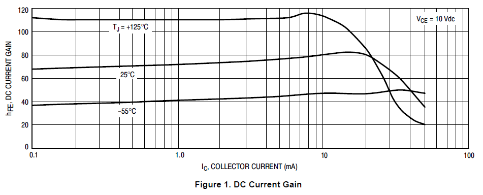
The long tail resistor (offset pot plus the one in series) should drop about 8.xV so Vce(PZTA42)+V(offset res)+Vgs(SiC)=Vg(SiC)-V(B-) //10+8.6+3.2=21.8 For PZTA42, Vce=10V and Ic=20mA is still not out of the woods. Just look at the DC current gain curves in the datasheet below. The non-linear region (due to Early Effect?) is not apparent in the SPICE model from the manufacturer. That's probably why it didn't catch the amp designer's attention. On the other hand, I was probably over worried about exceeding the C2M1000170D's max Vgs rating.
-
I’d plot the attenuation curves of the 4 individual pots and see if I can mix and match to minimize the error in the rotation range I care the most.
-
You won’t be able to swap the channel mapping between the amp and the phone, due to the fixed pin out in the phone cable connector. Since both phones have the same problem with the amp, it’s the amp that’s the culprit. It’s unlikely that the problem can be fixed by feeding single-ended input (RCA). I would get the amp serviced.

