simmconn
-
Posts
173 -
Joined
-
Last visited
-
Days Won
2
Content Type
Profiles
Forums
Events
Everything posted by simmconn
-
A couple of years ago I bought some 2SA1486s from Taobao, the Chinese equivalent of eBay, for about 40 cents a piece. They all check out fine on my Tek 577 curve tracer. I got the green ones with formed leads, likely leftovers from some factories' custom orders. The same picture shows up on Aliexpress. Possibly from the same source. The same seller sold me some 2SA1968s for a bit more money. They checked fine too but looked like rescued from dumpsters. There are many sellers selling fakes, but if you know the right package, the right font, and can tell a grounded and then remarked top surface, with a little luck you can still have genuine parts for less.
-
Typo? Based on your calculations the current should be 0.93mA
-
Nice! Looks like around 2ma would give the least impact to the circuit due to LED aging 😄. Joking aside, the LED part you used doesn’t seem to have a sharp curve. If I’m not mistaken, the LED in the circuit here is expected to act like a zener diode with low dynamic impedance. Maybe it’s time to pick a different P/N.
-
The components will age, LEDs in particular, and accelerated under elevated temperatures. I would check the LED’s I/V curve on the curve tracer before popping it on a circuit. They could differ quite a bit in characteristics even if looked similar on the outside. If a circuit only designed less than 1ma for the LED, that’s likely starving it. I’d make sure the operating current is sufficiently past the “knee” area of the curve.
-
They are the latest Gerber versions but not with JimL's the latest PSU circuit. The PSU Gerber still have the problems I mentioned in my post. It's best to update the layout with the latest PSU or use the more complex GRHVs. Having said that, I still have a few extra boards left over from my build (slightly modified version of the above). PM me if you want to try it out.
-
That's the III/2 and II/2 spec you haven't looked into. II/III is the Overvoltage category, and 2 is the Degree of pollution. Once you find their definitions you can match them with your application and determine the proper voltage rating that applies.
-
I had the opportunity to buy the LSK389s in person from the guy who's selling them on ebay. They all tested good on my curve tracer with Idss in the reasonable range for most applications. I've not purchased any from the official channel such as a distributor. Whoever did that can chime in and let us know where the binning code is printed. I suspect Linear Systems had some sort of lab floor sweeping event about 2 years ago. The above is not the only source which suddenly appeared in the local market. Can you imagine someone approaching you with a gallon-sized ziploc bag full of LSK389s for sale? I was able to get a fistful of them, second-hand. Most of them checked out okay, although very few were in the preferable Idss range. They could very well be factory rejects, but they've served me well.
-
Google “Overvoltage category” and “Degree of pollution”
-
The Boonton should be measuring THD+n instead of purely THD given its vintage and price range. So if your one half has a noise problem it will also show up in the “Distortion” reading. Might be easier to figure out if your unit had the 400Hz high-pass filter.
-
The Boonton 1121 should allow you to do fully differential measurement up to 300V. Did you try that? I measured my unit with SYS2722 and the second harmonic was the only one visible that sits comfortably below -100dB. Too bad I didn't save the test result and the unit is too heavy to move around for retest. The only complaint I had was that 1mV wide-band noise. Compared to the Stax amps this is very good already. I don't remember any single-ended test results. Perhaps I did single-ended input but never single-ended output since that would not make sense. By the way my PSU is set at +/-450V, bias set at 17mA and all transistors curve-tracer matched where needed.
-
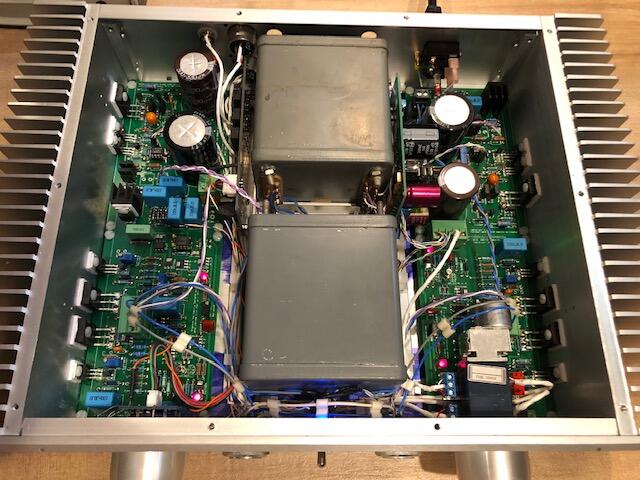
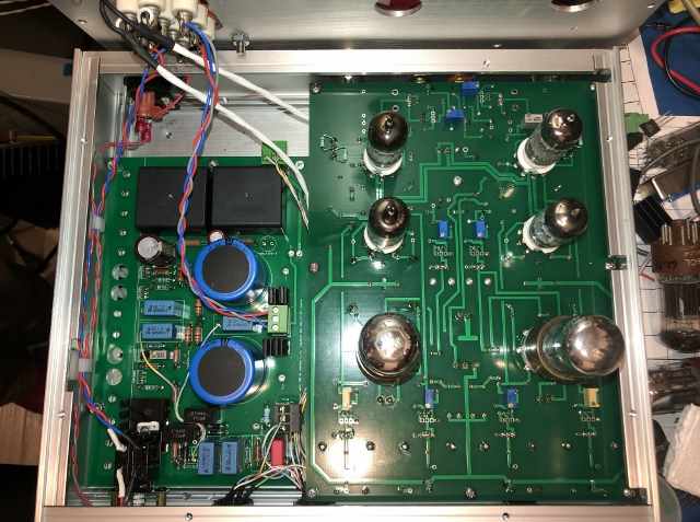
Thanks @Blueman2 for the tips. Here is the internal picture (the file attachment allowance of this forum is ridiculously small!). You can see that I had to cut notches on the chassis and modify a few other things to make them fit. Also low-profile HV film caps are used due to the transformer posts protruding from the top cover. The hum levels of the assembled amp (2.5mV to 5mV) are way below the audible threshold. For the hum to be audible, it needs to be somewhere near 50mV. The wide-band noise of this amps is quite low (<1mV). So higher S/N ratio is possible if the hum is under better control. The surplus power trans has two 6.3V heater windings. One of them was for the rectifier and has high working voltage. I used it for the 6SN7s because it is lifted to near the B- level. The other 6.3V heater winding has a lower working voltage rating which is good enough for the small tubes' heaters when lifted to about 65V.

-
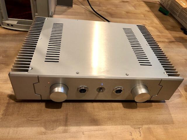
I finished my first SRX+ build yesterday. It is overall quite satisfying. It doesn't have the breathtaking bass or unforgiving resolution of KGSSHV Carbon, but is rather non-fatiguing for long-term listening. I took the SRX+ Gerber file Kevin created (Thanks, Kevin!), added larger footprints in order to use the cheaper tube sockets, TO-92 footprints for the DN2540s and moved the heater-lift resistor dividers to the amp board so the wiring between this and the PSU board can be more streamlined. I also changed the small tubes to use 6.3V heater in order to match the surplus power transformer. The PSU board from Kevin follows JimL's original shunt PSU schematic. I added a normal bias tap in the zener diode string with a copied low pass filter, different lead spacing support on the output film caps in case a certain part number is out of stock. It is also cut short 1/2" from the original. Got too aggressive in fitting these boards into the small chassis. The internal space is barely large enough for the two boards to lay side-by-side. Had to mill off internal supports here and there, and ended up not having enough space for a real volume pot (the place holder is a rotary encoder waiting for a future attenuator board. The build started with a faint hum. Swapping tubes can reduce it to a certain level. Then I found a 55mVp-p saw-tooth ripple on the power, which is not supposed to be there (the shunt PSU has >120dB ripple rejection at power line frequency according to simulation). It turns out, the bias circuit voltage doubler drops its leg on the virtual ground and injects >1mA of ripple current, because the bias has to be ground-referenced. The virtual ground is not really a low-impedance node (about 60 ohm @ 60Hz with two 22uF caps). Any noise on the virtual ground is considered common mode to the shunt regulator, and is pretty much out of the control loop. Besides, with transformer HV voltage suitable for this design (I used 600V center-tapped), the voltage doubler doesn't have enough juice such that the 10M90 bottoms out at the low voltage points. So I modified the bias circuit to have its return tied to the output B+ and let the shunt regulator deal with the ripple current. Pro-bias is still easy to obtain, but the normal bias would have to come from dividing the B+ like in the original SRX circuit. The final assembly has 2.5mV hum in one channel and 5mV in the other. I don't think I can reduce them significantly beyond that without using DC heater and take care of the common mode noise from the header windings, perhaps also need to shield the small tubes. There is always some coupling from the heater to the cathode and it varies from tube to tube. With multiple tubes sharing the same AC heater I don't think you can balance it out completely using a pot, either. This simple amp performs well, THD+N is as low as 0.01% between 35dBV and 45dBV (40dBV being the rated operating voltage for the SR Lambda Pros to output 100dBSPL, which is pretty loud). One thing I'm not too happy about is the -2dB drop @ 20kHz when loaded with the AP (200k ohm + 66pf including cables). So I played a little with the open-loop performance. The driver stage has only -1.4dB drop @ 20kHz when disconnected from the final tubes, but the Miller cap of the 6SN7 is killing the high output impedance common-grid driver stage, dropping it to -9.5dB @ 20kHz. Negative feedback helped but didn't bring it back to ruler flat. It might help with a cathode follower stage before the 6SN7 but then there goes the simplicity. A rolled-off top end could explain the more forgiving sound, though. Thanks again to Kevin and Jim to make this such a fun project. If you are going to build it, I'd suggest using Jim's Revised shunt power supply for SRX Plus or any other dual voltage regulators. And don't use a chassis too small!
-
550-380=170 not 230. Either you got your zener diode string order wrong or the top 110V zener is way off.
-
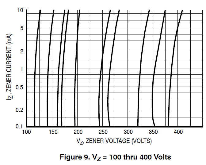
@dingding123 Why don't you measure the voltage drop on each zener diode in the chain, and find out which one is out of tolerance and giving you a higher voltage than it should? You didn't tell us the part number of the zener diodes you used. Let's just use the On-semi 1N5952B (130V, 3W) as an example. The datasheet has the nominal voltage 130V, +/- 5% specified at 2.9mA: https://www.mouser.com/datasheet/2/308/1N5913B-D-1801544.pdf and the curve below shows the zener voltage goes lower as the current drops (1N5952B would be somewhere between the first and the second curve from the left, following the same trend). So you would be expecting lower voltage drop at 1.3mA than you would at 2.9mA. Of course your parts may vary, but the answers should be in the datasheet of the parts you used. Did you also verify that the current source did give you 1.3mA? Measure the voltage drop at the resistor coming out of 10M90S K terminal, and use ohm's law to calculate the current.
-
Have you tried swapping the channels and see if the problem follows the left channel amp or the left phone? If some leakage exists in the phone, raising the offset reduces the effective bias and hence you get less arc-overs.
-
Finally finished the installation of my AliExpress KGSSHV Carbon into a proper enclosure. I wanted to use a somewhat slim chassis so I skipped those taller ones (100mm+) and ended up with the Breeze Audio SD4309B. It's inexpensive (about $57) and has a pretty solid build. The internal space is just enough for the AliExpress/eBay Carbon PCBs, but a bit shallower than the transformers I have. I had to mill 1mm-deep 'pockets' on the bottom cover for the transformers to fit right below the top cover. I'm not a big fan of the heat spreaders so those sections of the PCB were cut off. Aluminum angles were used to build a 'cradle' for the transformers that also work as mounting brackets for the extra boards (input switching and LV power supply). I soon realized that the boards are not so DIY-friendly to work with. The Golden Reference HV PSU board is not designed for center-tapped HV winding which is more popular in surplus. The connectors are somehow placed at the convenience of the PCB routing but not so much for harness routing. Shared terminal pins means that you'll often have to stick two or more wires into the same hole, etc, etc. Not having a mirrored pair of boards seems to make things worse at some places but otherwise not a show-stopper. I was planning to make this a phase 1 project. The phase 2 will have the input switching and volume pot changed to rotary encoders driving digital pots, which will then make space for phase 3, a tube final stage piggy-backed on top of the carbon PCBs, could be BHSE or Grounded-Grid. There is enough space left, but I'm afraid I won't have the time. Just some ideas for more ambitious builders, I guess.
-
@cloudhead Thank you for putting together the netlist. I appreciate your time. If I may nit-picking a little bit. If you would like to do harmonic analysis on the differential signal, you could use '.four V(out+,out-)'. Using .four V(out+)-V(out-) will get you the analysis for the single-ended V(out+). You can see the session error log for details. The HV power supplies starts at full voltage and drops to zero within a few ns at the start of the simulation. This causes a large current spike through the body diode of the SiC devices. This is probably an artifact due to the HV supplies' behavior in the simulation. I don't think this is real, but it does prompt me to look into the power on/off transient behaviors of the circuit as I look for alternatives for the SiCs. They are too expensive, have a positive tempco, and are not strictly DC SoA rated.
-
Megatron Electrostatic Headphone Amplifier
simmconn replied to kevin gilmore's topic in Do It Yourself
I'm not sure if I understand your reply. In the Megatron the first stage uses 12AU7, and the second stage uses 12AX7. What do you mean by "provide 24db gain to drive pair 12au7s"? -
Are you talking about the partially overlapped double holes for the C2M1000170D? I guess non-plated, oblong holes would work better, but somehow the layout person got sloppy and slapped on two plated holes (pads).
-
Megatron Electrostatic Headphone Amplifier
simmconn replied to kevin gilmore's topic in Do It Yourself
I was wondering... why the first and second stages are designed at such low operating points. 12AU7 is at 1.2mA and 12AX7 at 0.5mA. Wouldn't higher operating points give better distortion and lower output impedance and hence better frequency response at the higher end? -
Oh I'll definitely put these in a proper enclosure with volume control and input selection, etc. This is just temporary. By the way, do you have any suggestions to reduce the gain? Increasing the NFB would certainly do it. I'm more looking for a way to reduce the open loop gain I guess.
-
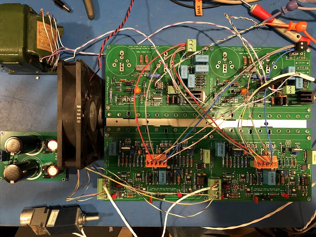
I built the amp on a heat sink taken from an old Denon home theater receiver, and decided to try it out before investing more time and $$ on a 'real' enclosure. It just so happens that the heat sink has the exact length for two boards mounted side-by-side, and width to mount the transistors on both the PSU and amp boards. The big electrolytic caps are mounted on the opposite side of the PSU board to double as temporary mechanical support. You can see the green Soviet military style HV transformer. I got it a number of years ago on ebay when the international shipping wasn't that crazy. It's better suited for circuit requiring 400V or 350V B+, though.
-
I just finished building the KGSSHV Carbon and Golden reference PSUs, well, using the PCBs from AliExpress. The performance is superb. It registers 0.0006x% THD+N up to 583Vrms and the distortion profile is very well behaved (2nd order slightly higher than 3rd order). The noise floor is at 1.1mVrms wide-band without power-line frequency harmonics. I found that my comfortable listening level is around 10Vrms and would probably never need that kind of dynamic headroom. Is there a lower gain option or mod that can bring the noise down?

(640x401).jpg.6e1f25f76808dbebb769628f65303026.jpg)