kevin gilmore
High Rollers
-
Joined
-
Last visited
Everything posted by kevin gilmore
-
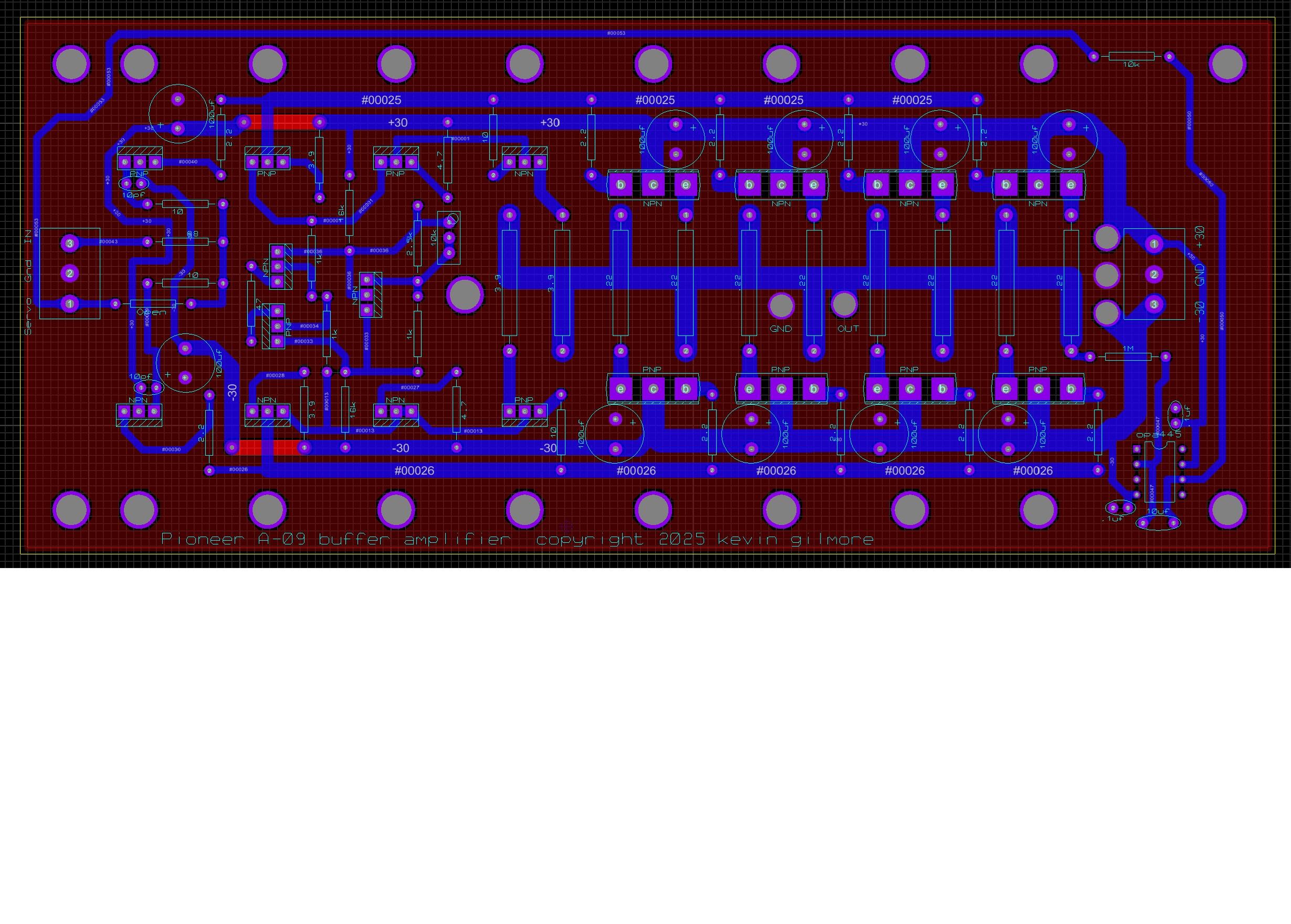
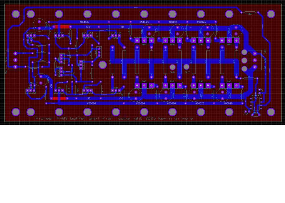
Saw some talk about this and decided to make a new version. use either the tube unbal/bal to bal board, or the solid state version result is about 125 watts rms into 8 ohms at thd of .005% will definitely drive 4 ohms with suitably large power supplies. transistors are standard pinout, so pick your favorite output transistors. the to220 transistors are mje15034/mje15035 perfect for so many things, including esl boost transformers. pioneera09.pdf
-
you should see some of the chinese cfa3 ripoffs for around $1600. one in particular is fairly decent, the rest are trash. just wait till the chinese start selling the D&G clones. running with multiple >1kv power supplies. what could possibly go wrong.
-
being retired means i get to do what i want to do and when. so the new thing based on the pioneer a09 (no not the a9) is also zero feedback, 120 watts into 8 ohms, damping factor of 100 and a thd about .001%. the absolute perfect thing to drive your lundhal electrostatic transformers. basically the exactly same ubal/bal to bal board in the cfa3, and then the high power buffers. pair of 30v 20 amp switching power supplies.
-
i am retired now, 7+ years. And loving it. Due to arthritis issues i am no longer working on any more equipment. including my own. going to pay a couple of high-school kids to stuff and solder boards and chassis etc for new projects.
-
has to be one of the ones that can be set to 12v like this Amazon.com: FARSENSE USB C to DC Adapter,Barrel PD Trigger Cable(3.3ft) with 10 Connector Tips,USB to DC Power Cable can Switch Voltage by Pressing The Key,Support LED Display Voltage : Electronics
-
at the moment, do what i did 30 years ago. srm212 plus 12v 7ah gel cell. its portable. kinda portable. or buy 4 x apex opamps and run them class C with the dc to dc converters. i wish i had a better solution. getting all those transistors to touch the heatsink at the same time is not easy. even the koss box requires a decent size battery. (6 x D cell)
-
no, omega-els has the hvrv-hansen portable. and the power supply blew up. so he is using outboard dc/dc converters to power the no longer really portable thing.
-
i looked at the ltspice file for a bit. best guess is that there is something wrong with the jfet model that causes issues. replace the fets with bipolar and see if it works right. the reason all the darlington transistors are on the heatsink is so they can thermally track. effects thd. another thing that really effects the thd is the power supply rails. anything under +/-20v is too low and causes much higher distortion. +/-30v is the sweet spot. and once you do that, you end up with an amplifier that is a lot more than 5 watts. in your second schematic, you have taken out the low impedance load on the output of the current mirrors. lots more voltage gain resulting in required high amounts of feedback. definitely not the original design goals. if you want lots of open loop gain, probably best to pick a different design. as far as the bias servo, would have to see thd with and without it.
-
assuming the parts are stn9360 and matching npn are 600v parts the front end limits to +/-600v. with cascodes you can get to +/-900. anything over +/-600v will damage the headphones.
-
that is a dual voltage output, single ended flyback supply. can't change the positive voltage without changing the negative. so you really need 2 x single output units. and then you might be stuck with +/-380. which should work.
-
so my version has an amplifier power of around 20 watts. the hvrv version seems to be half of that. may be the reason why there were a couple of comments about the sound vs the original to126 version.
-
those modules do work, i have a few. the diodes on the back run stupid hot. never tested for hours and hours. there was a company in poland i think building an electrostatic amp with 4 of these. first version with no fans. second version with fans. both versions burn up in a couple of months.
-
the dexu parts are providing the isolation. this works. extra parts, maybe the same performance.
-
those are not isolated. at least they sure look non isolated. how you put them in series with common power supply input.
-
links for those power modules please. how warm does the chassis heatsink get? edit: what is the total power input that runs the switchers?
-
the power supply shown is definitely a flyback single ended switcher. which means the 2 rectifier diodes see twice the power than a push pull switcher would generate. which means its going to get hot. diodes need to be increased in power handling. would like to see a real picture of the amp board in as high resolution as possible.
-
surprisingly on something like a 727, the peaks are already clipped at moderate volumes. so this will let all the wonderful dynamics thru. and damaging you hearing, definitely.
-
max voltage swing is 4 x bias. so 580 x 4. the amp does loose about 20 volts of voltage swing, so 600 is a nice number. same voltage the koss uses. also the rating on the pnp transistor. could cut the voltage to 550v for a bit more margin.
-
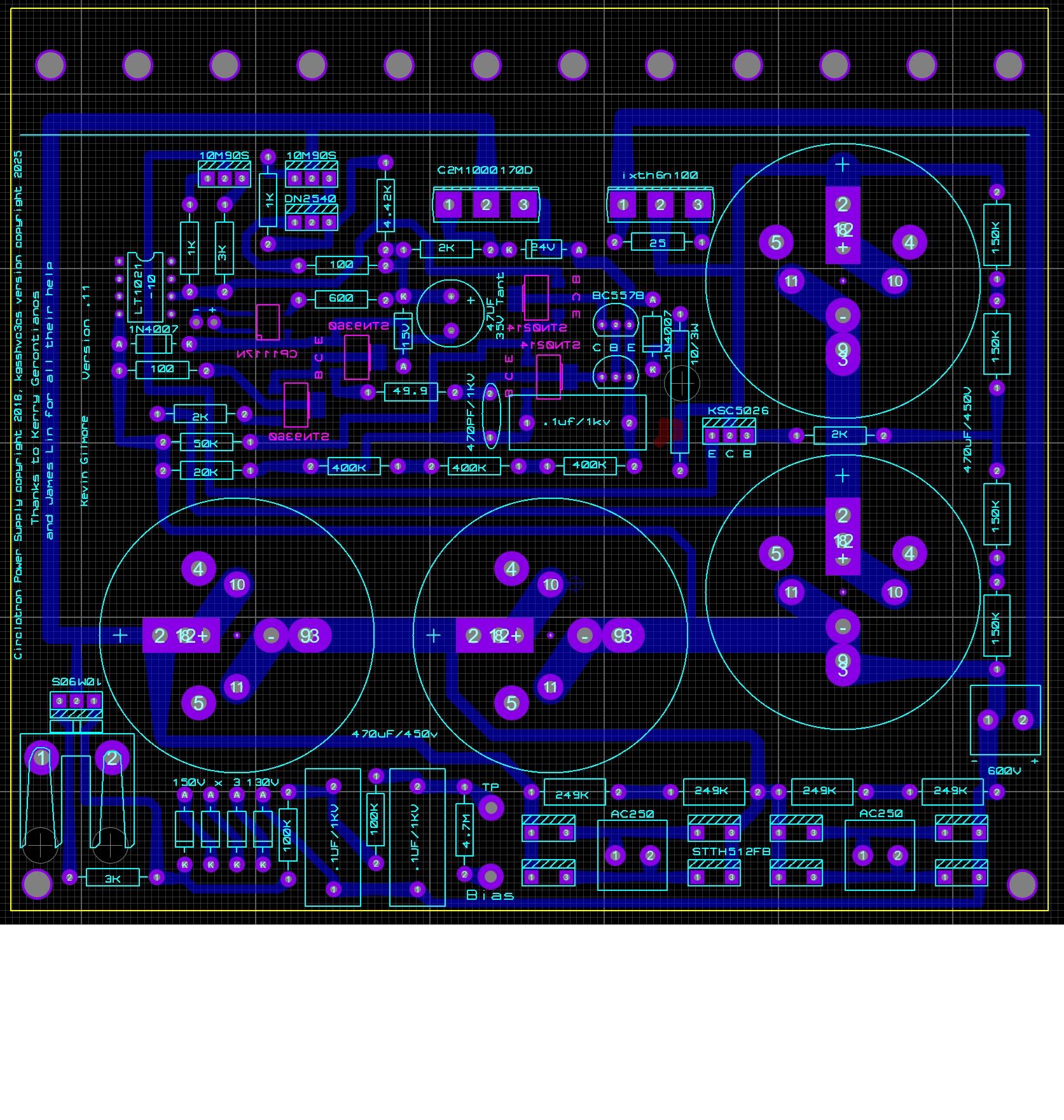
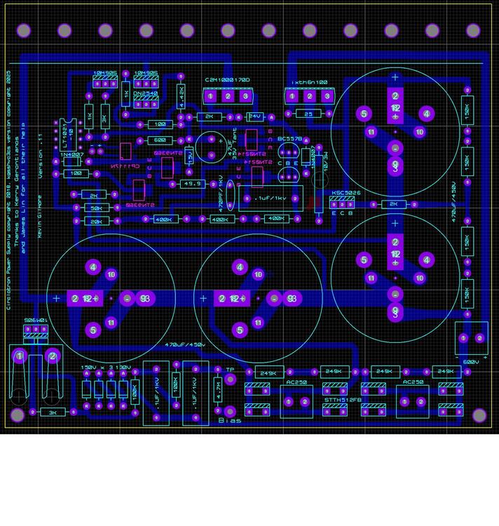
power supply schematic updated. amp board updated. circlotronpsupdated.pdf kgsshvcarbonv6.1c3cs - CADCAM.ZIP
-
q12 is the current limit. so if the amp board shorts, at least the power supply will not explode. what do you want me to replace the pzta part with? remember 20+ma
-
definitely has enough power for that. 2400 volts peak to peak stator to stator at 25ma bias. only otl dc coupled solid state amplifier design that can do this.
-
and the power supply that goes with it. standard off the shelf antek transformers are $44. need 2 schematic fixed. kgsshv600vpower - CADCAM.ZIP circlotronpsupdated.pdf
-
i know that birgir has a new batch of megatrons, do not know if they are all sold or not has to deal with eu rules. soren is also making megatrons also has to deal with eu rules. headamp has amplifiers, dont think there is an export tariff so this might be a bargain. there is a guy in california that i cant remember who is doing custom megatrons.
-
So there is this manufacturer out there that puts a solid state otl electrostatic amplifier in the same box as a high output dynamic amplifier. For a whole host of reasons this just seems stupid. Instead of 1 thing well, lets do 2 things poorly. The first version of the woo audio did indeed use a single tube as a cathode follower into the same apex high voltage opamps. and boy did woo audio turn colors when this information surfaced. So they tripled down on the stupid this time. options include 1) all tube 6sn7 -- 300b -- transformer -- headphones 2) solid state -- headphones 3) 6sn7 -- solid state -- headphones at least that is what i think their advertising goo says. and whether they are lying this time. There are 4 different versions of an all tube megatron that you might want to consider instead.
-
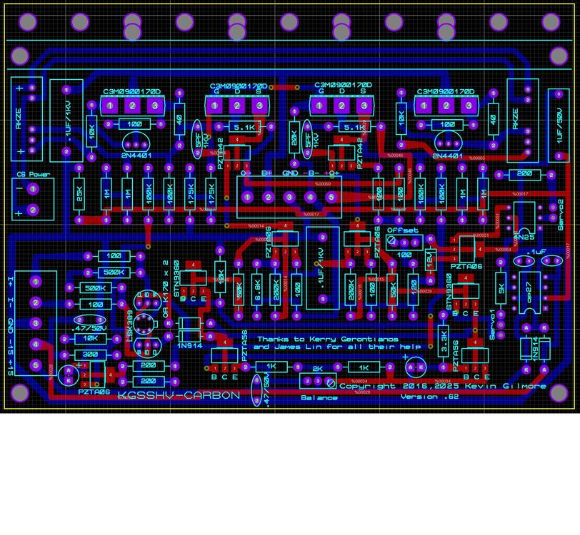
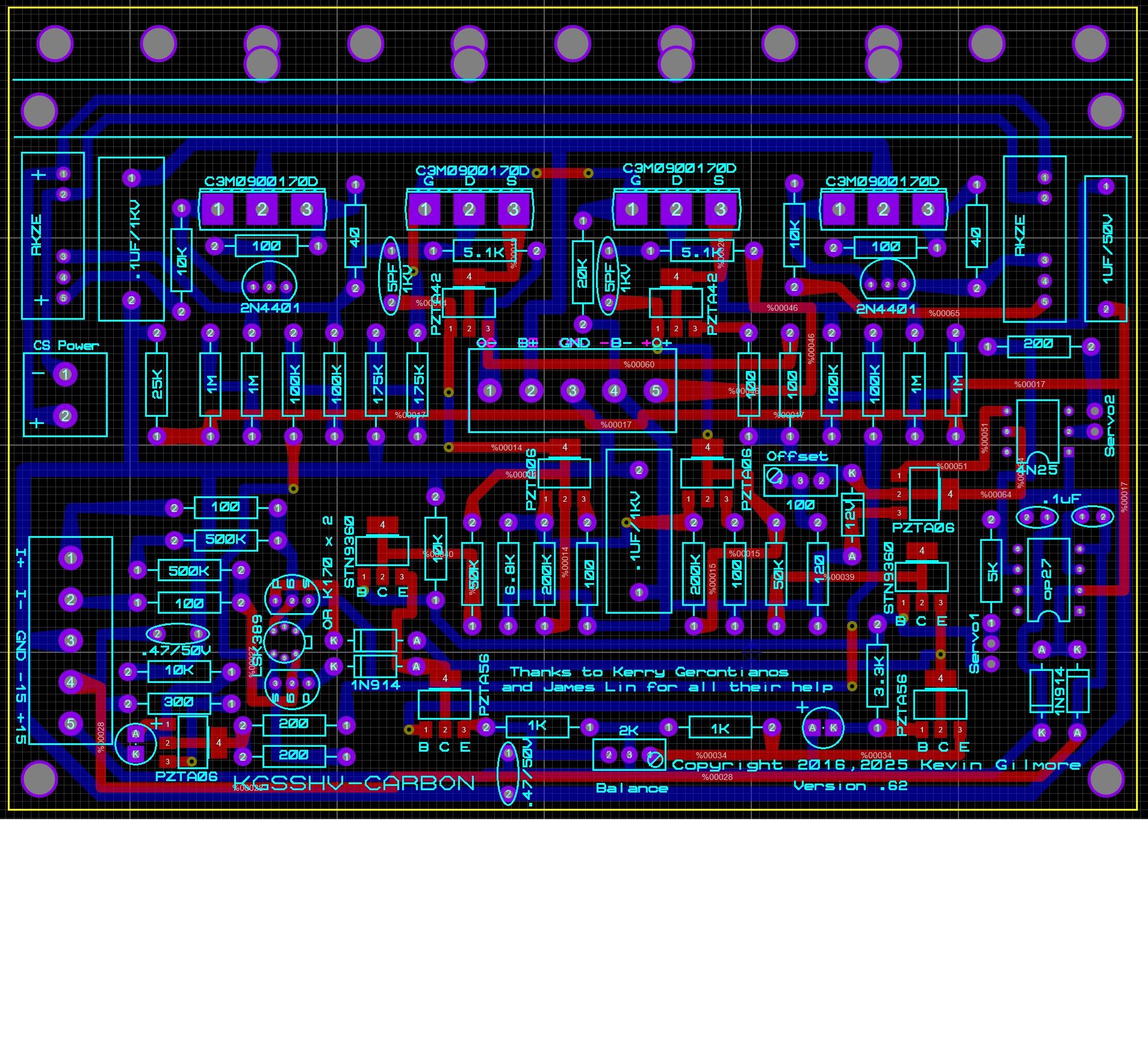
so here is the latest version of the kgsshv-carbon with the c3m series parts including the current source. Good for up to +/-600v power supplies. board file updated. kgsshvcarbon600v.PDF kgsshvcarbonv6.1c3cs - CADCAM.ZIP