kevin gilmore
-
Posts
7,204 -
Joined
-
Last visited
-
Days Won
21
Content Type
Profiles
Forums
Events
Everything posted by kevin gilmore
-

Feliks Audio Bliss - so much stupidity...
kevin gilmore replied to spritzer's topic in Headphone Amplification
can't find any internal pictures. but a 6ca7 as a current source for a 300b has plenty voltage swing, more than 1600 volts is possible. but the front end is lacking in voltage gain. so you are definitely going to need one of those 10v output dacs. -
you forgot the dn2540 cascode on the 10m90s
-
finally an electrostatic transportable
kevin gilmore replied to kevin gilmore's topic in Do It Yourself
updated board file, 10k input resistors added (optional) and 25k changed to 17k cfaelectrostatschem2-4 - CADCAM.ZIP -
the neutrik jacks i used in the diy t2 are actually 4 wires. the connector shell is a seperate wire. i put in a jumper to chassis ground for that wire.
-
relays are dual coil latching. so 2 might be tricky. 3) lots and lots of cheap transistors. best to go with the "B" versions, matching is always better. 4) 50k attenuator NOT NEEDED. thats the point. there is no commercial product with an output voltage that will saturate the input. 5) very much like the ayre kx-r. individual resistor goes between the 2 pins. for increased gain should you want or need it. schematc shows everything at 0db gain.
-
only need one power supply for both channels and its not a lot of power. also runs whatever microcontroller you decide to use.
-
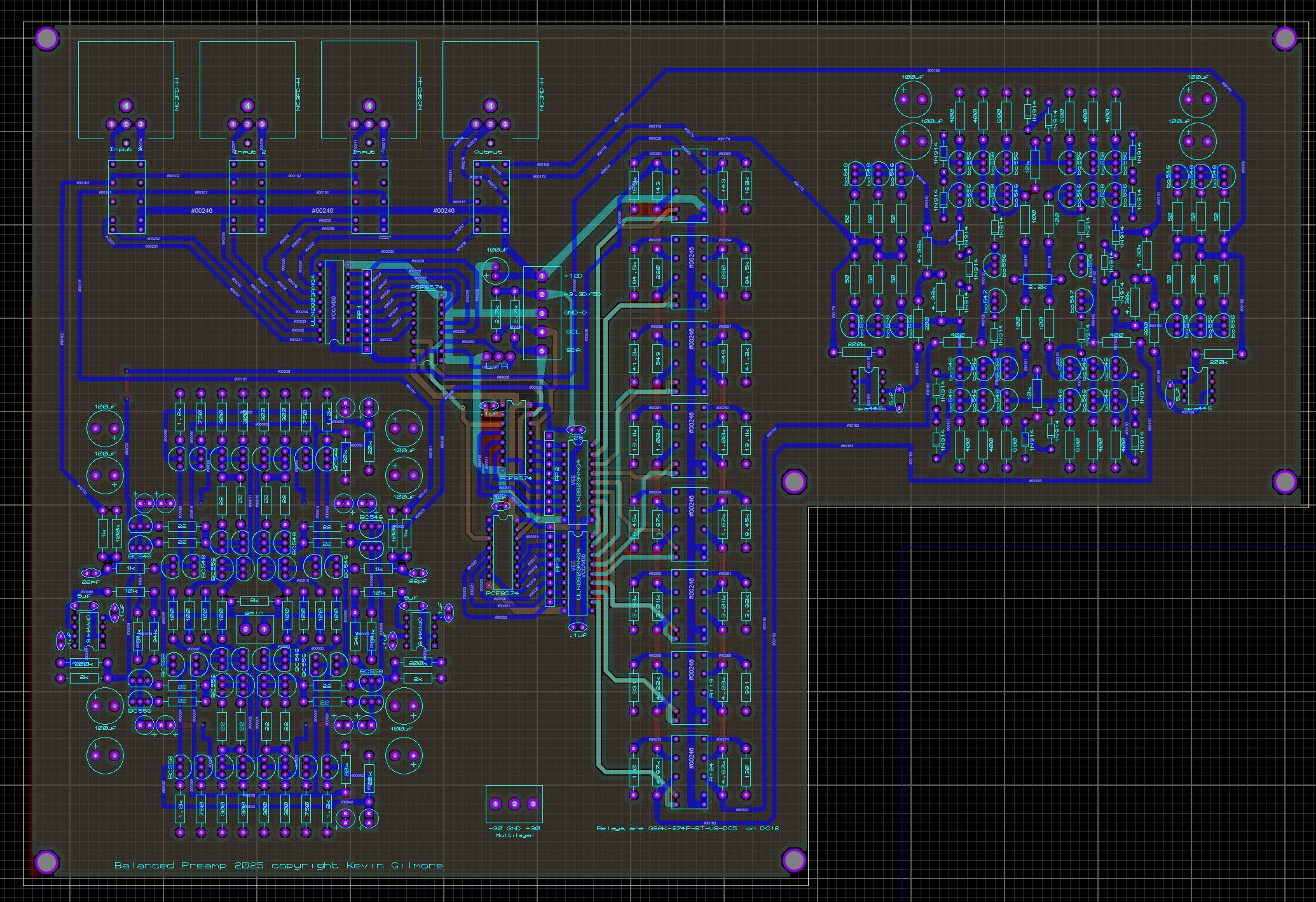
possible final version, 4 inputs and the xlr jacks correctly located preamp2025i - CADCAM.ZIP
-
this version should be compatible with the amb lcduino software with no changes. preamp2025h - CADCAM.ZIP

-
soren asked for the board with onboard grlv preamp2025g - CADCAM.ZIP preamp2025g.PDF
-
for clarity this board is mono. 2 required for stereo. boards stack. needs arduino software, or equivalent programable controller.
-
board file and schematic preamp2025f.PDF preamp2025f - CADCAM.ZIP
-
actually the bryston uses that scheme.
-
the idiot at eddie current was big on that circuit. and did that on his electra. and then tried to get too much gain out of it. and the tubes went into saturation and then you have to hand pick the tubes etc. biggest problem with that one is the 100k pot starts off with 2nv of noise all by itself.
-
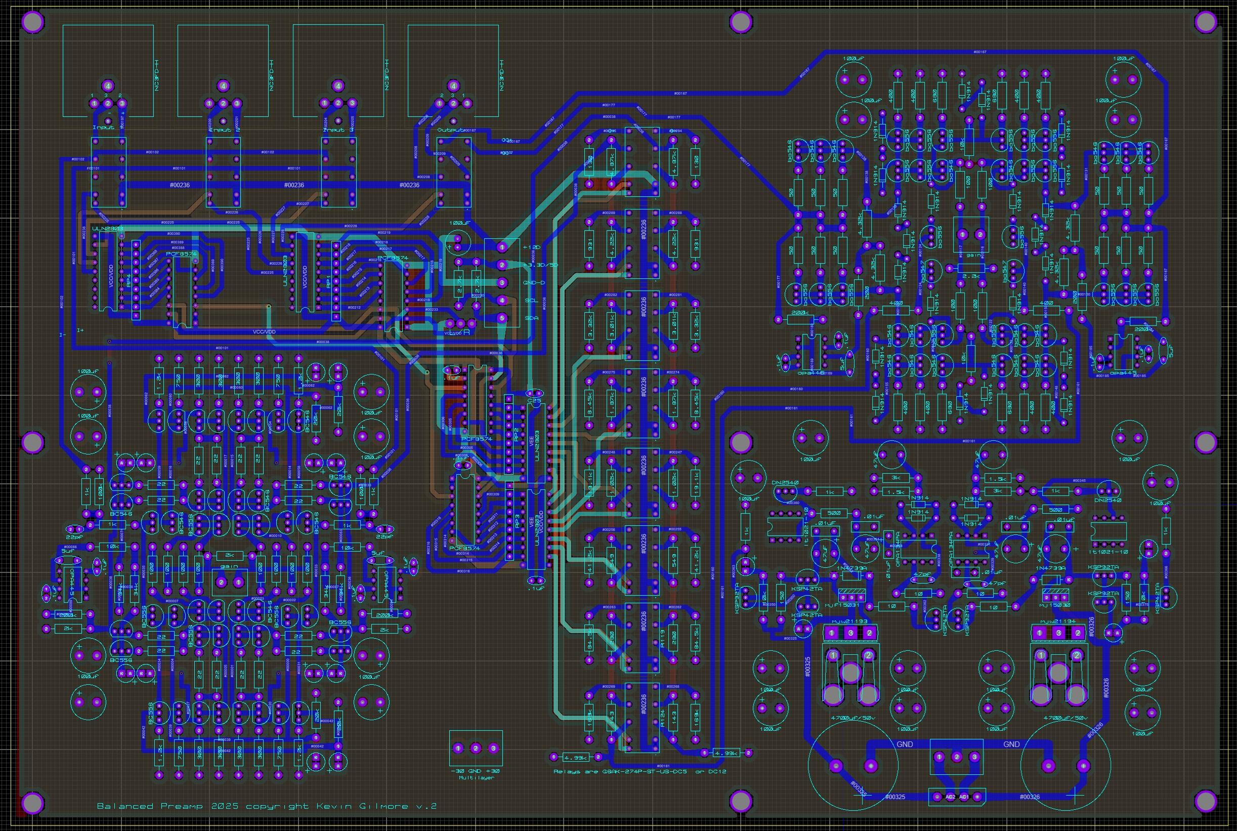
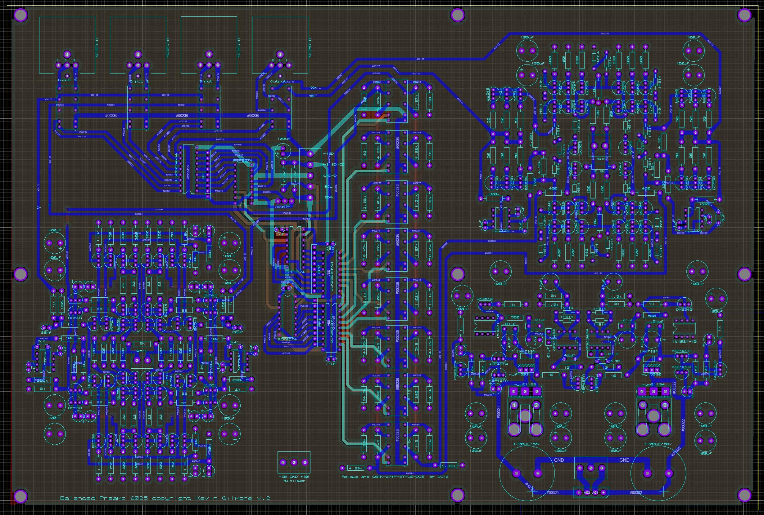
its not obvious what this is? first stage is the input section from the uberamp 2. current mode voltage gain. (not that you actually need voltage gain) differential input, differential output. then balanced step attenuator. constant input impedance load. output stage is the same input section with the darlington input removed because its not needed and some of the cascoding removed because its also not needed, tied to a voltage buffer. many of the expensive preamps out there convert everything to single ended internally to save on parts and board space. this is balanced from input to output. and 6db or more less noise. many features of preamps of the past include things that are no longer useful. so they are removed. like tape out and second zone. seriously i have never heard of anyone actually using second zone. and except for the really expensive ages old professional gear, there are no tape machines with balanced inputs. maybe the new revox has balanced inputs. so consider it as a balanced buffered volume knob. turns out the signal to noise boost really is audible. krell fpb600 vs mc611. more than 12db signal to noise boost on the mc611 partially because of the low input impedance and rail to rail input buffer.
-
finally. higher signal to noise ratio, more than 110db. takes signals up to 20 volts peak to peak unbalanced, 40v peak to peak balanced. no input attenuator that adds noise for those stupidly high voltage dacs. ( requires 30v power supplies) (volume control in the middle) thd about .005% no feedback. work in progress 4 layer board. preamp2025f.PDF
-
thorens td125 with sme type 3 tonearm. mcintosh c26 preamp mcintosh 2105 power amp teac reel to reel. classic stuff then. classic stuff now.
-
finally an electrostatic transportable
kevin gilmore replied to kevin gilmore's topic in Do It Yourself
there is an american manufacturer of the same power supplies, same foot print. about double the price. don't remember where. i have too many new toys to play with at the moment. one makes 116db on startup. its pissing off the neighbors. (which is a good thing) -
Megatron Electrostatic Headphone Amplifier
kevin gilmore replied to kevin gilmore's topic in Do It Yourself
somewhere there is a mini board that is a stn9360 to to126 pinout. but bending the pins is something i have also done. -
Megatron Electrostatic Headphone Amplifier
kevin gilmore replied to kevin gilmore's topic in Do It Yourself
the 2sa1968 is definitely a pnp. there were datasheets that were definitely wrong. for this application you need a 400v pnp. -
Megatron Electrostatic Headphone Amplifier
kevin gilmore replied to kevin gilmore's topic in Do It Yourself
definitely not. use ksa1156. not sure if its the same pinout. kind of busy at the moment. but you would not know that -
Megatron Electrostatic Headphone Amplifier
kevin gilmore replied to kevin gilmore's topic in Do It Yourself
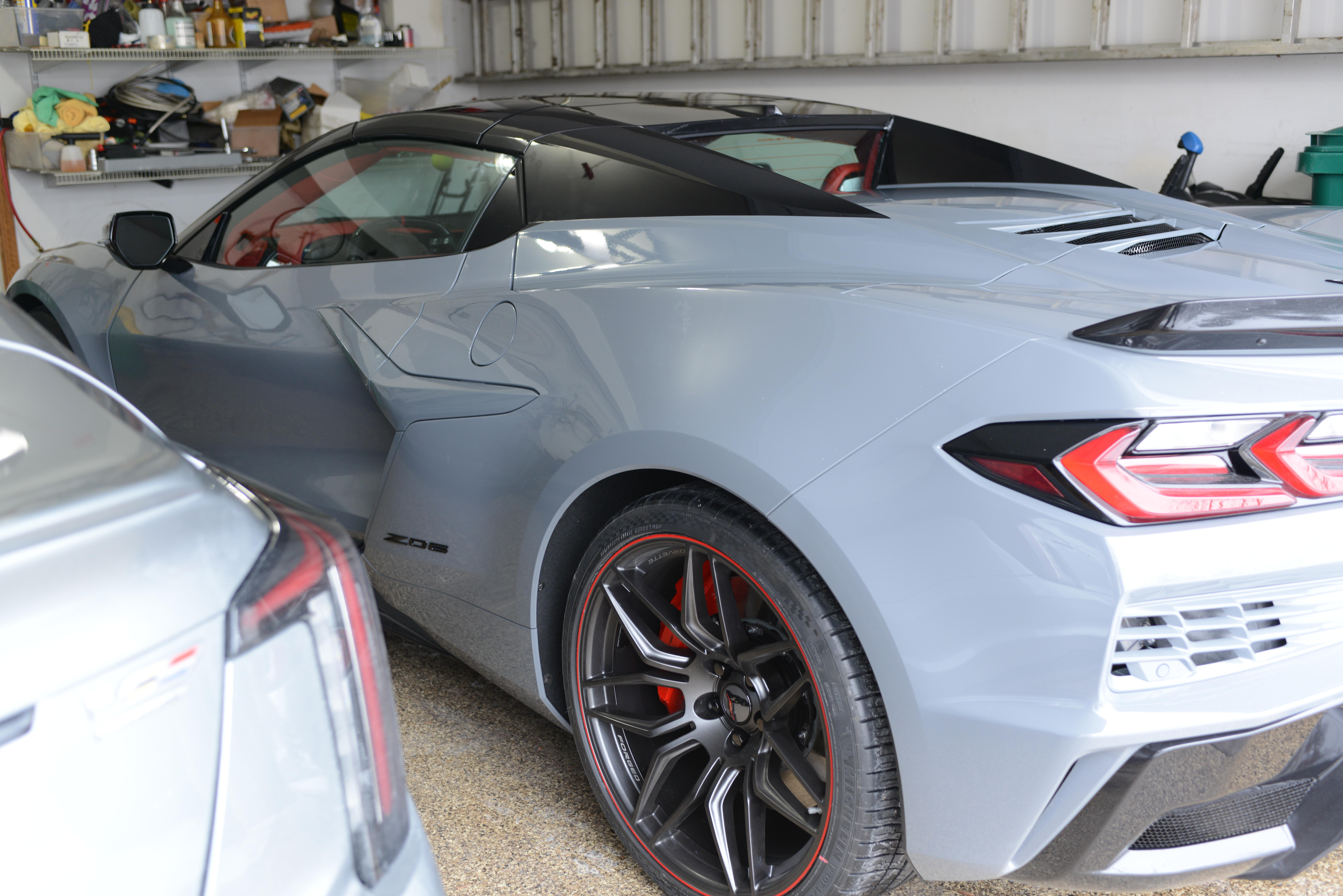
going to look at it in a few minutes. should be ground i think. nope, thats the feedback on the output. and the gerber file is correct. not sure where you got that picture, probably here, and likely not done. 3 of the other versions had the same error, all are updated on the google shares. no idea how that happened. someone needs to go thru all 9 versions (or more) to see if there are any more errors. i'm kind of busy waxing my brand new 2025 corvette Z06 3lz htc.
-
12 volt filament version with pin 6 grounded. for existing boards modification is easy. solder short wire from pin 6 to the ground pin on the .1uf 630v cap nearest to that tube. megatron12vcs - CADCAM.ZIP
-
will look into the megatron boards and see if the mods are easy. likely they are.
-
since pin 6 of the tube is a no connect, you can modify the amplifier and tie the 4 pin 6's to chassis ground. then in the adapter, pin 6 to the heatsink.
-
great idea. but there had better be a tail to ground the heatsink. otherwise not safe.