Craig Sawyers
-
Posts
5,495 -
Joined
-
Last visited
-
Days Won
33
Content Type
Profiles
Forums
Events
Everything posted by Craig Sawyers
-
Ah yes - Clive Sinclair. Back in the day (late 60's early 70's) and always trying to minimise costs he would acquire hundreds of thousands of reject transistors free. His team would then test every one to find the few that actually worked OK to use in his products. The reject transistors were used in the foundation for his driveway.
-
I guess there was a moment for all of us that got us interested in audio, electronics, science and so forth. To kick things off, this was got me going. In the UK during the 60's and 70's there was a series of educational books for children called the Ladybird books. It eventually ran to hundreds of topics, but were written in very clear language and with superb illustrations. It shows what an effect this had on me - I remember precisely the book - Magnets, Bulbs and Batteries. And thanks to the web, here it is www.vintage-radio.info/download.php?id=358 vintage 1962. I remember pretty much everything I built from that - and from the publication date I must have been 7 or 8. The one I remember particularly was the electric motor made with a cork, some needles and pins, a few paper clips and wire, and a battery. The only bit I needed help with was pushing the needle through the cork, but only because I did not have the strength. So what moment got you interested?
-
I'm replacing Quad ESL 57's equipped with my own dipole subs, so I have a known and very neutral reference with which to compare. The main problem with the ESL's is that to image properly needs very careful set up, and a sweet spot that needs your head fixed in a vice (or vise depending on the side of the pond). I seem to be making a habit of dipoles - going back from the Quads, Podum 1, Martin Logan something, Magneplanar something. Mind you I have heard some spectacular box loudspeakers (the best was the Rockport Arrakis) in the airy price stratosphere, and way out of my pay grade.
-
They look really interesting modules; loooong thread though, 127 pages in about a year. Self is not without his quirks - he is very anti FET and anti AB - although the performance figures of the current modules in your link have superb performance. Don't underestimate the influence of power supply wiring - the half wave rectified currents in +/- power supply leads to the amp can induce significant excess distortion.
-
Yeah flat pack would help. But not for me - I started with two 8 x 4 sheets of marine ply and did it from first principles. I've gone for Douglas Self blameless. Each bass driver gets a load-invariant amp (four in all) with a measured output of 175W at 4 ohms each. Mids and highs get a compact blameless, which still does 175W into 4 ohms, but with more distortion that the load invariant. They are all Class B. Measured distortion at 50W 8ohms, 80kHz bandwidth and RMS sensing is 1kHz 0.0028% 10kHz 0.0040% 20kHz 0.0056% But the residual distortion of my set up is 0.0027%, so the actual harmonic distortion is pretty insignificant. In hindsight I might have gone for his "trimodal" design. That has a switch to select either Class B, or Class A/AB. In A/AB mode it does 30W class A and then changes to AB from 30W to 100W. So easily switched to Class A/AB for the tweeters.
-
I'll be able to tell you in a week or less - just finishing the second four-channel power amp; final wiring underway. I can tell you that they are not a project to be undertaken lightly - it is an expensive and complex project. Drive units are nearly a grand (in UK pounds) alone $1600 in the US. The bass units are the most expensive of the drivers, because they were made to Linkwitz's spec. The woodwork is complex, but flat-pack kits are available from Madisound in the US https://www.madisoundspeakerstore.com/cabinets/lx521-linkwitz-lab-flat-pack-cabinets-%E2%80%93-pair/ and http://www.magiclx521.com/lx521-components.html in Europe.
-
The original SRM-T2 had many of the active devices mounted on isolated heatsinks
-
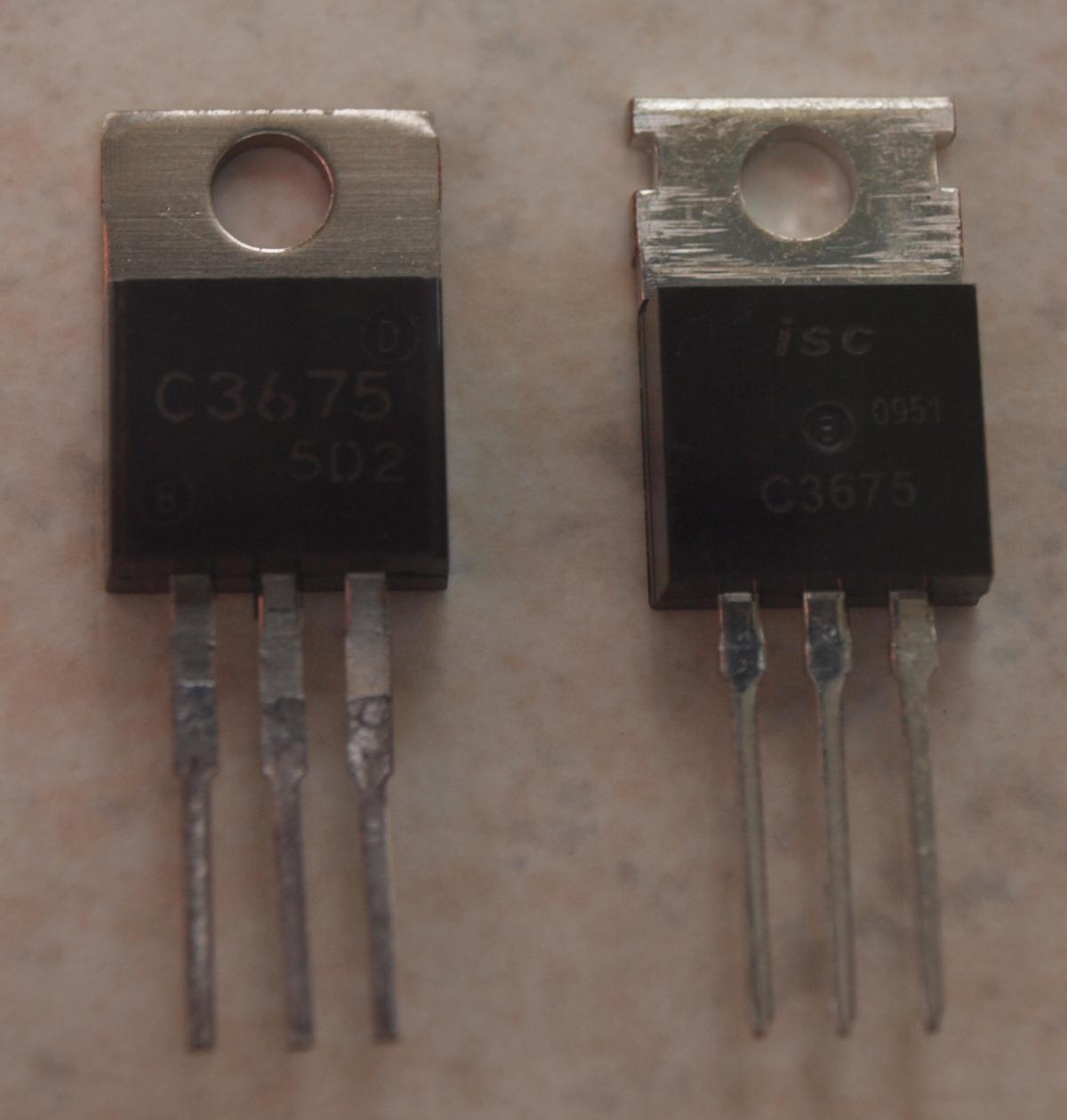
Dunno why the pics are dead. Attached below. I *think* the one on the right was the fake. Breakdown voltage was far too low - heaven knows what POS silicon is actually in the package.

-
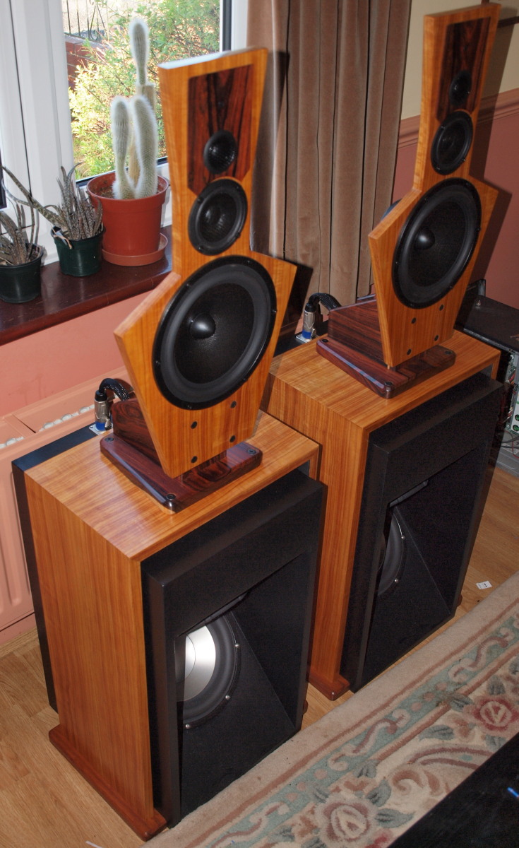
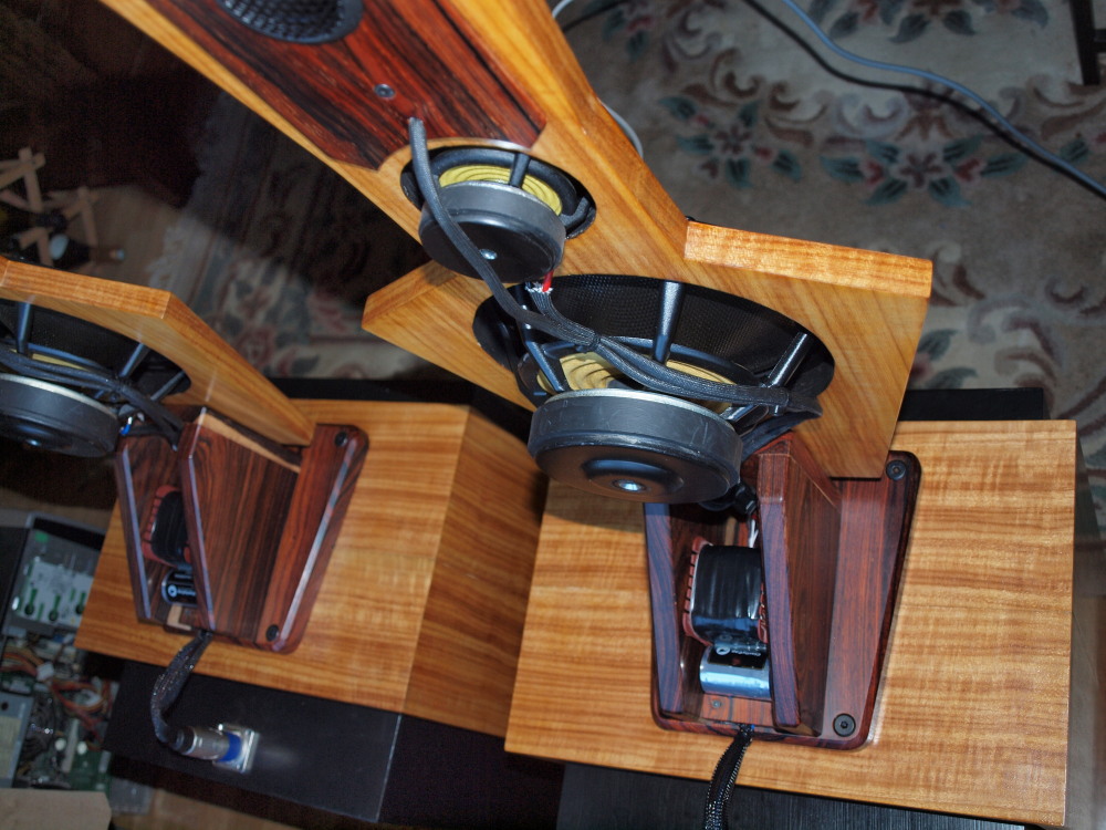
Thanks guys. There is actually a story here. Four or five years ago I had a bout of flu, and to see how I was recovering I went for an early walk one day. I fell to thinking about my old dad, who had always expressed an interest in learning to paint. We bought him a starter kit, and in the end he went to his grave without ever having opened the box. Actually, he was probably scared of trying and failing, and didn't book to go on a course to learn. Anyway, one of the things I had always wanted to do was learn cabinetmaking - and that walk in the spring sunshine gave me the moment of clarity - I was not going to go to my maker without learning. So I booked a course - in the end 6 weeks taken in 1 week chunks, with a cabinetmaker in Ross on Wye (UK). I left there was a set of oak drawers, currently in our bedroom, hand cut dovetails etc etc - the kids are in competition who gets in when I pop my clogs. The speakers are the latest think I've built. Apart from the rear support frame and the tweeter sub-baffles, which are solid cocobolo, the rest is baltic birch marine ply. The dipole bass unit is painted with black milk paint, and the top panel and bridge are veneered. That gave me the opportunity to learn a new skill. It is done traditionally using hot hide glue. I then French polished them with lemon shellac - again a new skill. Most importantly - my significant other likes them. Mind you I've inflicted some pretty outrageous speakers on her over the decades, but it is something of a relief after so much work that they get the thumbs up!
-
What I just built. Linkwitz LX521's. Electronic crossover built, just finishing the second four-channel power amp to drive 'em
-
I populated my build with fake 3675's. Generated frightening cracking sounds and sparks. Took out a bunch of FETS as collateral damage. With good parts it hasn't missed a beat. I also got some fake FET's too that did not make the build. All from Dalbani in the UK - be warned.
-
Wrong on so many levels
-

The Knuckledragger 3rd Memorial Slow Forum Post
Craig Sawyers replied to Knuckledragger's topic in Off Topic
Good god - I'm astonished that was survivable. I watched the crash and what was left, and felt kind of sick - until I saw that the guy lived, and pulled the passenger from the wreck! Bet that sets a record for kilo (dollars, pounds Euros whatever) per miliisecond, and a record for what his insurance is gonna be. -
I'm kinda lucky being in the UK - you just turn on the television and pow - there it is Couple of years ago I was stuck in a traffic queue in front of James May in his RR. Both he and Clarkson live within 30 miles of me, which actually isn't really saying much because the UK is really very very tiny.
-
Woah - few days late - but have a great one Grahame!
-
Or even......
-
<grin>
-
-
Heh. Long time since I've been on the list (too much damned work), but watch Dalbani. This was the outfit that sold me the fake 2N3675's that are used in quantity in the T2. They also sold me some 2SJ79 in plastic packages (there IS NO plastic packaged 2SJ79's!) that there was absolutely no evidence of anything other than a short circuit between pins. Check back in the thread for the chaos that this caused me, and the massive collateral damage. Had to replace just about every bit of silicon in the amp. Still working flawlessly by the way, and acting as a nice bedroom heater. Craig
-
Shelly - have a truly great one!
-
Wierdly, the musically brilliant, piano classically trained (Royal College of Music, piano and clarinet) Wakeman of Strawbs and Yes fame, and many concept albums now makes a buck on a BBC consumer programme called Watchdog
-
-
The very best, good sir!
-
It depends on whether you have a wooden head or a synthetic head.
-
^ Damn. Now I know why one of my CD players is flakey. Wilma, get to Bedrock and find the Audio Demon.