JoaMat
-
Posts
1,545 -
Joined
-
Last visited
-
Days Won
16


JoaMat's Achievements
Extra Special Silver Diner (5/6)
2.3k
Reputation
-
Happy Birthday!
-

Megatron Electrostatic Headphone Amplifier
JoaMat replied to kevin gilmore's topic in Do It Yourself
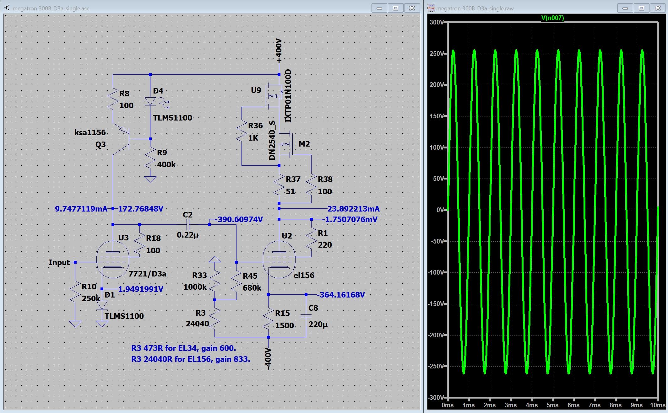
Someone told me D3a is a good tube, Did this in LTspice… Modified Megatron – one less capacitor in signal path and no feedback. Works in LTspice. That's always something.
-
and now for something completely different part 3
JoaMat replied to kevin gilmore's topic in Do It Yourself
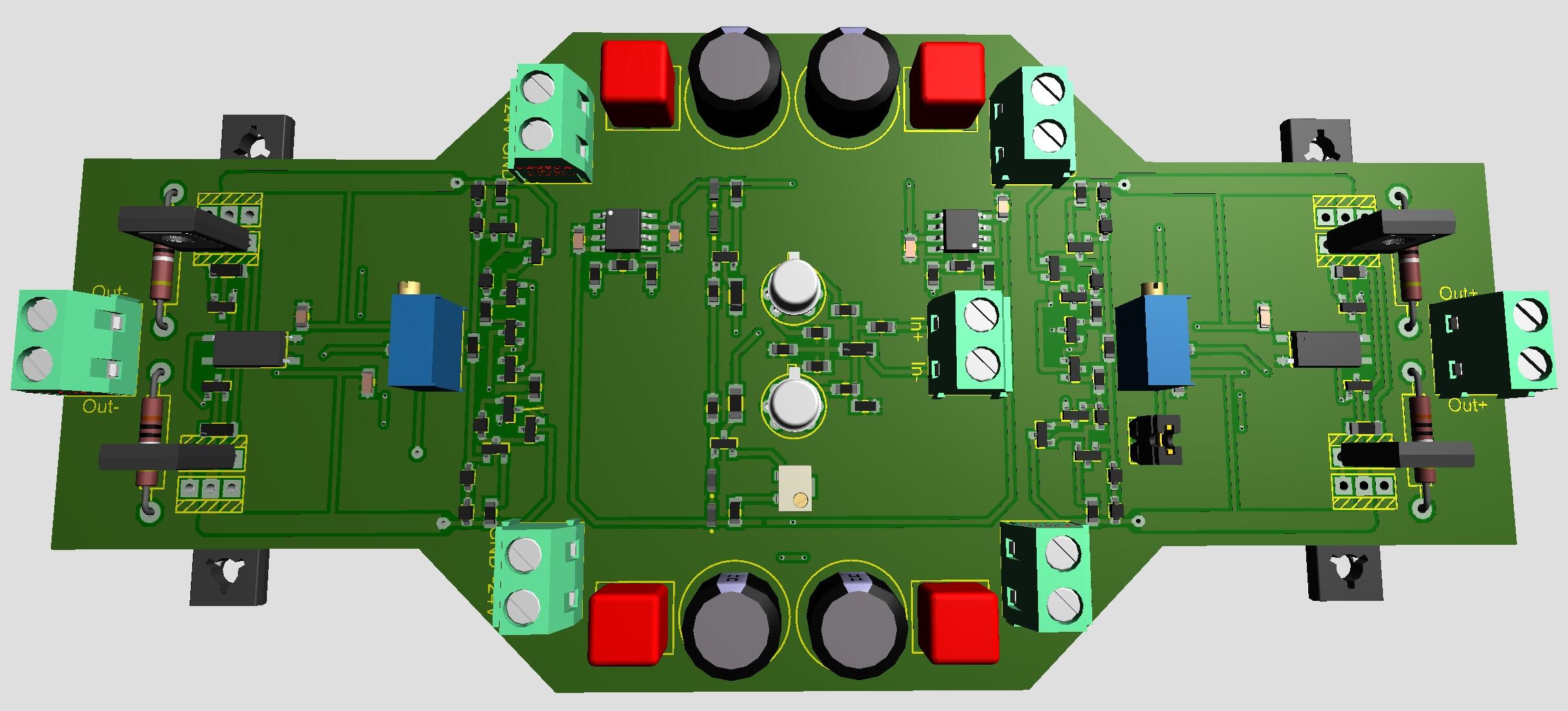
No particular reason behind the jfets, aside I like the to-71 package and that it’s fairly easy to build the layout around them SMD transistors because they are small. I had to decrease current at some locations to reduce heat. I see this amplifier merely as an experiment. I wanted to test if it was possible to make a small board. The bias servo is probably needed while moving from heatsinked MJExxx to small smd transistors. I believe the bias servo previously posted by Kevin, with dual op amps, is preferred. So, another experimental board…
-
and now for something completely different part 3
JoaMat replied to kevin gilmore's topic in Do It Yourself
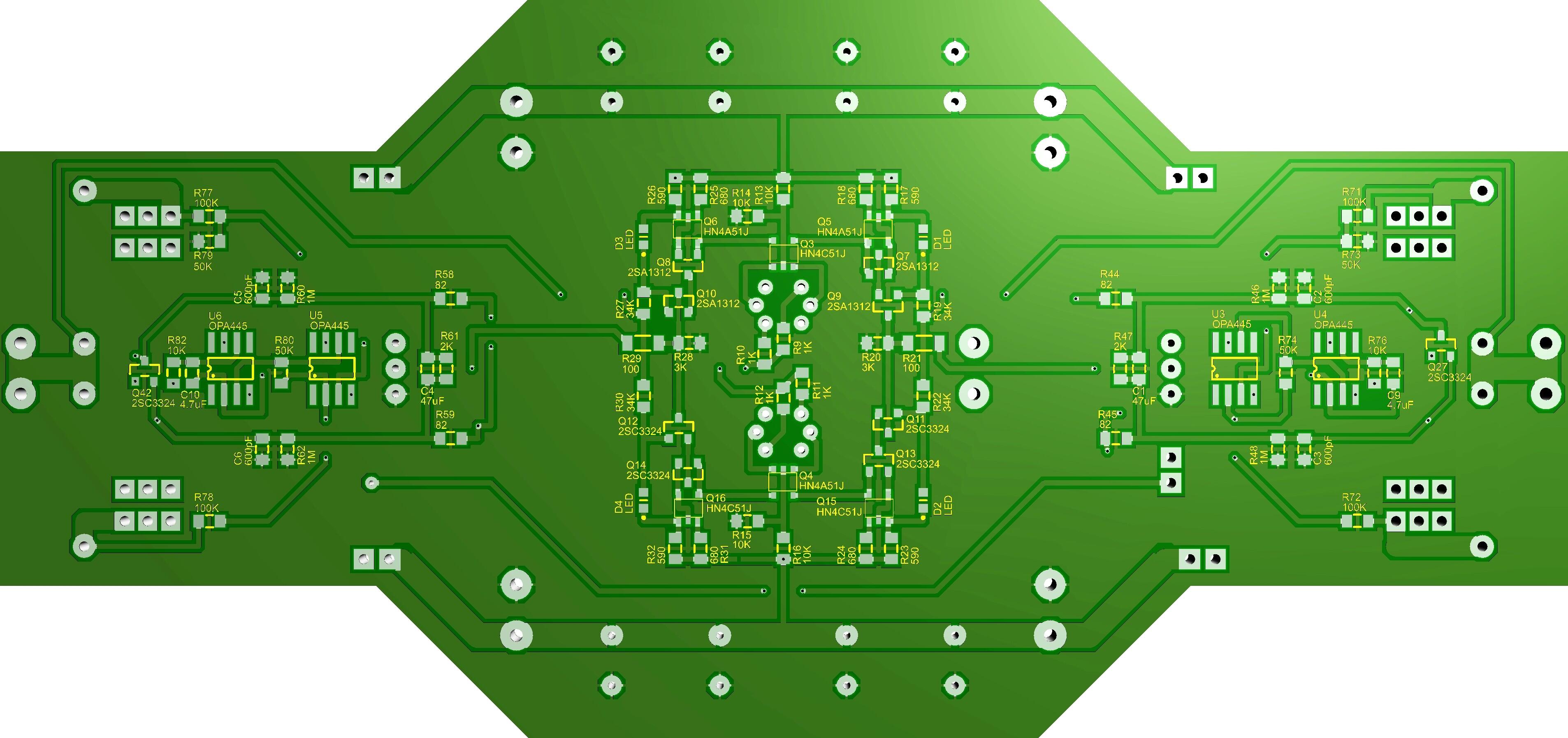
Attached ZIP-file with gerbers, shematics and some 3D views. CFA3smd.zip I’ve used both gerbers when I milled the boards (kitchen made) and that is about three years ago. Board size 160mm x 74mm to fit on Modushop 200mm x 80mm heat sinks. Take a look at the files and see if/how the boards could be a part of your project. I think one should make a few changes to attached gerbers before considering sending them to a fab house. -
Megatron Electrostatic Headphone Amplifier
JoaMat replied to kevin gilmore's topic in Do It Yourself
I tie cathode direct to -HV, -400 V in my case. Works with EL34, 300B, 2A3, EML 20B-V4 and EL156. The datasheet for my Electro-Harmonix 2A3EH Gold says 450 V maximum plate voltage. -
Megatron Electrostatic Headphone Amplifier
JoaMat replied to kevin gilmore's topic in Do It Yourself
Higher gain and in my opinion better frequency response. I haven’t tried other than the 100uF electrolytics. With the capacitors the amplifier is an absolute favorite. -
Happy Birthday!
-
Megatron Electrostatic Headphone Amplifier
JoaMat replied to kevin gilmore's topic in Do It Yourself
I put 100uF/16V electrolytics in those positions in my Megatron with solid state CCS. I think it made a big difference. -
Happy belated Birthday!
-
Thank you everyone. Had a nice one with my wife in our summer(winter)cottage. Now I’m preparing for Boxing Day +6. Birthday of both our children and one grandchild. Happy New Year everyone!
-
Happy Birthday!
-
Megatron Electrostatic Headphone Amplifier
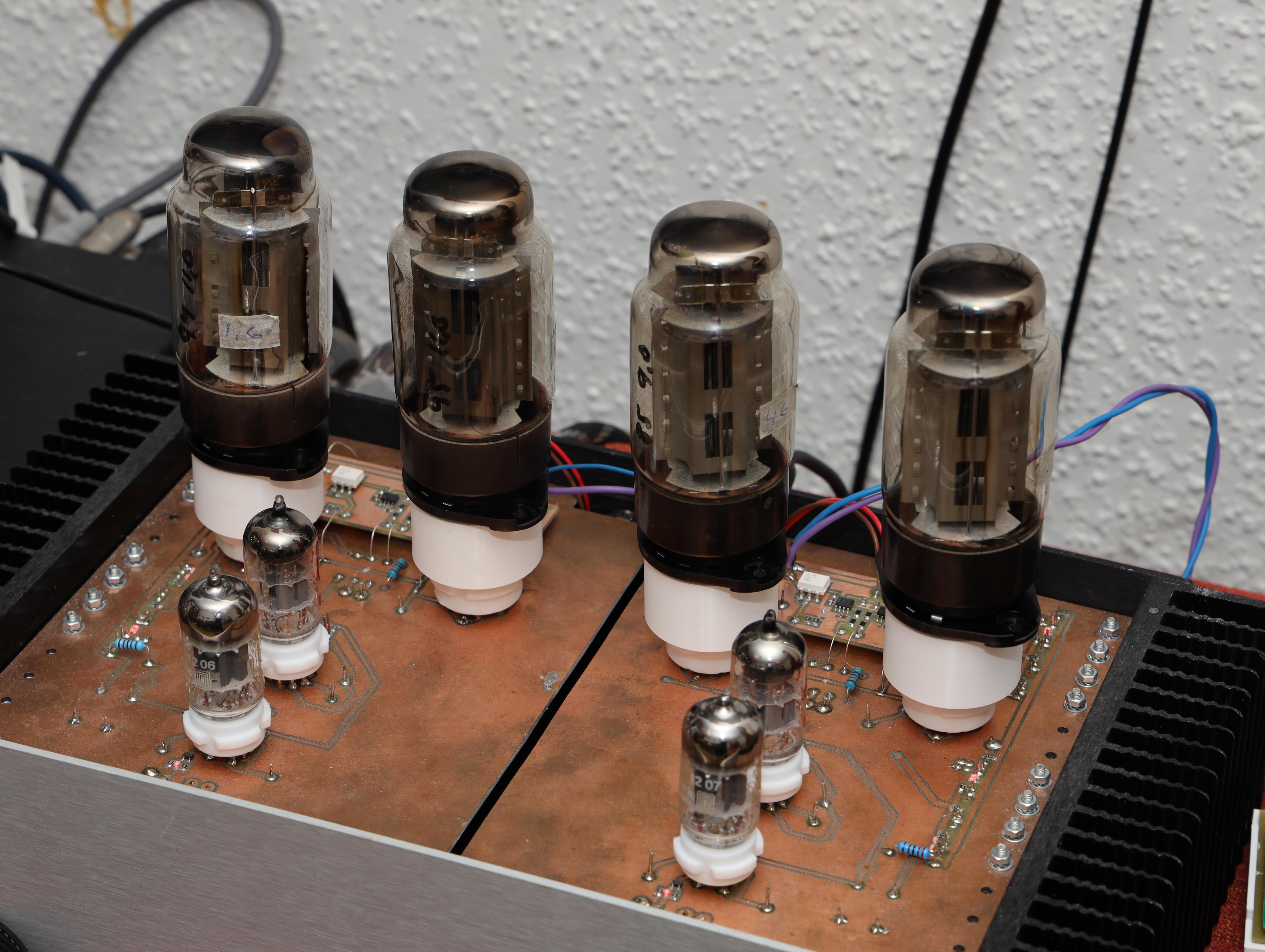
JoaMat replied to kevin gilmore's topic in Do It Yourself
A frendly Head-Caser has kindly lent me four EL156, So, I made myself some EL156 to EL34 adaptors. Here a Megatron SS CCD something with the four EL156. Same friendly fellow has built himself a couple of filament supply for DHT similar to the one in above post.