JoaMat
High Rollers
-
Joined
-
Last visited
Everything posted by JoaMat
-
Happy Birthday!
-
Happy Belated Birthday!
-
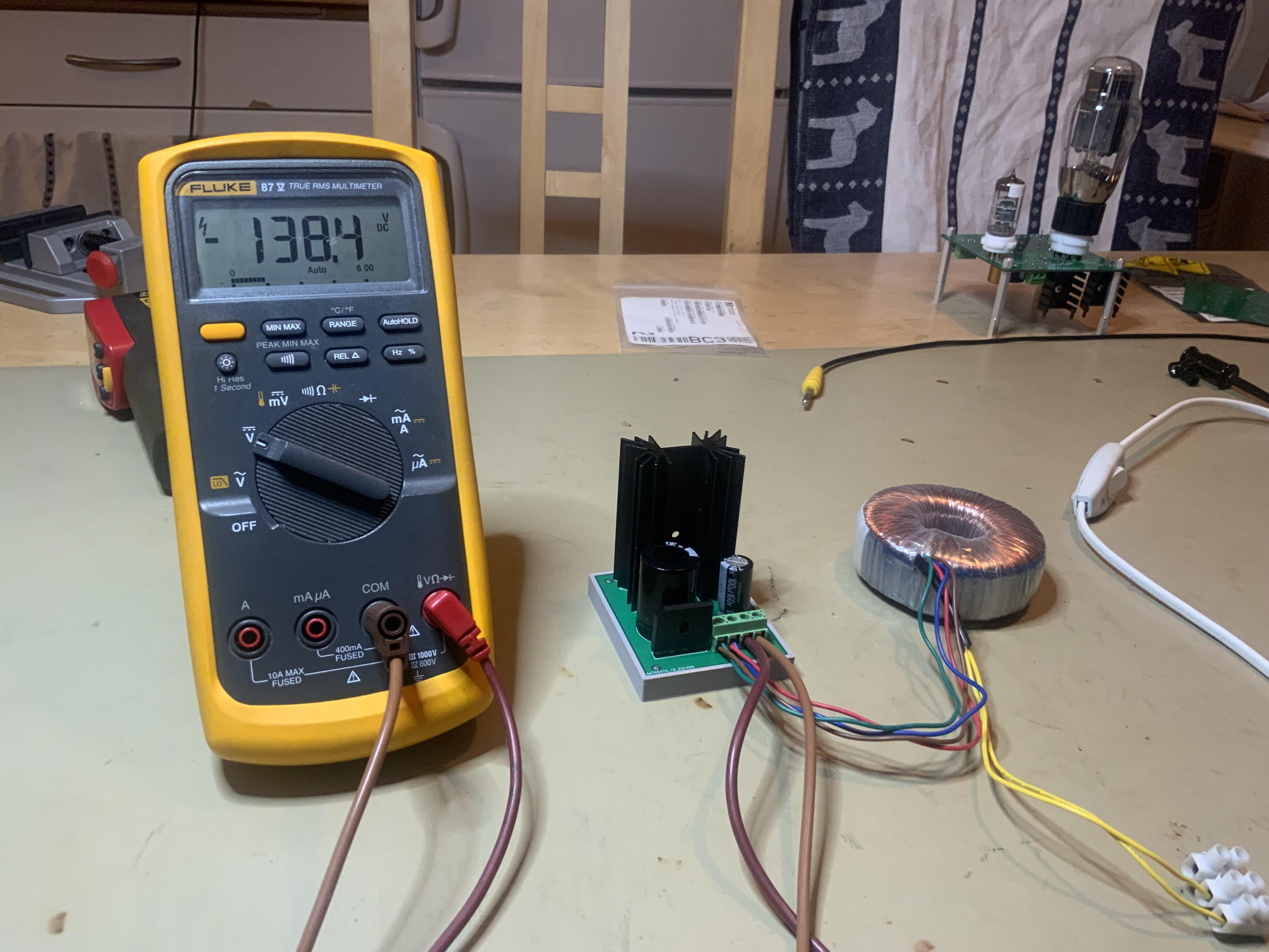
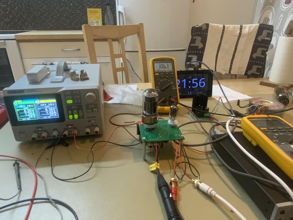
A senior Head Case member sent me two tubes some days ago. An old 6080 and a Westinghouse 12AX7A. Today I completed this in my kitchen. Amplifier is based on Jade, what now that is? PSU as mentioned above is based on Kevin’s GRHV power supply. It has been some fun building days.
-
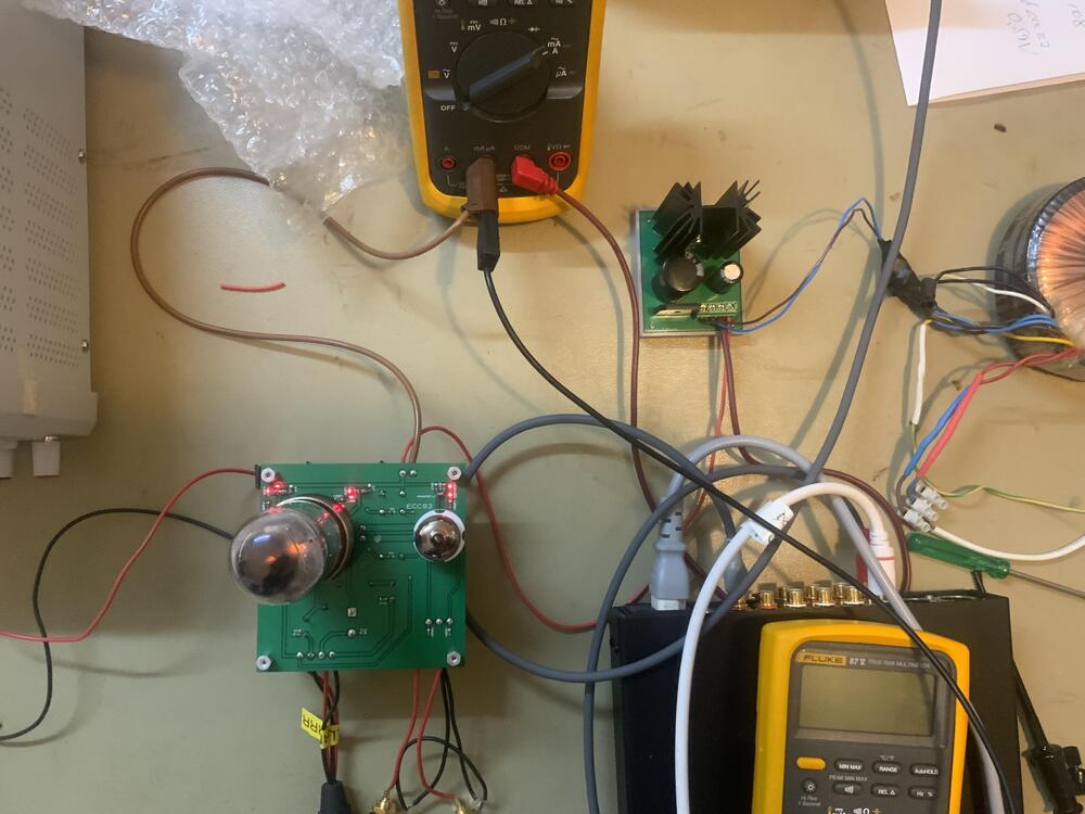
Built a small PSU - GRHV style - for a tube amplifier today. Ops. seems I mixed the test leads -138.4V on the clock. It's supposed to be a positive voltage supply.

-
2sa1413 is to-252 package, isn’t it? How do you solder them in – adapter board? Also, what kind of resistors do you use in the batteries.
-
What transistor do you have for Q16 -Q19 and Q23?
-
Leaving left channel as it is now might be wise. Than you can compare it with the right channel later.
-
Thank you, @jokerman777 Try to do same thing with the right channel. 6,55V and 740V and see what battery potentials and offsets you get.
-
@jokerman777 Well, remote diagnosis isn’t easy. So far, I haven’t had any difficulties to set R42 to 6,55V. Knock on wood. +200V/-548V and +200V/-549 seem somehow all right but can’t you set the voltage of the batteries to 740V. Do you adjust RV1 to set positive battery voltage to +200V?
-
Set R42 voltage to 6.55V with RV2. Set battery voltage to 740V. Same for all for batteries. Do not try to use batteries to zero out offsets. Tell us the offset measurements for all outputs.
-
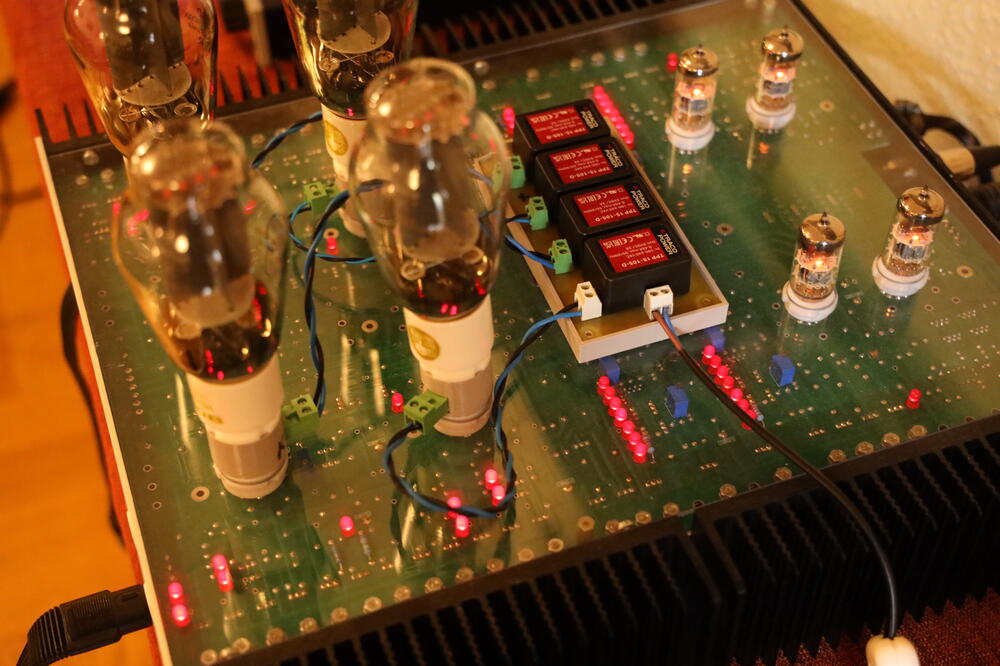
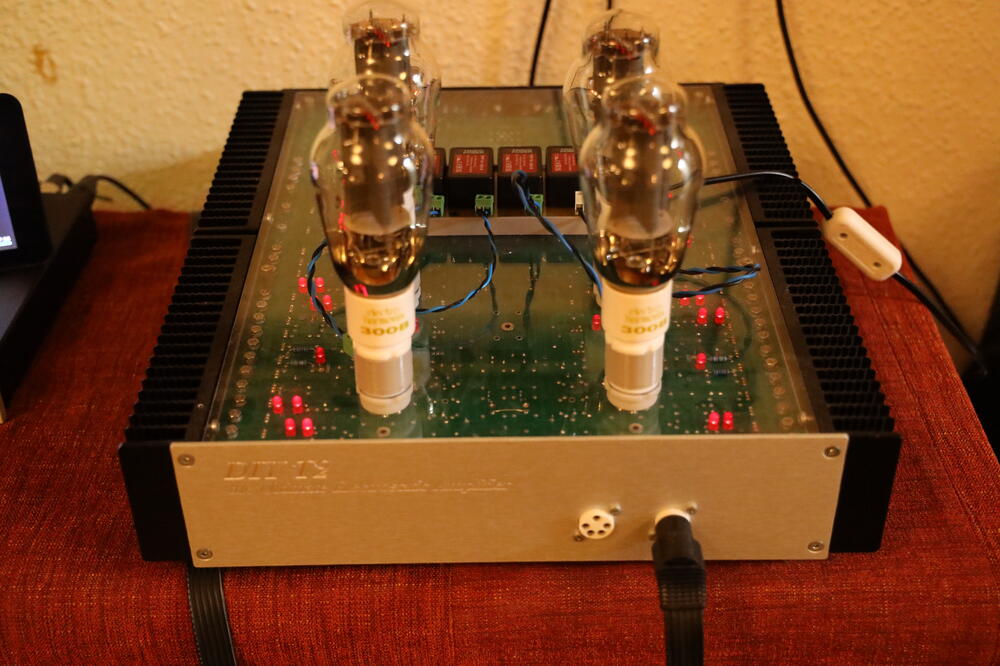
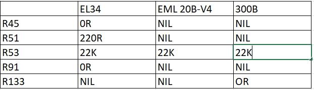
Thanks, simmconn, you are right about R53 and 300B. Table above changed. I’ve no idea of limitation of the output swing. What I know though is that 300B pleases me.
-
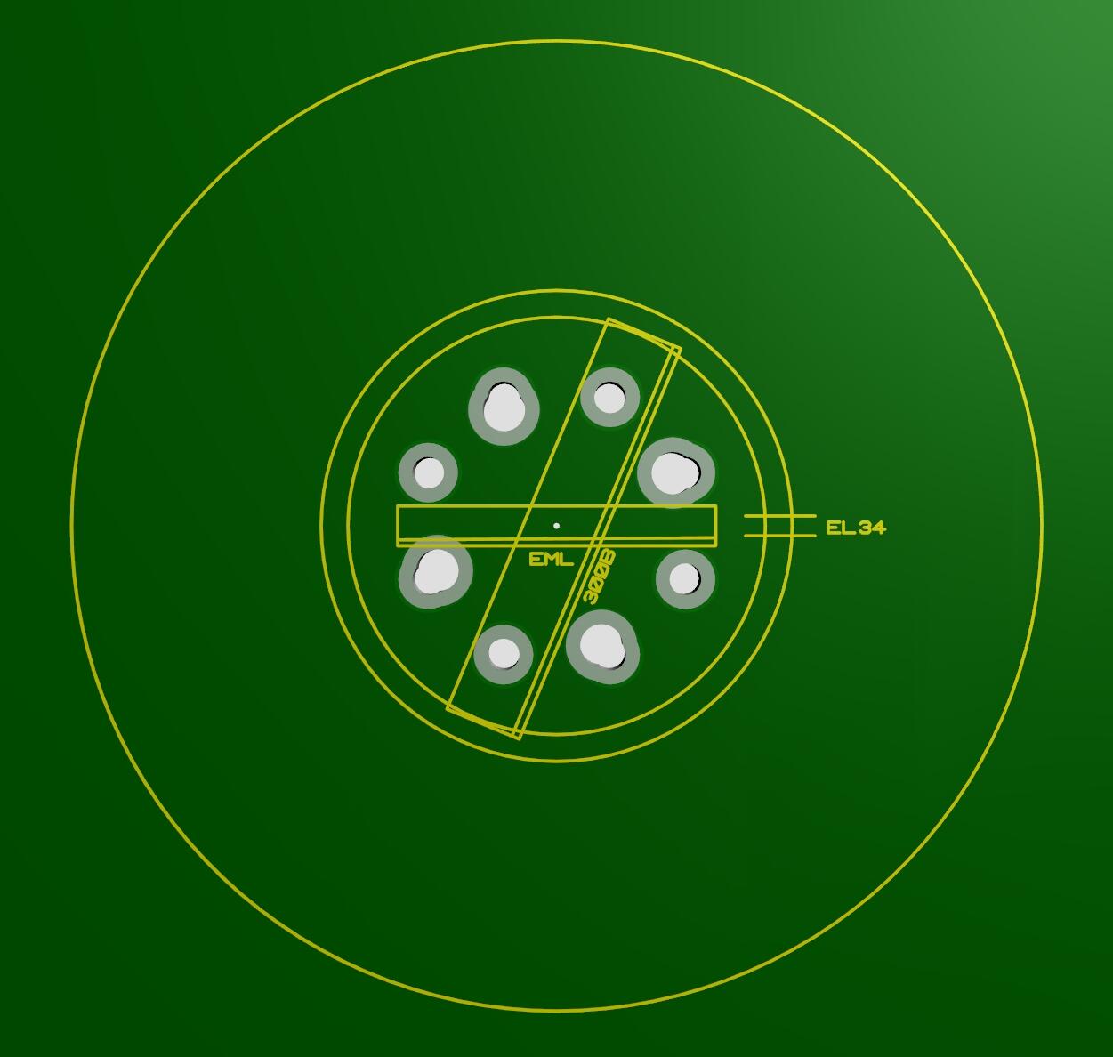
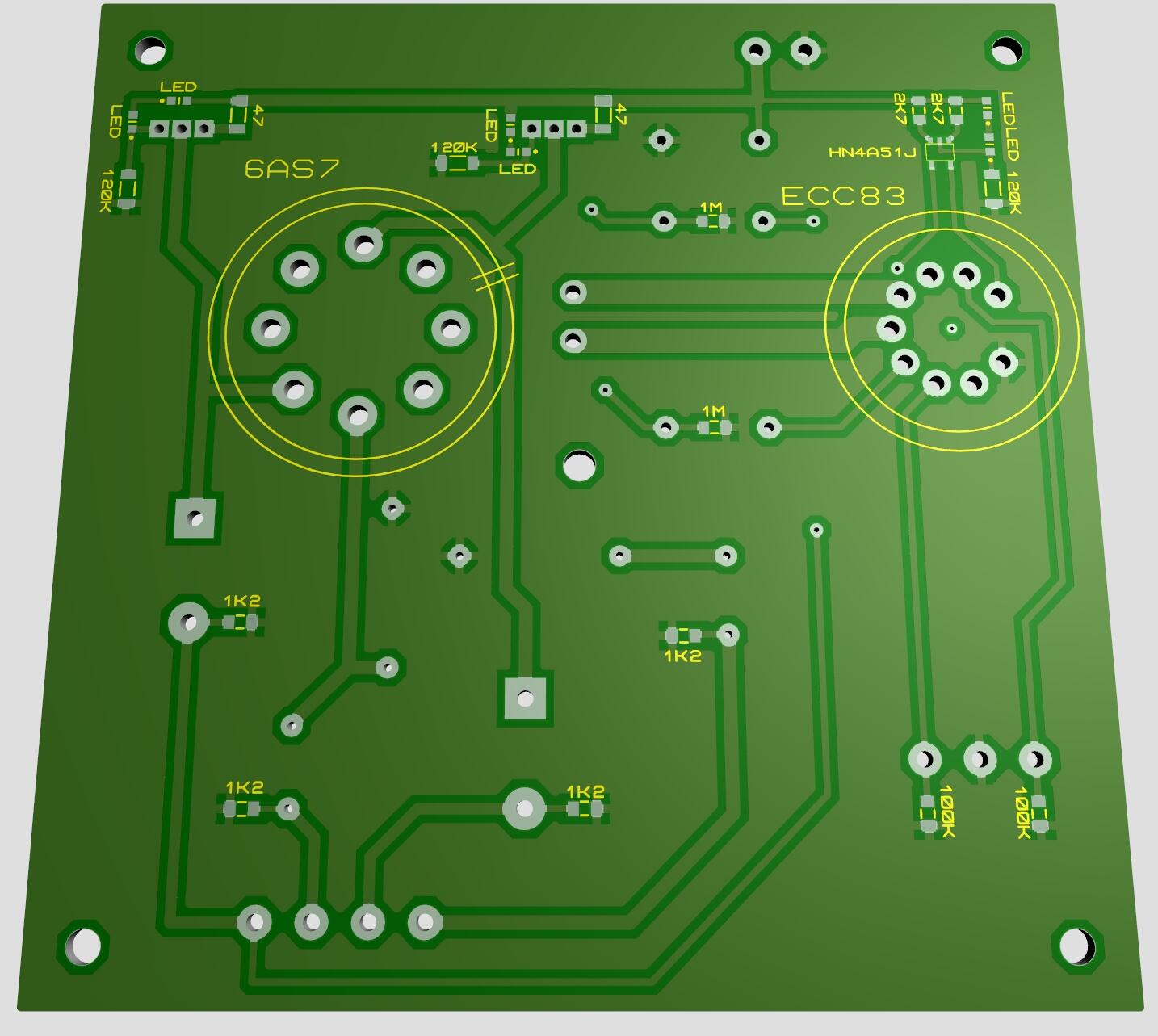
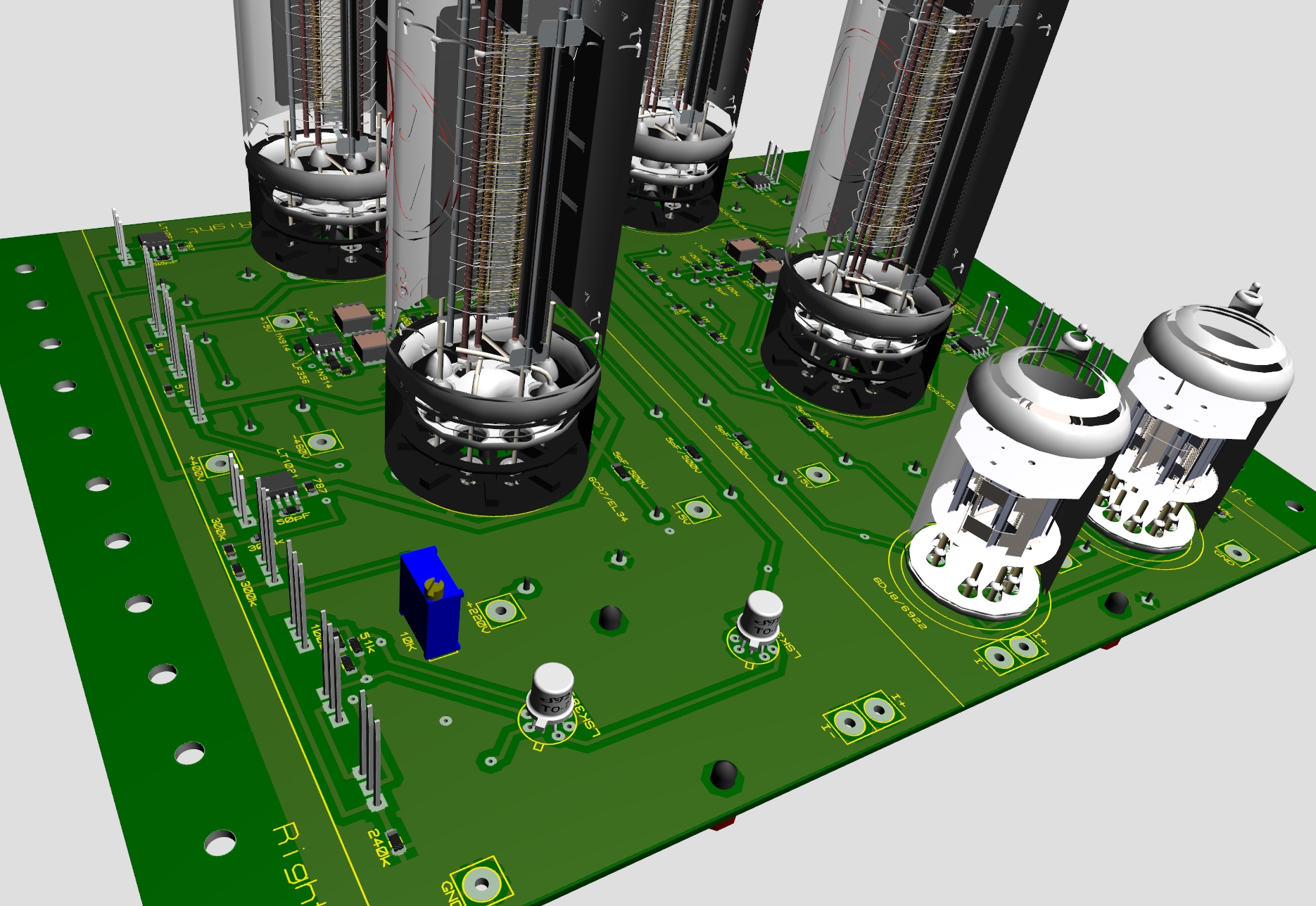
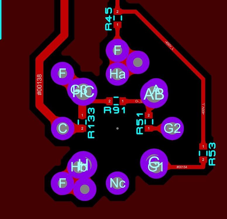
The idea is to populate the five 0805 pads according to the table. disclaimer: if things blow up don't blame me. Edit: Intention is to have a board compatible with the three tube types. When building the amplifier you decide for which tube. So, no "tube type rolling" here. Edit: Table changed.
-
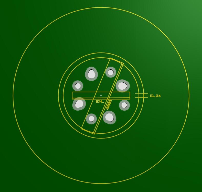
New device package in Proteus. Generic output tube footprint for DIY T2. Accepts EL34, EML 20B-V4 and 300B. Will see if fab house can fix this.
-
Only positive voltage is expected to change. Set voltage cross 22K resistor to 6.5V and don’t change that unless a good reason. Battery voltage of 740V is mostly a good value. But if 748V works be happy.
-
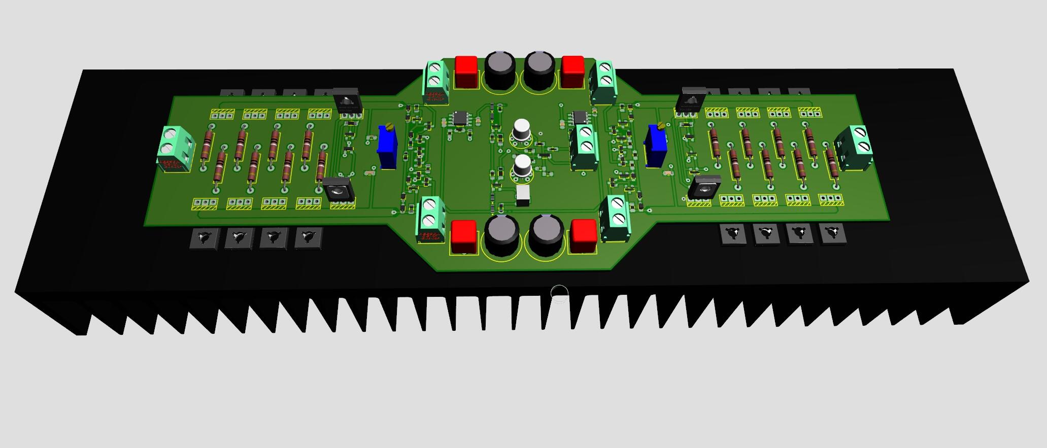
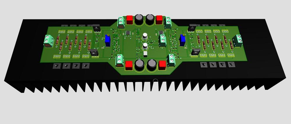
I give up, can’t find a way to significantly shrink it. But this one has four pair output transistor each channel. BIAS servo controlled. Flat on Modushop 300mm x 80 mm heat sink. Project name is CFA3 smd something X4.
-
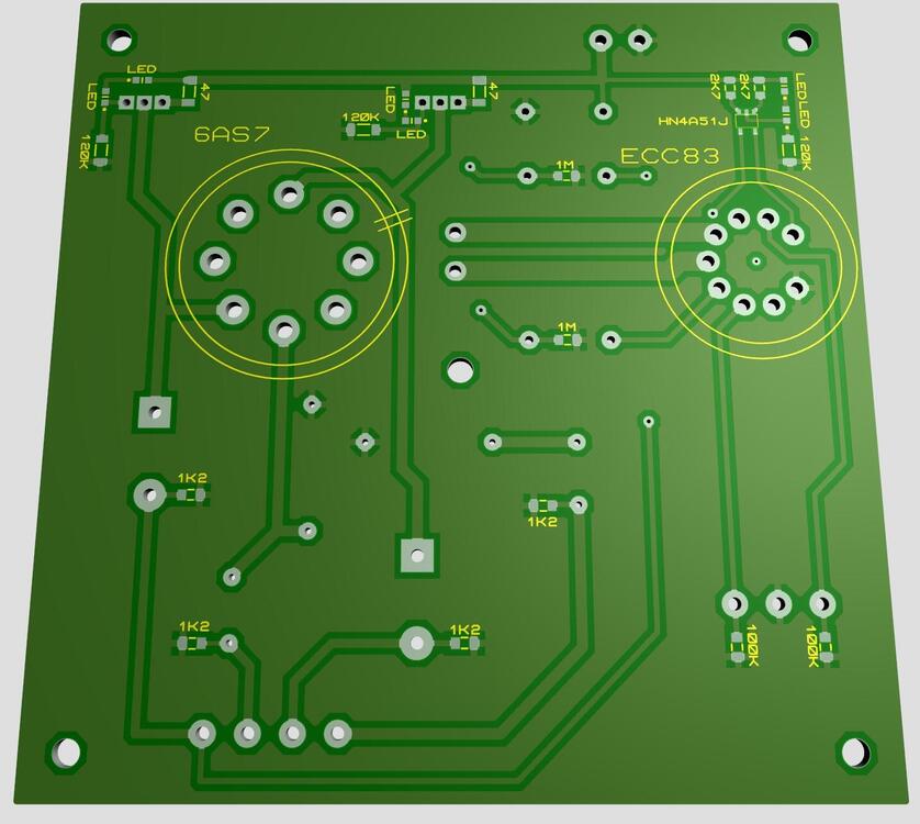
Audiotailor “Jade” something. Current sources, surface mounted components and ordinary films and electrolytics in signal path. Board size just within 100 mm X 100 mm. Then I get 10 boards for only 4.90 dollars. Shipping cost to Sweden is the “heavy” burden.
-
With cpc117n unpowered D1/C4 are put offside and nothing out from Q3 is expected (I think). Power the relay or remove it and see what happens.
-
-
-
look here https://drive.google.com/drive/folders/1r3g2TAtBUaBdiMorTWX7yYgeJ7maQbYW?usp=sharing https://drive.google.com/drive/folders/152thxfZafBmisG0CKCv6X82V-Ch9TjMH?usp=sharing lots of good stuff
-
Run out of k216/j79? Go TTA004B and TTC004B. To my knowledge half a dozen T2 with “modern” components including TTx004B have been built in Sweden and owners/users seem to like them.
-
Great! When the RIP MY T2 was announced, I said to myself - James will have a new T2 ready in 10 to 14 days… Now only three days has elapsed. No rush, James.
-
-
Happy Birthday, Antonio!
-
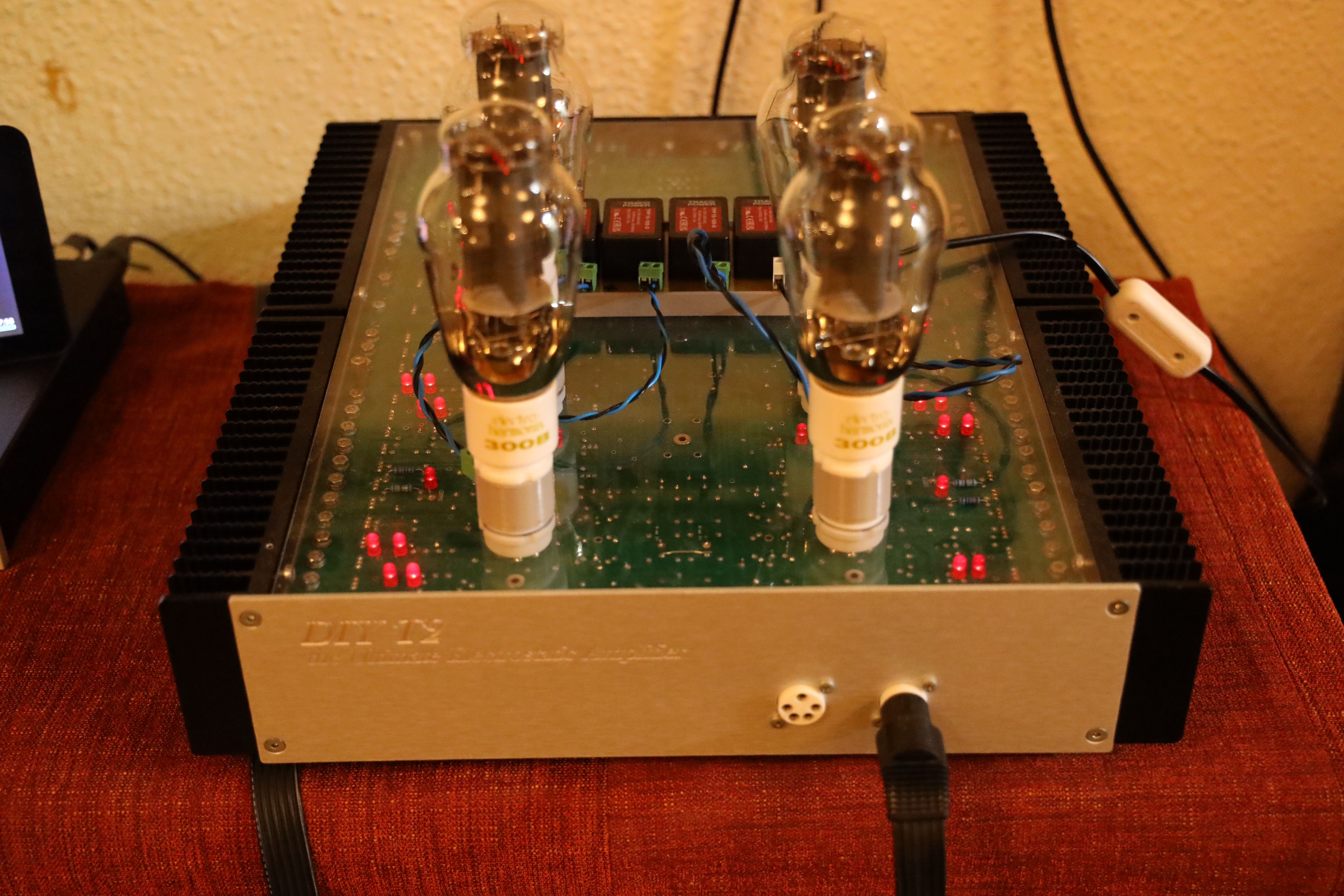
Have used the 300B tubes with DIY T2 for three months now. First two months with an amplifier with all original transistors and the last month with an all-modern transistors’ amplifier. Only issue so far is a failed small solid-state relay in filament supply. Otherwise, I find the DIY T2/300B pleasant.