JoaMat
-
Posts
1,550 -
Joined
-
Last visited
-
Days Won
16
Content Type
Profiles
Forums
Events
Everything posted by JoaMat
-
I’ve been using Denon SC-7000Z for several years and I would say it’s a great tool. With 1.5 mm tip it’s easy to remove a 5 terminal block or a small teflon tube socket. It can also be used as an “hot air gun” and then it’s very practical for desoldering surface mounted components. If interested check Howard Electronic Instruments – I buy spare parts from them.
-

Megatron Electrostatic Headphone Amplifier
JoaMat replied to kevin gilmore's topic in Do It Yourself
Two different types of EL34 in there? -
Electrokit is my favorite supplier – a small and friendly company. Just takes my 15 minutes by car.
-
Happy Birthday!
-
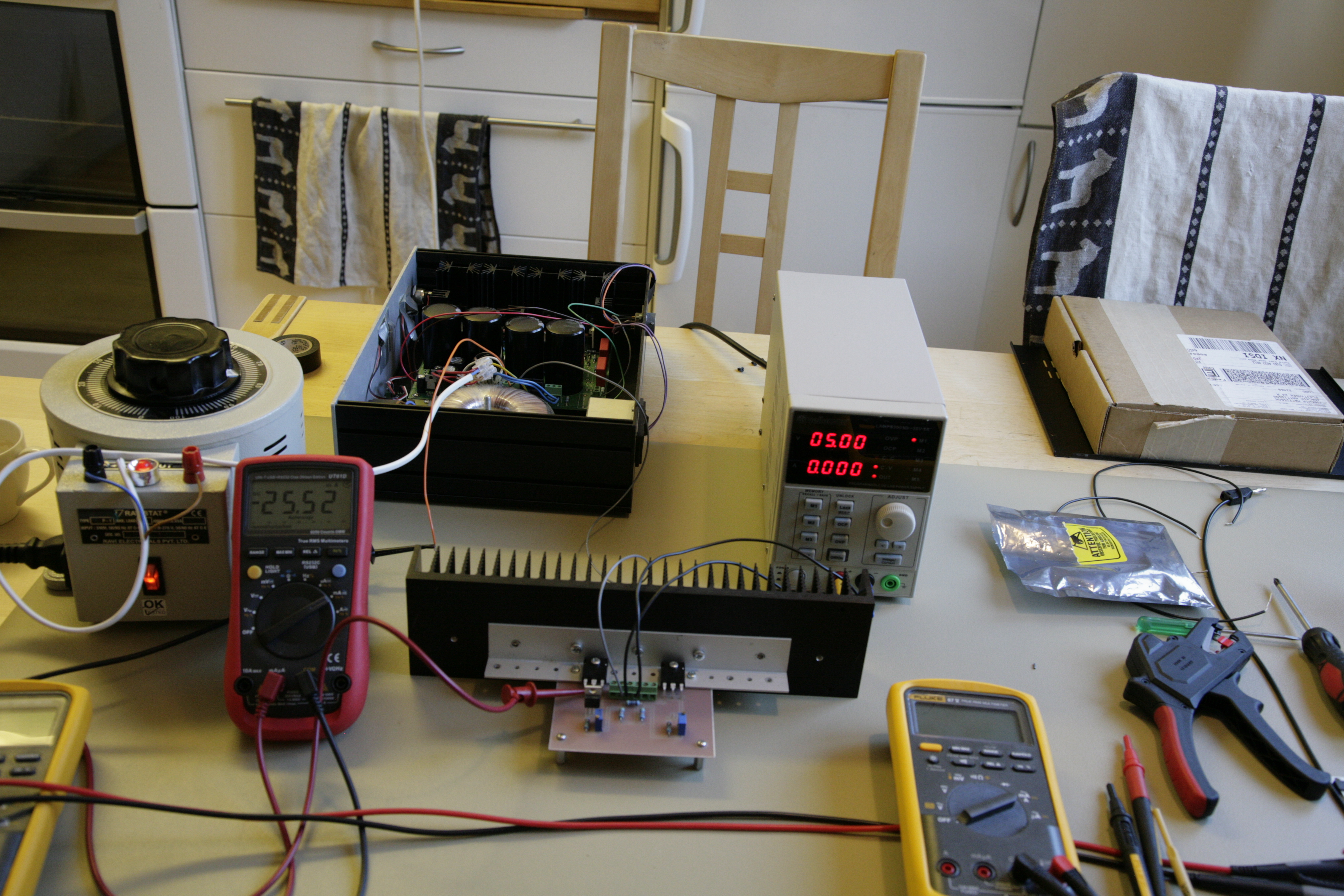
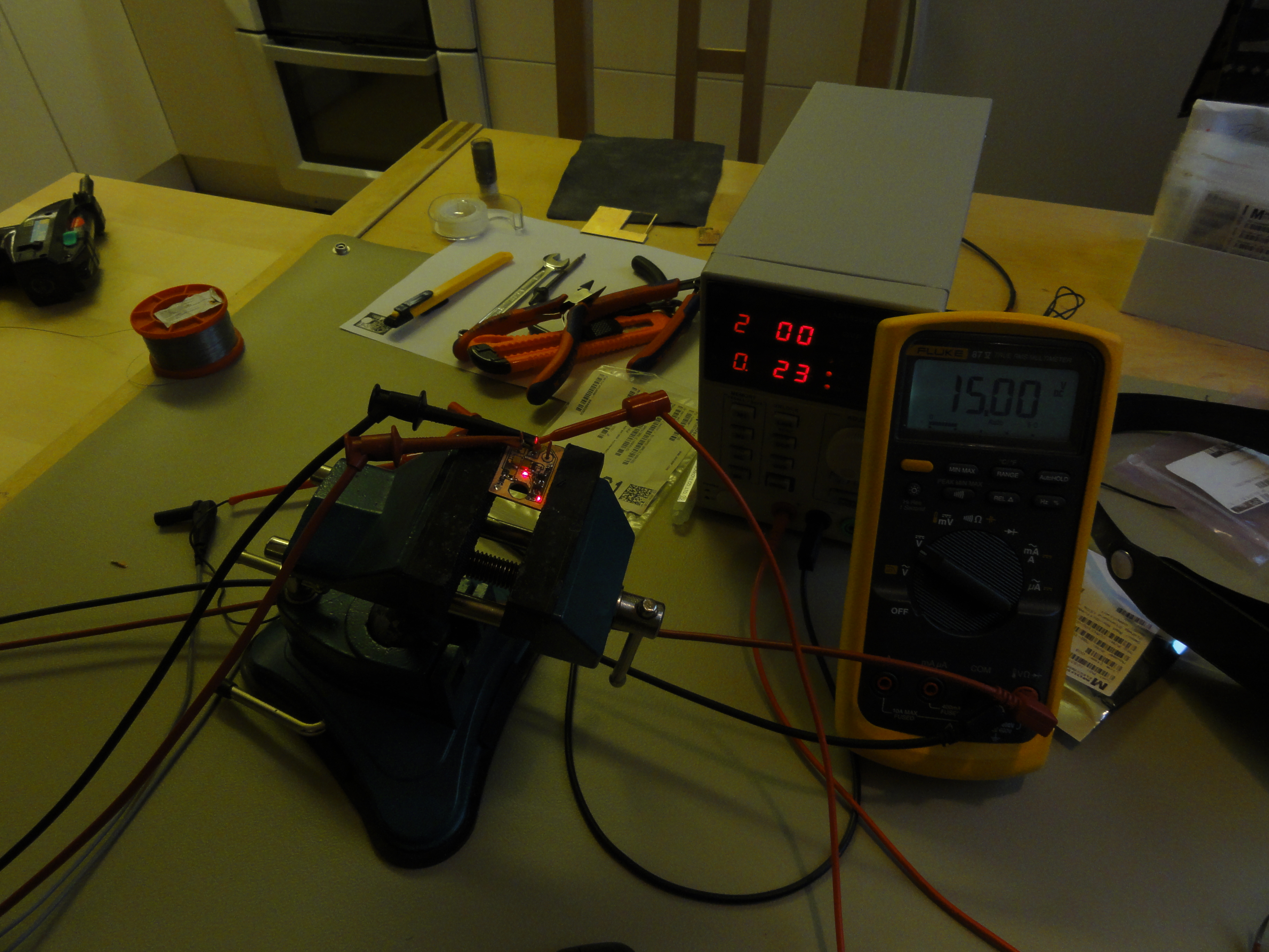
Below is from my kitchen today. I had to test if the DN2540 would do. 25 mA on the meter and voltage, from an old KGSSHV supply, is 887 volts. Only one half of Circlotron and the current seems to stable enough. Might be continued if I don’t break arms and legs during coming week down hill skiing.

- 256 replies
-
- 3
-

-
- Circlotron
- High Voltage
- (and 1 more)
-
My idea with DN2540 instead of “120R resistor” is that you might have better control of the current in the Circlotron. Under normal condition you probably don’t need heat sink with DN2540. 100 V offset should never happen with a good driver but that is in a perfect world. Anyhow, worst case is an offset of +450 V and then the DN2540 is reaching or exceeding its maximum both voltage and power. But I could be all wrong about this.
-
Average temp of 26.7C - can't be better.
-
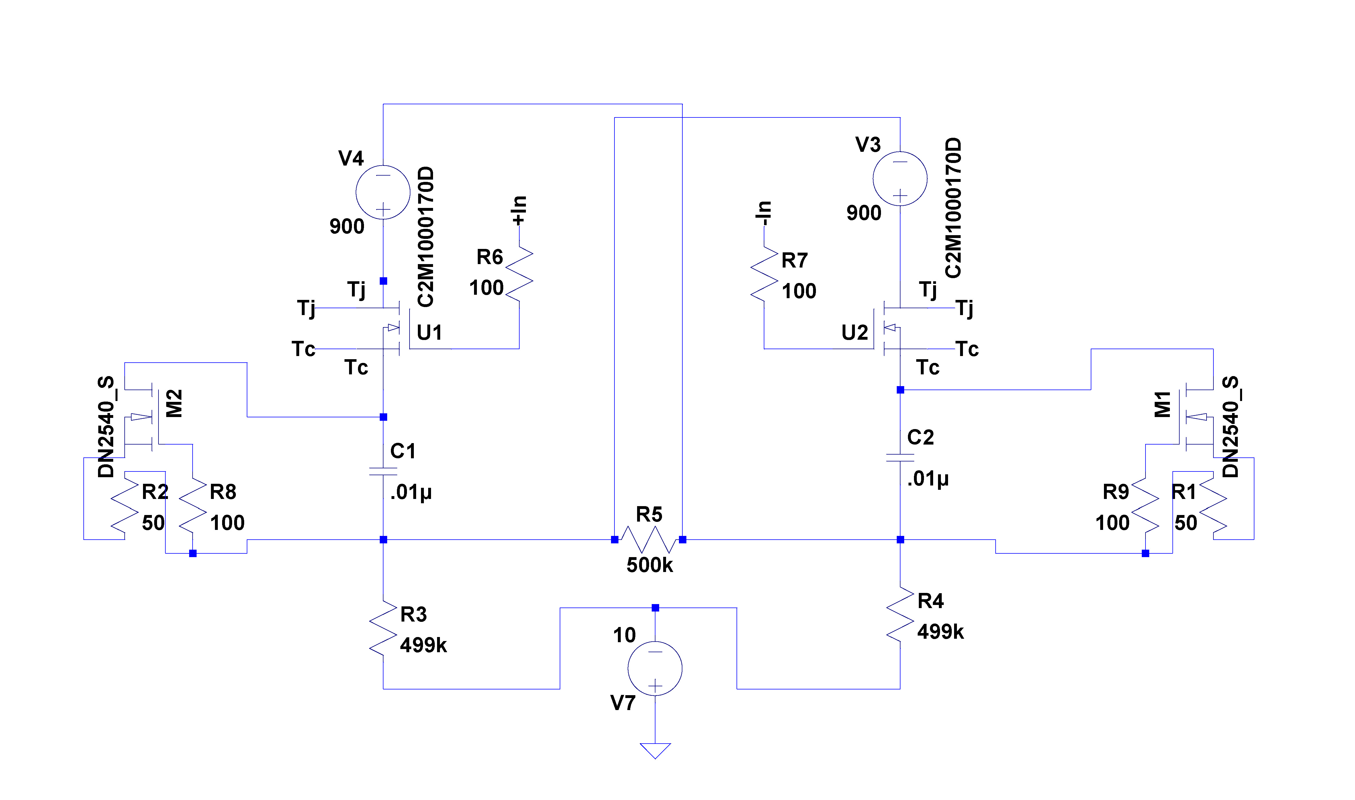
I’ve replaced 120R and optocoupler circuit with a DN2540 circuit. In LTspice it seems to work. If input offset is +100V then I get a current in the Circlotron of 850 mA with the optocoupler and 75 W at 120R resistor and 750 W at the MosFet. With DN2540 the current stays at 25 mA and DN2540 will take some 2.7 W and hopefully nothing will blow. This is of course in theory and what will happen in real life is a completely different story.
- 256 replies
-
- 3
-
-
- Circlotron
- High Voltage
- (and 1 more)
-
What if lower device as DN2540 with C2M1000170D to control current in the Circlotron?
-
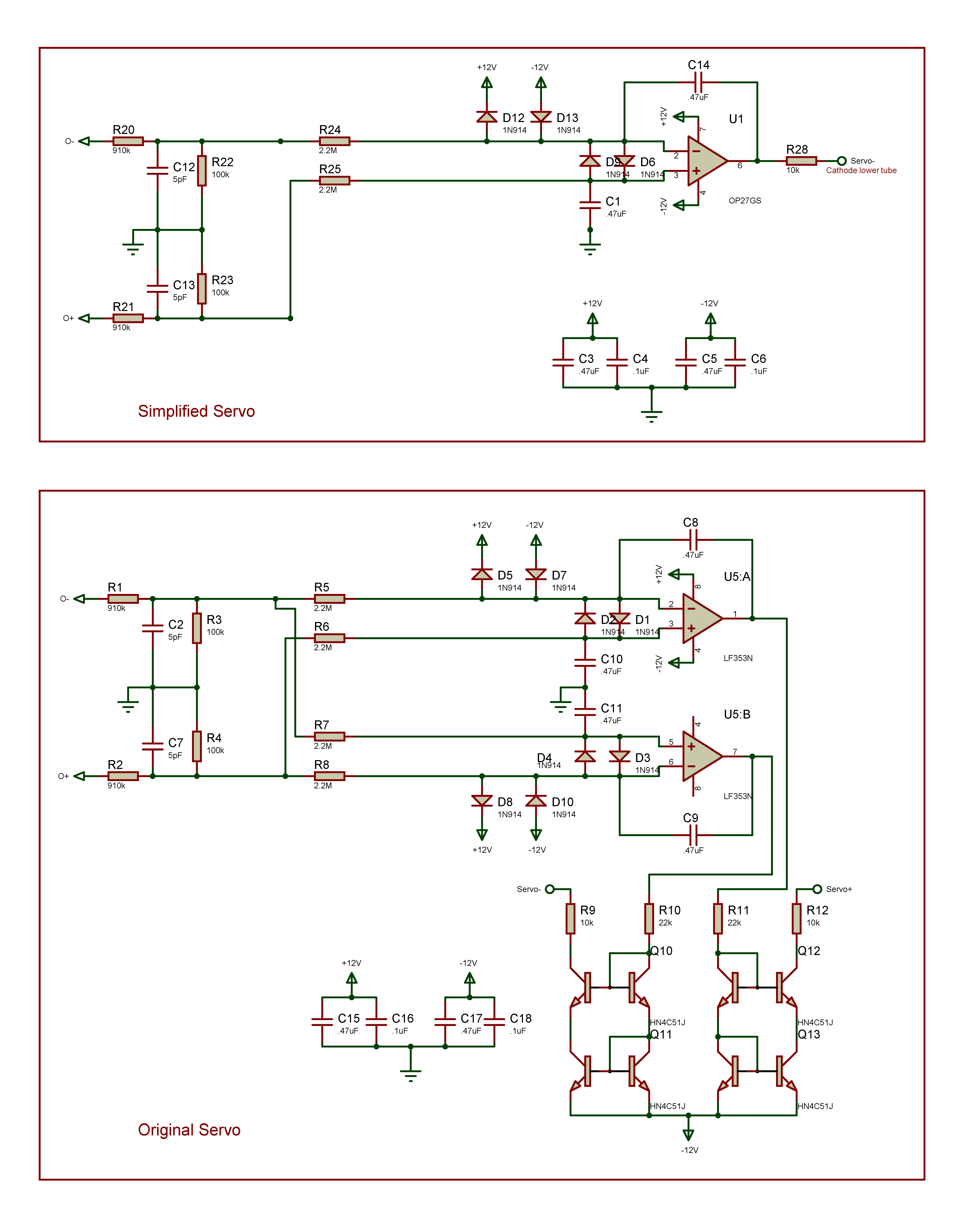
Two months have elapsed. The modifications work alright. Almost forgot what I’ve done. Schematic below shows the difference between the servos.
-
Of course offset servo is not needed with the Blue Hawaii. Blue Hawaii has been around for a long time. Manufactured and sold by HeadAmp Audio Electronics to many satisfied customers. Been given highest possible remarks by professional tester. As DIYer I do feel entitled to do any modifications to any amplifier I like. Doing so with a Blue Hawaii feels like a privilege. I’m very grateful for the Blue Hawaii and can’t thank you the designer enough.
-
I’ve used a couple of different offset servos with a Blue Hawaii. I found them very useful. If you like 45 volts drift you should avoid all kind of servos.
-
Nothing wrong with Servo 2 - the only servo you need.
-
Just finished my morning coffee. Seems to be an interesting day. Thanks a lot Kerry.
-
As I understand LT1021 is used in shunt mode in GRLV. From datasheet I get the impression that the 5 volts version of LT1021 is not meant to be used in shunt mode. As I recall one builder once tried a LT1021-5 in a KGSShvPSU without success.
-
After a second thought I’m beginning to believe that it shouldn’t make any difference at all. After the diodes the “output” should be the same after swapping the leads from transformer, or?
- 256 replies
-
- 1
-
-
- Circlotron
- High Voltage
- (and 1 more)
-
Thanks. This is a very long shot but what happens to the hum if you swap one of the AC from transformer to rectifier diodes (HV900). Will there be a change in hum if the AC to the two “rectifier bridges” are in 0 degree or 180 degree phase?
-
Isn’t that an earlier PSU version with the long zener string?
-
LTspice indicates a need of another 3 V unregulated. Plus more diode switching noise. Still a golden reference device or is it a silver line thing?
-
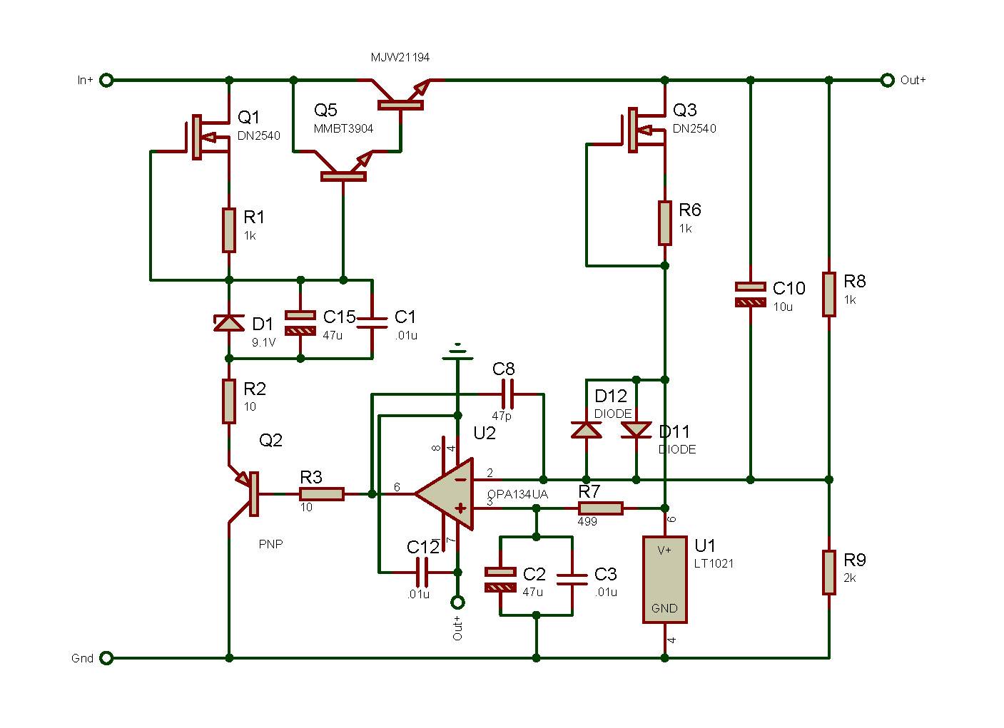
Thinking loud. What if a simple CCS north of the 9 volt Zener as below? Will certainly make a tiny smd version layout looking cleaner.
-
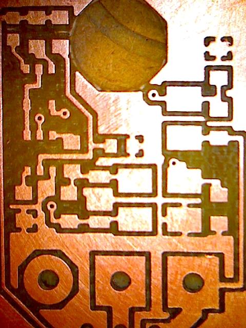
Milled this today – negative regulator. Shot by USB camera approximately magnitude 20. Using a 15th end mill, minimum clearance between pads, traces etc. is 16th. There are 5 vias 12th and they actually hit the bottom pads quite accurate. CNC machine is a fantastic gadget
- 813 replies
-
- 10
-
-
Did this today. Positive golden reference regulator. I managed to make a Kerry device in my kitchen but I think he is pushing the envelope now. I’ll try to make negative regulator as well and if this succeeds I’ll put them in a T2 PSU. Dark picture so you can see the small red LEDs on the board. Hope the small GRLV hit the market soon.
-
Great work! Reason for KST42/92 replacing PBSS4140DPN? - need for higher collector-emitter voltage?
-
470R resistor, isn’t that the grid resistor? If so, is 2 W really necessary? From simulation I get some 2 – 4 mA through the resistor. In my Grounded Grid with mostly surface mounted devices I use 0805 chip as 470R - 1/8W and they seem to work.
-
Law of nature. You always need a sufficient transformer.