


JoaMat
High Rollers
-
Joined
-
Last visited
Everything posted by JoaMat
-
Oops. Schematic posted above uses 2sa1486 in the current tunnel – my first boards had the 2sa1486. Schematic in the link uses twin ksa1156 in the tunnel and the boards have the twin ksa1156. The boards Micheal and Jose have had made are created from the linked schematic.
-
Ajaj! That -400V is something from earlier schematics I worked with and I obviously forgot to remove it. The -400 V potential is created by voltage divider R53 – 56. Otherwise the schematics are identical except for that components have different coordinates (I hope, crossing fingers). Thanks for noting it, Steve.
-
You can use +/-450V for +400V and -460V. But I suggest you find a good way to achieve +220V.
-
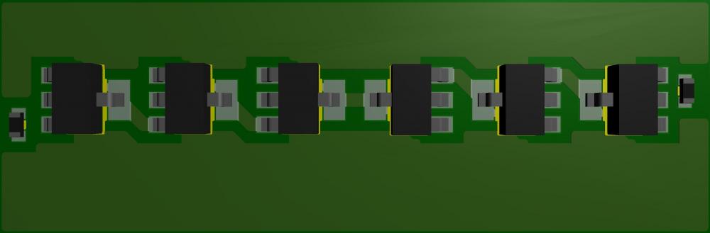
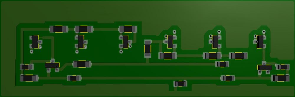
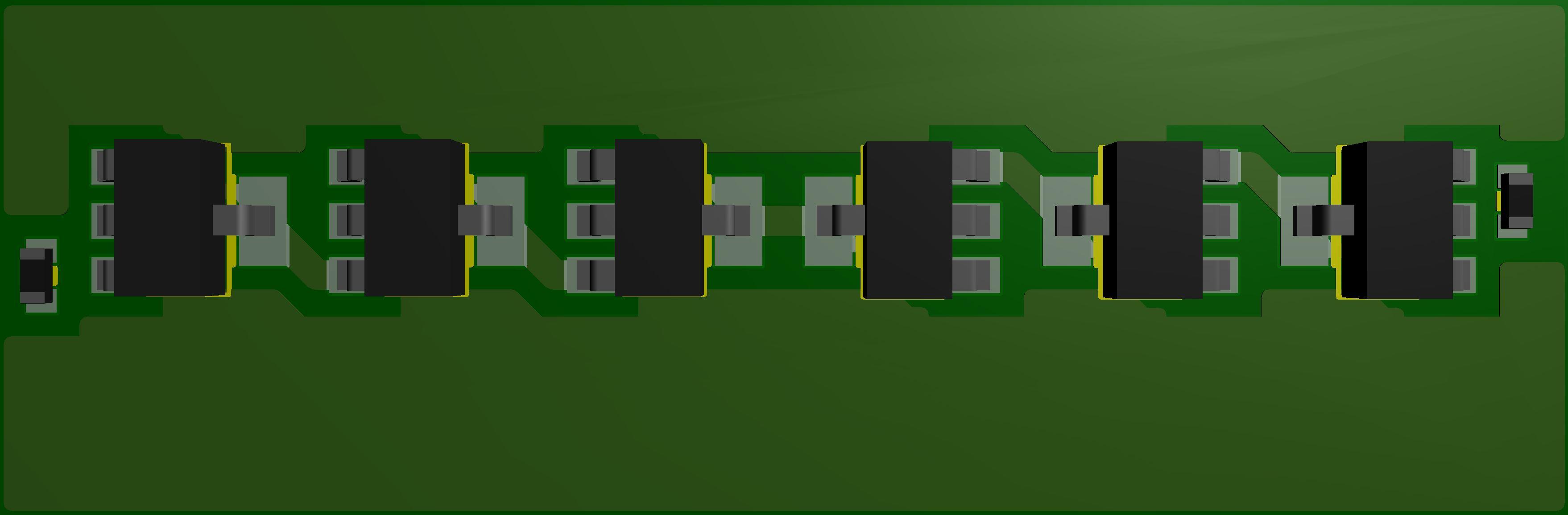
Oh! I forgot Kerry’s micro GR - that would really be something. LinkWell, I changed the voltages as said above on a T2 PSU that is a bit different from the original. I used those lower voltages for my T2 for some time before I built mini T2 and it worked great. So if you dare to lower the voltages on your T2 PSU and remove the 7812 and 7912 and put in the https://www.amb.org/audio/sigma78_sigma79/ set to 15 volts. Then you have an universal PSU. I haven't tried AMB sigma78/79 in T2 PSU but someone has to...???I’m using a modified T2 power supply. +250V reduced to +220V. +/-500V and -560V are reduced to +/-400V and -460V. +/-12V increased to +/-15V. Filaments as original. But the -400V is not used at all with this amplifier.A very early layout attempt. Have to figure out how to spread the parts. Board size 2.65in x 0.87in.
 Increasing trimmers resistance always increase corresponding side’s current and vice versa. If upper trimmer (ksa1156) increases corresponding side’s output voltage increases and the other decreases. If lower trimmer (ksc2752) increases corresponding side’s output voltage decreases and other side increases. So far I’ve preadjusted all eight trimmers to the same resistance. Resulting in roughly the same current of all for channels and in an output voltage of some positive volts - all good and not needing any further action. To me it has been a bit tricky to turn all trimmers to achieve better balance and offset than when the preadjusted.OK, now I’ve reached further. Replaced all eight 2K resistors with 2K trimmers. Makes it easier to change the current. Set at 1.6K current start at 2.5 mA and climbs to 4.5 mA. IMO it’s still an interesting amplifier and I believe it’s possible to build an all SMD version.
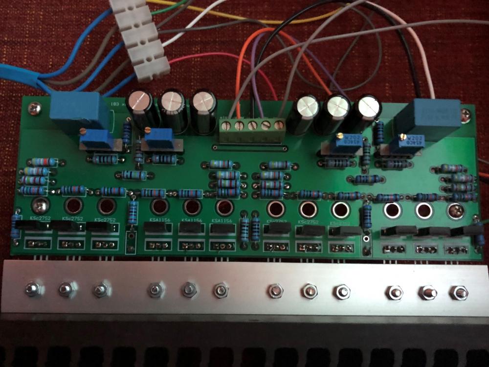 Reduced the 2k resistors at base of input transistors by 100 ohms steps. 1.7k give approximately 7.5 mA and I have decided to keep it there until further…Thanks folks. No matching. I use our kitchen table as workbench and to avoid some nasty conflicts with wife….Nice! and thanks for files.Modushop heat sink 300 mm X 80 mm and Modushop Galaxy Maggiorato front and back panels. I buy them as spare parts. Brackets and aluminium plates for top and bottom I get from a local shop. I've drilled and tapped M4 holes at both ends of heat sinks to fasten the panels. Below is a board attached to 200 mm X 80 mm heat sink - temperature stabilazed at about 50 degrees Celsius. With 300 mm heat sink temperature stabilized at 42 degees. Current stabilized at 20 mA with resistors as silk screen.
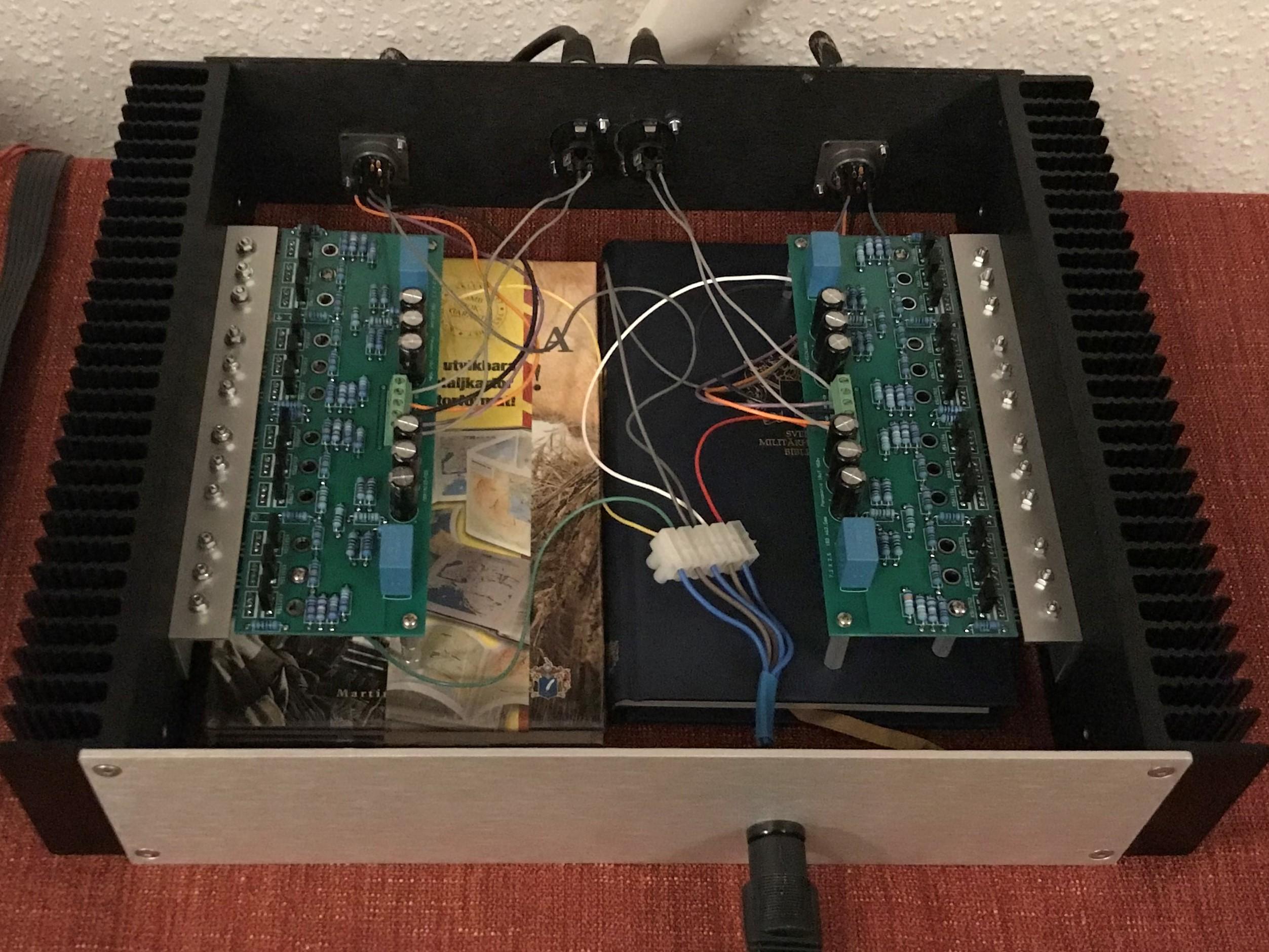
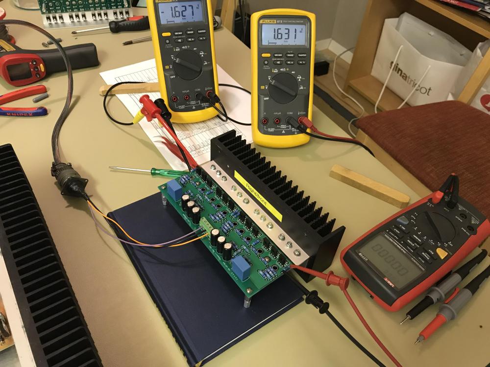 Amplifier built on Gary’s (congo5) boards. I really like this one . Cheap and easy to build - and it sounds really good.
 More Sort Guld. A Søren built amplifier is easily recognized. Very nice!!Nice work indeed. I like the two box approach. The transformers – are they DIY made?Maybe one could change resistors on Alexey’s board to achieve -20 V.Happy Thanksgiving!I don't remember, but capacity is 3.3Ah when new. How much is the current of the mini?Found this in closet. I guess it’s some kind of charger I built a couple of years ago. Six Mean Wells and charger regulators and each cell has his own charger. Red light will probably turn green when fully charged. I don't remember but I will see in a couple of hours.
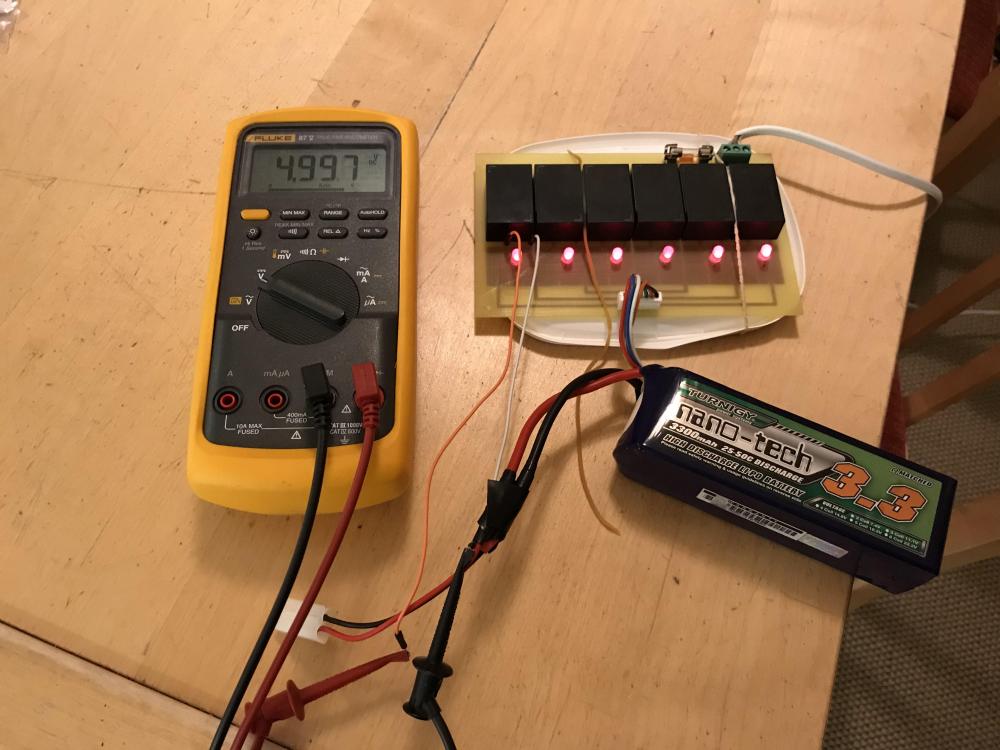 I used the battery pack summer 2016. LiPo 6 cells, one pack each rail, give you some 22 volts reduced by the regulator. Those LiPo packs are used by RC people. I bought from hobbyking.com.


Important Information
By using this site, you agree to our Terms of Use.
Account
Navigation
Search
Configure browser push notifications
Chrome (Android)
- Tap the lock icon next to the address bar.
- Tap Permissions → Notifications.
- Adjust your preference.
Chrome (Desktop)
- Click the padlock icon in the address bar.
- Select Site settings.
- Find Notifications and adjust your preference.
Safari (iOS 16.4+)
- Ensure the site is installed via Add to Home Screen.
- Open Settings App → Notifications.
- Find your app name and adjust your preference.
Safari (macOS)
- Go to Safari → Preferences.
- Click the Websites tab.
- Select Notifications in the sidebar.
- Find this website and adjust your preference.
Edge (Android)
- Tap the lock icon next to the address bar.
- Tap Permissions.
- Find Notifications and adjust your preference.
Edge (Desktop)
- Click the padlock icon in the address bar.
- Click Permissions for this site.
- Find Notifications and adjust your preference.
Firefox (Android)
- Go to Settings → Site permissions.
- Tap Notifications.
- Find this site in the list and adjust your preference.
Firefox (Desktop)
- Open Firefox Settings.
- Search for Notifications.
- Find this site in the list and adjust your preference.