


JoaMat
High Rollers
-
Joined
-
Last visited
Everything posted by JoaMat
-
See below.

-
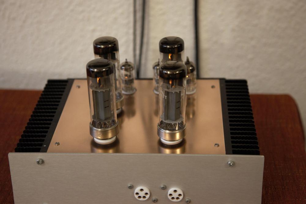
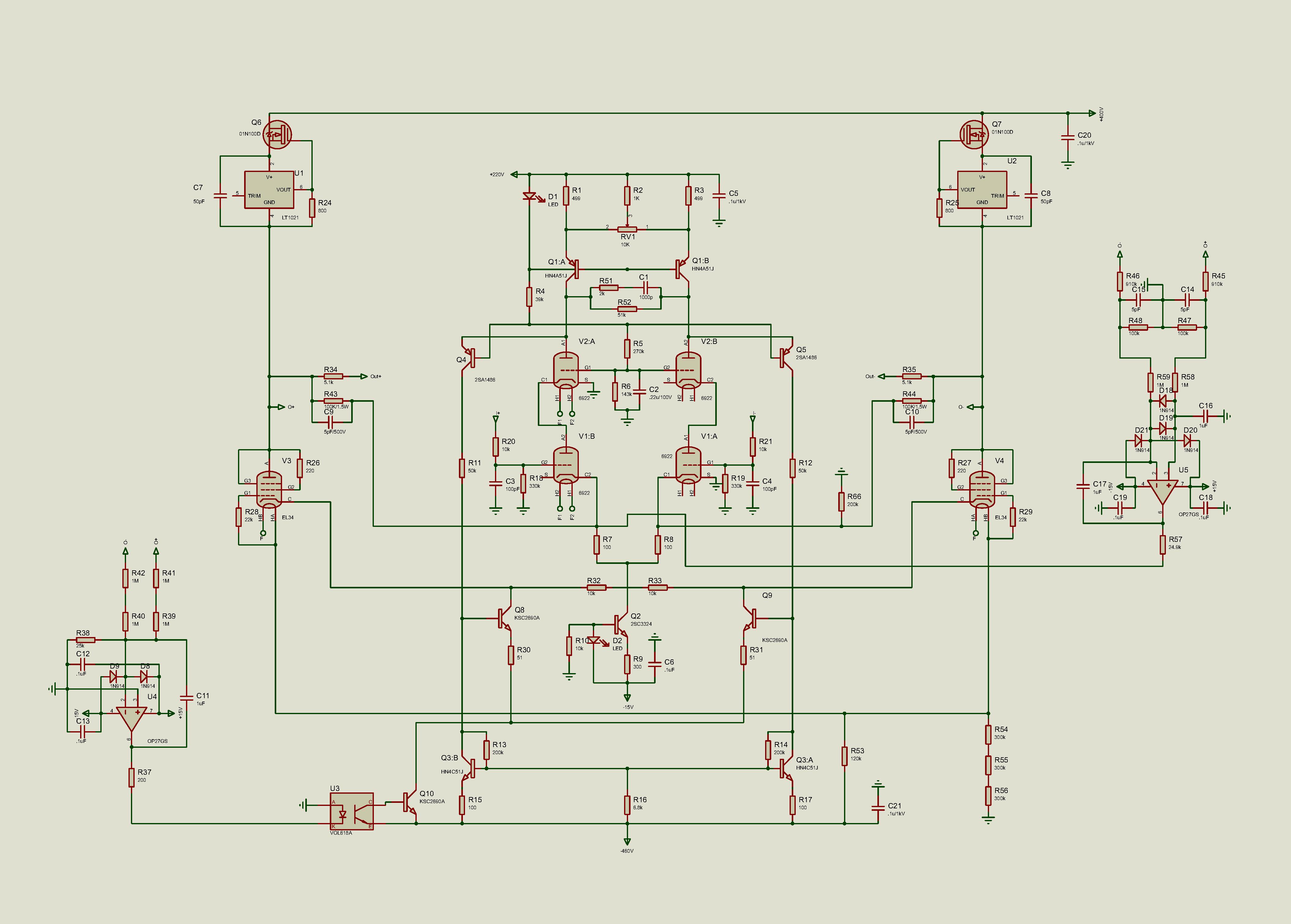
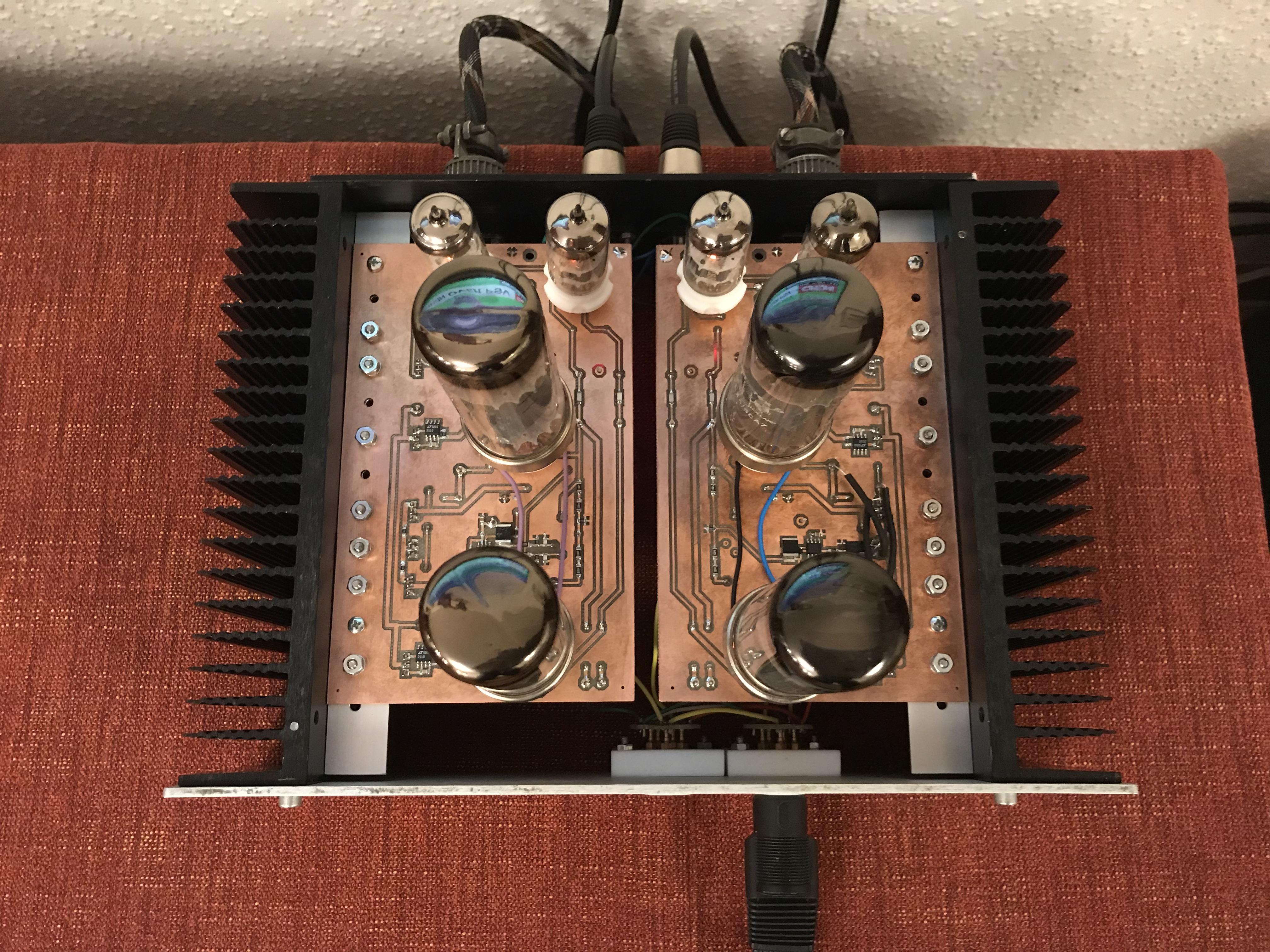
I’m sorry, but - I will not compare my, in kitchen made, amplifier with the famous DIY T2. One way to compare… well, build one – it’s fun. Schematic above.Have been listen to the new amplifier with EML 20B v4 tubes for a couple of days. Since 20B pinout and heater voltage differs from EL34 I use adapters. Maybe it’s about time to make a board dedicated for the Emission Labs tubes. The tubes looks amazing and have printing on the glass. In this early stage layout the printing and the front of the tubes are facing the listener. I found the big tube 3D model (300b) at grabcad.com, done by Andrew Whitham, United Kingdom.
 I am very satisfied with the outcome of this build. Some background. I wanted to build an amplifier based on the T2 but simpler. There isn’t anything I’ve invented. I just copied and pasted pieces and ideas from Kevin, Kerry, Birgir et al - without asking for permission. Draw up a schematic this morning of the amplifier in the same “fashion” as DIY T2 by Kevin Gilmore. The amplifier doesn’t have R66, which is suggested by Kevin. Be aware of errors since I did this in a rush. As about the sound. I AM VERY HAPPY with her. But that’s maybe like asking me how much I love my four grandchildren.
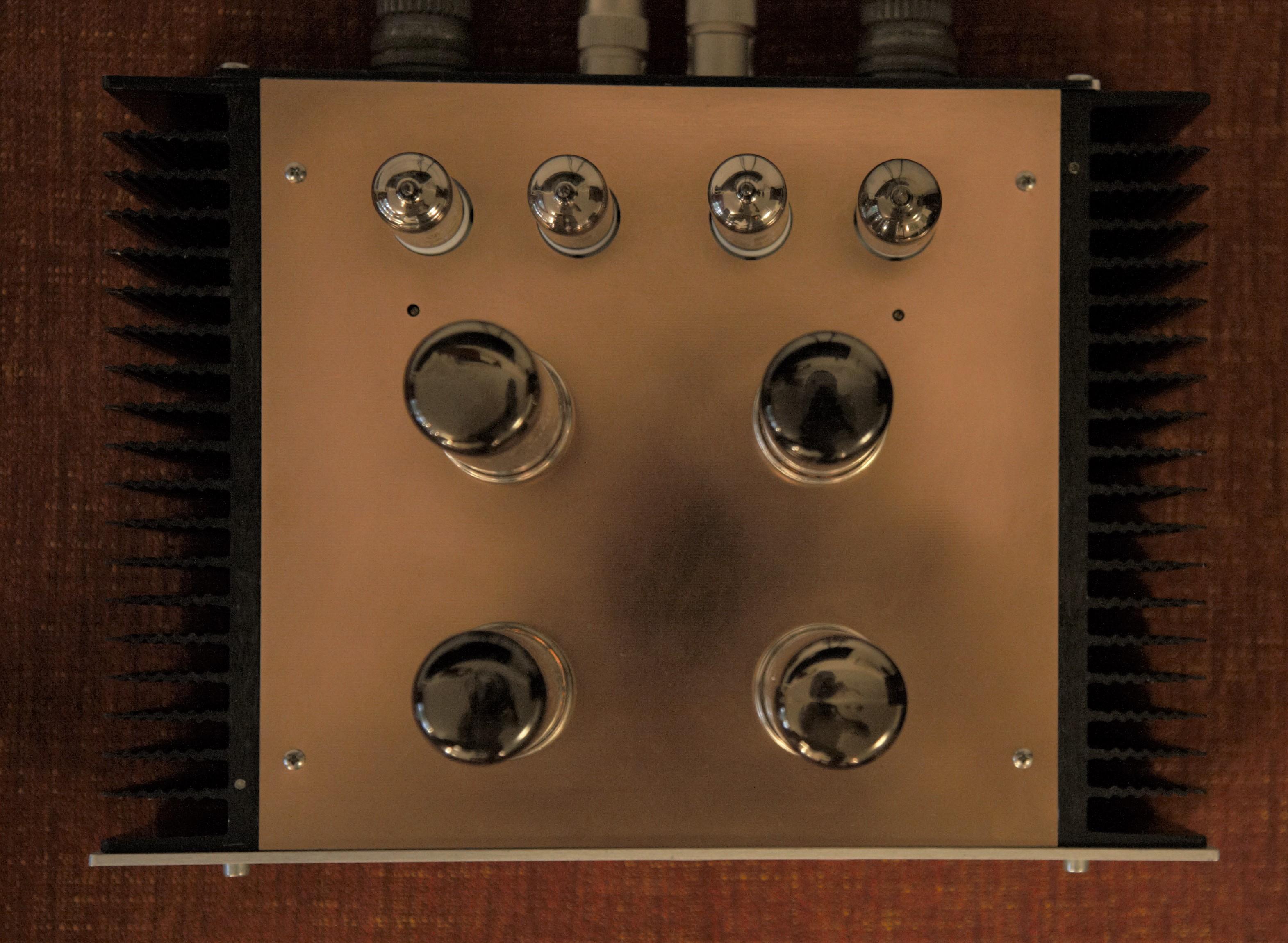
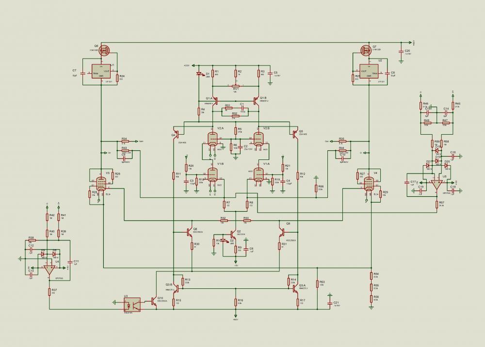 Now with top plate. Aerial view, the two holes in front of outer small tubes are for balance trimmers. Adjust balance after some time of warm up and then insert jumpers for the servos.
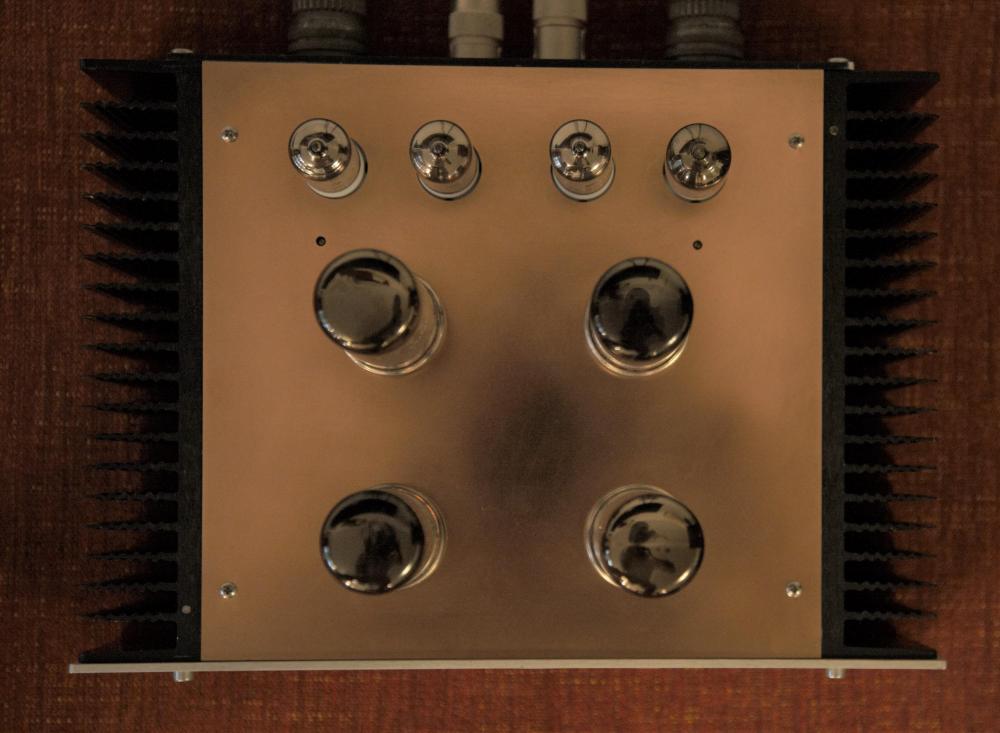
 but, but, nothing in the tubes - must be vacuum tubes……….. Looks absolutely beautiful. Very interesting with the modules.Heard him twice alive. Not at Madison though, but fortunate there is this recording.
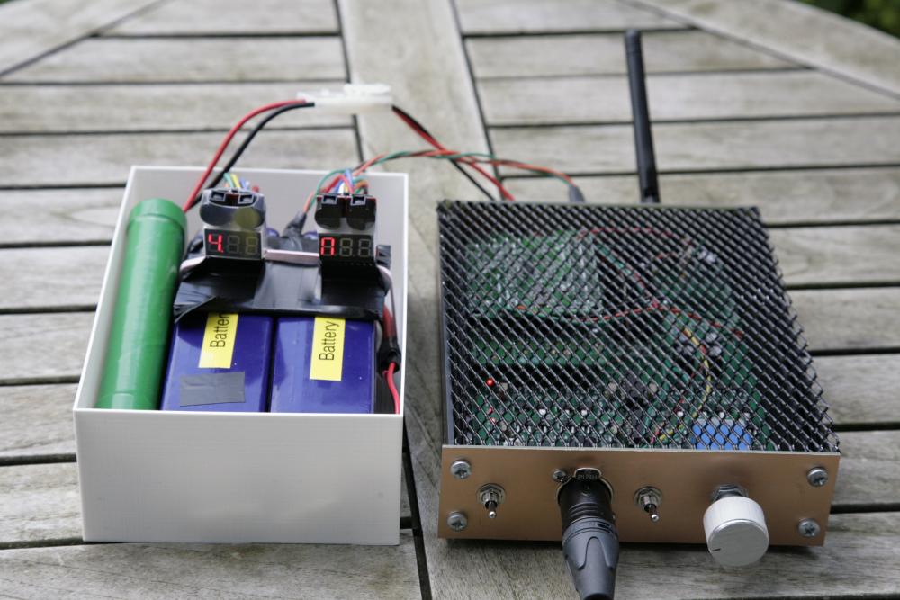
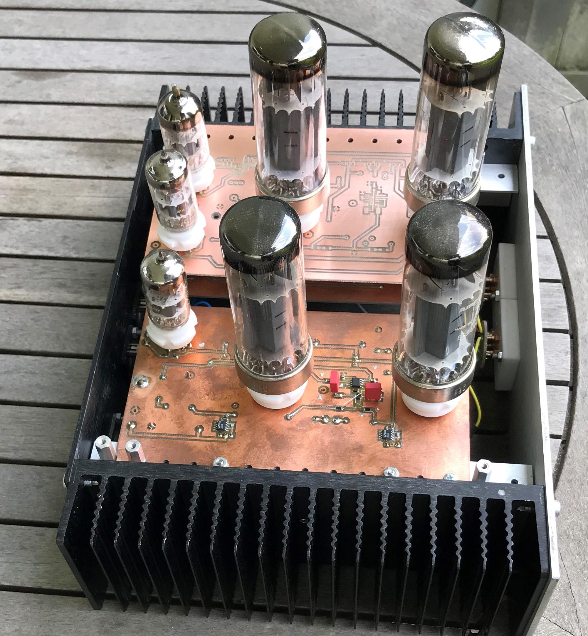
 Now with left channel. The work with left channel went very smooth – no errors – like plug and play. Need a top plate, fix that tomorrow. And a matching PSU… but now I need some vacation.
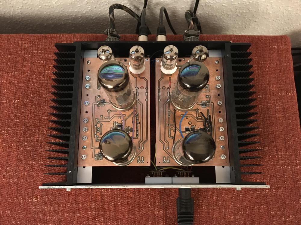 Something like this?? Board size 3.95in x 6.9in, same as I use. Probably a lot easier if bigger boards.
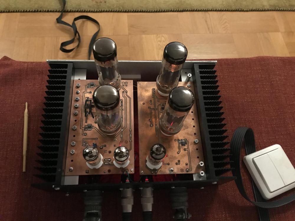
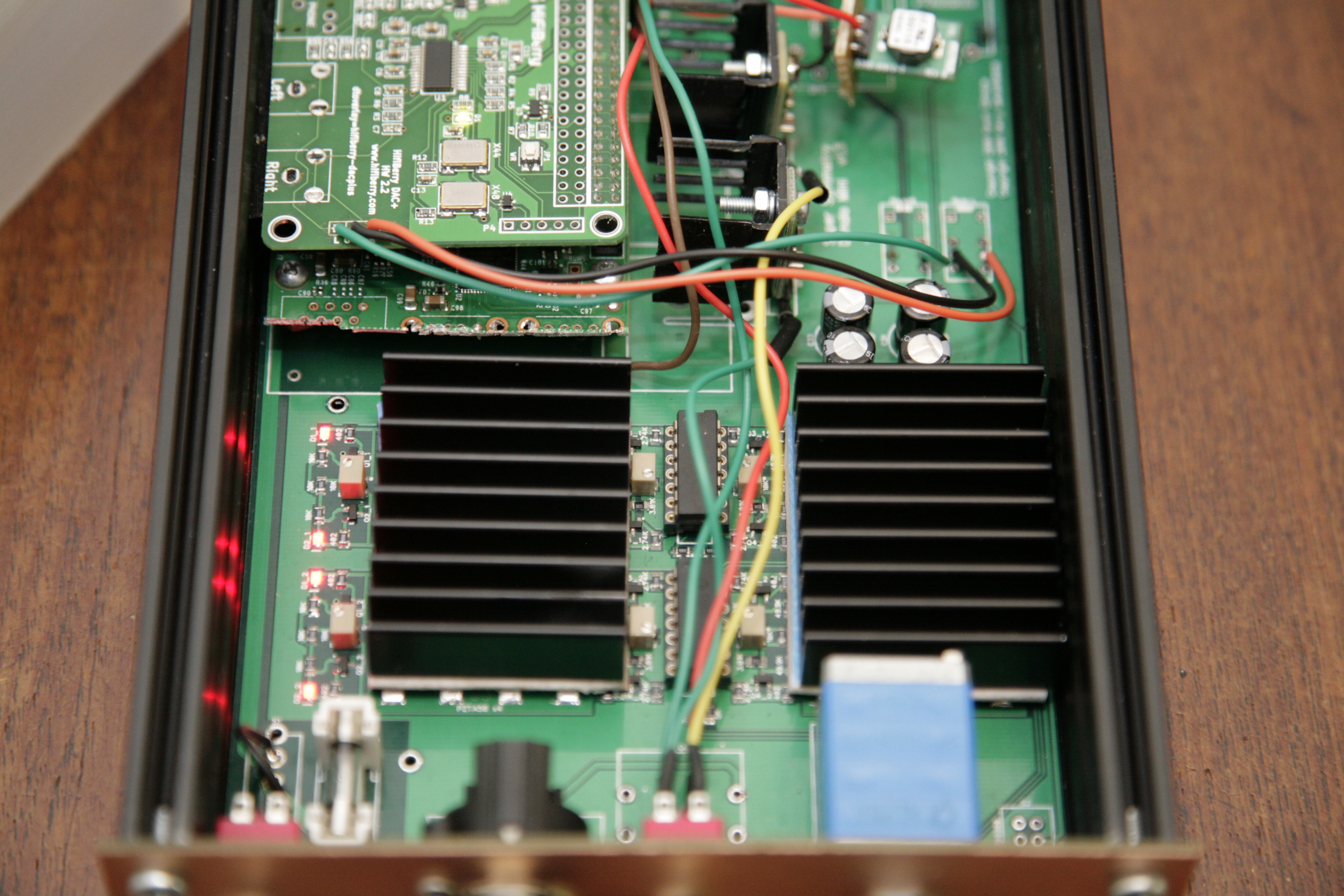
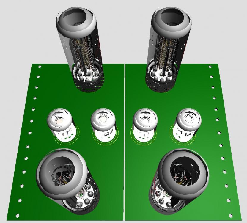 From an article in New York Times - Piano Lessons in the Panopticon by Elias Muhanna.Replaced the original right board with the dual small tube one. First power on without any funny smell, smoke or explosions. But both outputs at positive rail voltage. Back to schematic and after a while I found two mistakes I’ve done. I managed to correct them on the PCB which now looks awful but it plays music all right.
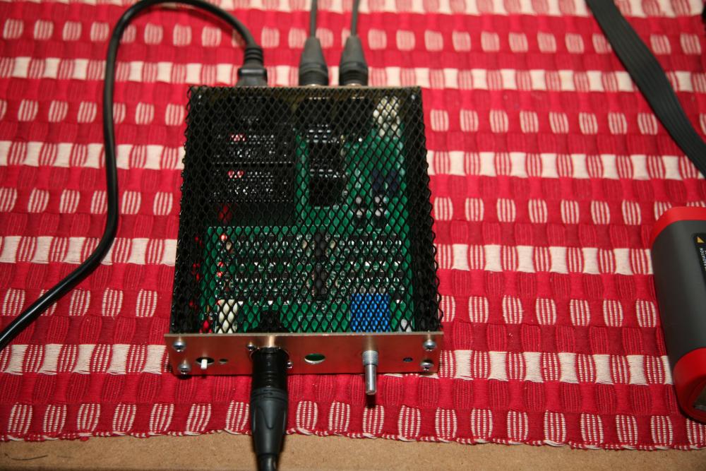
 Board ready to be squeezed in in the box.
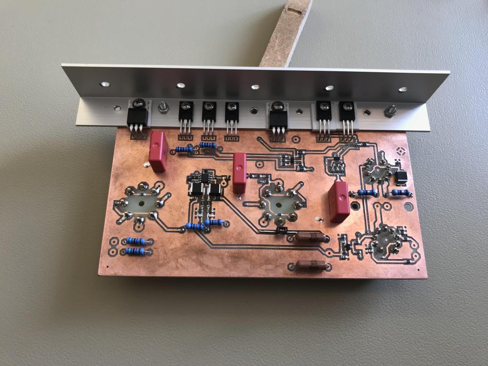 Milled and drilled right side board today. Same size as the single tube input version. Here single and twin small tube side by side. If lucky Mouser package arrives tomorrow and if Proteus ratsnest works it should play soon. If I haven’t done something stupid…
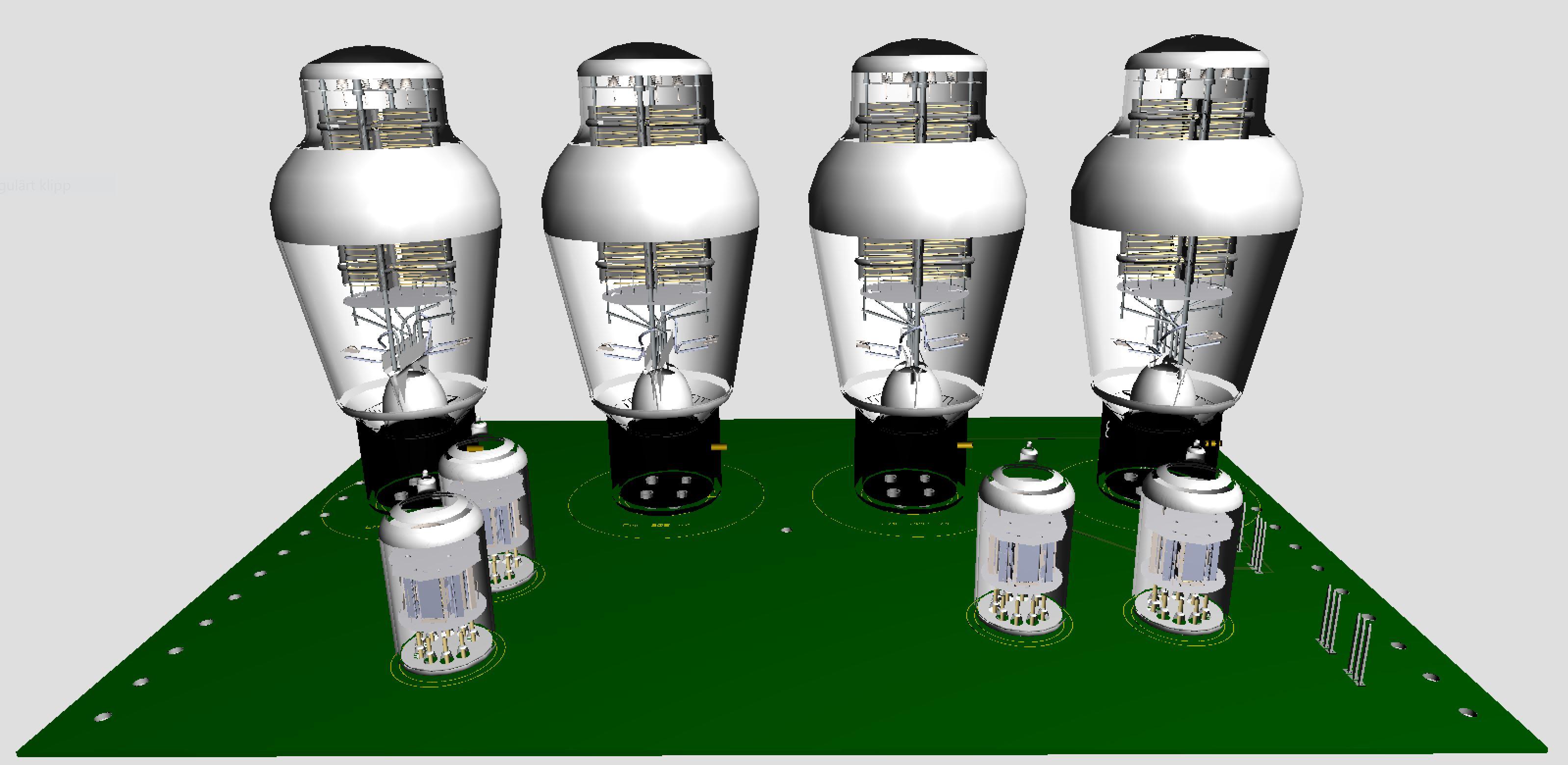
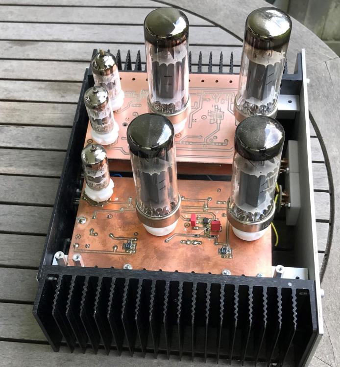 There is not much new under the sun.I think I’ve done some real progress with twin input tube grounded grid. The board will be made with a CNC router. The red lines show the route for the end mill, 15mil or 0.38mm with 0.5 overlap so each cut is down to 7.5mil.
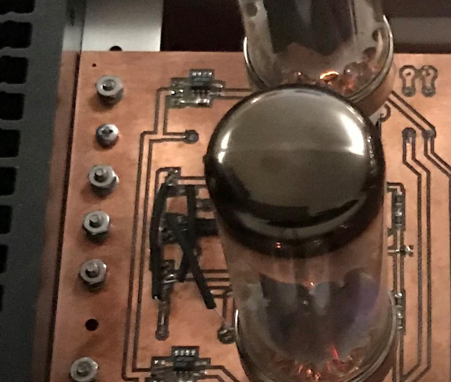
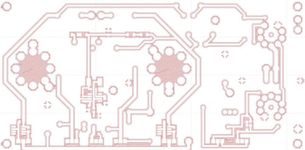 I use ceramic insulator, insulating washer 7721-3PPSG and steel screws. The washer shaft is long enough to stick down in ceramic insulator a mm or so. I think this combination is used by more people than myself. Can you test this combination (or you already did?)? Preferable with some messy non-conductive thermal paste.@Kung Interesting. Can you provide more information, pictures etc. of what you’ve done? I love all kind of modifications.I usually work with imperial system in Proteus as I find it pretty convenient. For my 10K Afternoon Run the metric system is way more comfortable. The voltage cross 2sa1486 is 580 – 590 V. That’s why I chose between stn9360 and 2sa1486. I guess you could use a pair of ksa1156 and split the voltage cross them.


Important Information
By using this site, you agree to our Terms of Use.