JoaMat
High Rollers
-
Joined
-
Last visited
Everything posted by JoaMat
-
How to make the servo less complex?
-
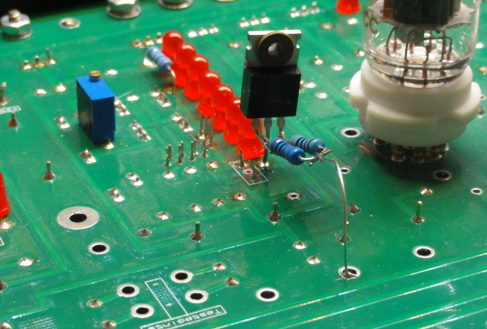
The Drum Major leads the seven LEDs.
-
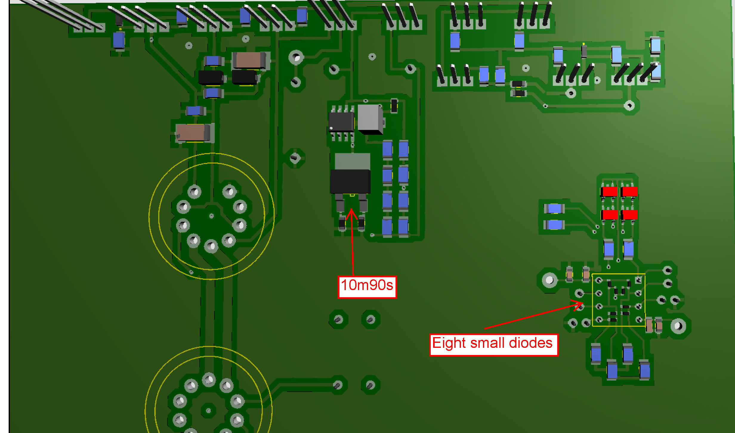
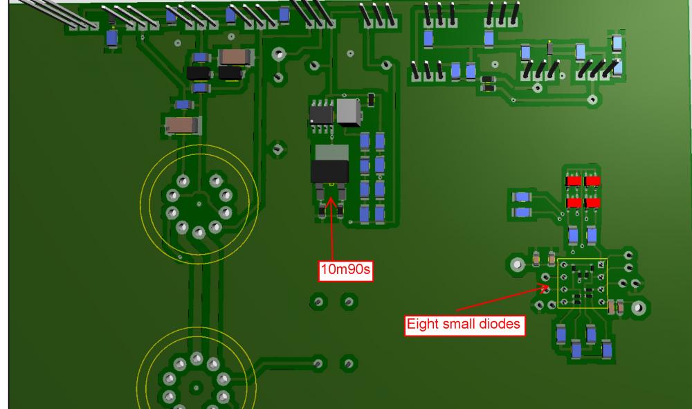
Managed to squeeze in the eight diodes under the lf353 op-amp. Batteries resistors killing some 730 volt in series with the LEDs, or in my case lt1021, replaced with 10m90s. Works great in layout software. In real life -
-
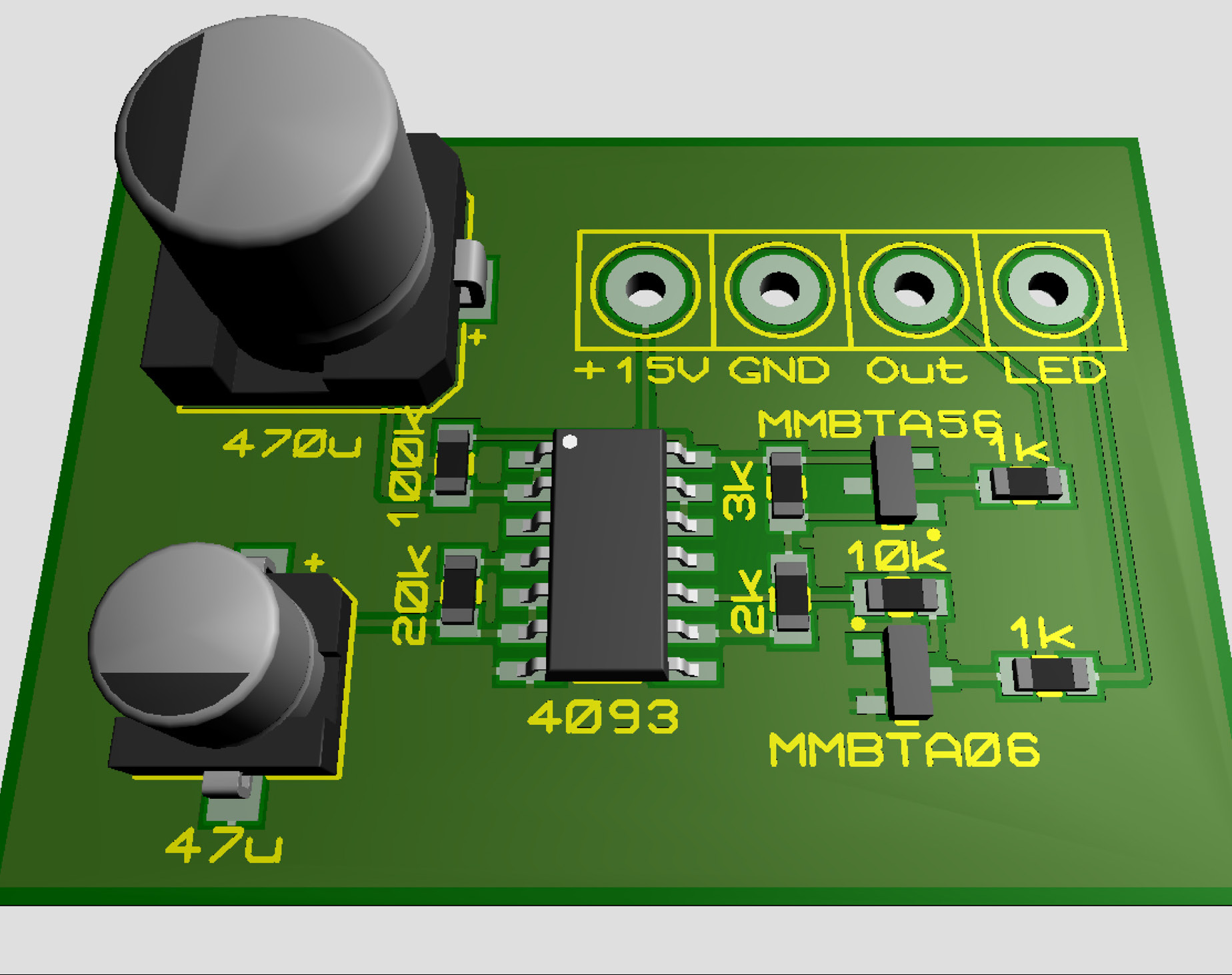
Here is Delay circuit.PDF schematic. R1/C1 determines the delay time and R2/C2 flashing frequency. 12 V is fine, I use this circuit in two T2 power supplies with 12 volts. For time calculations google "R/C time calculation". Values in schematic gives me approximately a 50 seconds delay.
-
-
If dual tube input. One tube as upper device and the other as lower like T2 or one tube each side?
-
How about a “dual section” tube input similar to the T2?
-
How about increasing the 6DJ8 plate voltage? Might need additional ksa1156, what else?
-
I consider this is a fact.
-
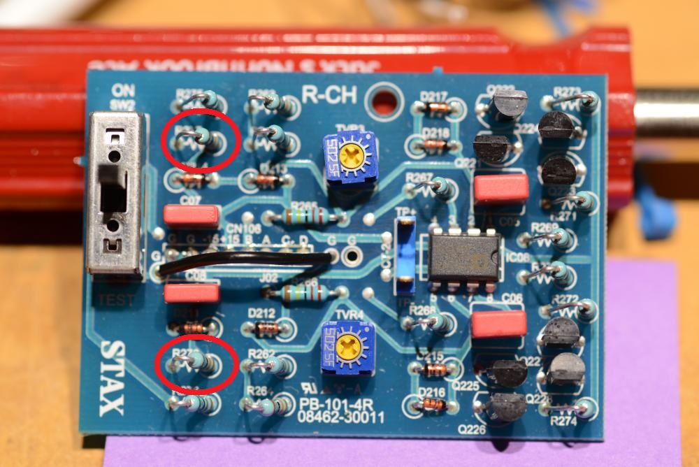
Kevin, function of switch in test position? Resistors in red circles below, have something to do with test?
-
-
Thanks for schematic. Guess I'll stick to the t8000DR. The servo is interesting though.
-
Thanks for clarifications George and Michael. The servo (opto servo) I'm talking about needs both OP27 and 4N25 installed and the jumper next to the 4N25 shortened (do not shorten the other jumper). The trimmer must be set high enough. The opto servo is only capable of lowering the offset set by the trimmer.
-
I use a similar opto servo as on Kevin's boards. Differences are KSC2690A for PZTA06, VOL618A for 4N25 and no resistor/trimmer cross KSC2690A. This servo works instantly on my DIY T2, Carbon, Grounded Grid and Grounded Grid with tube input. The amplifiers also have balance servos. With multimeter one decimal resolution I read 000.0 at the outputs. My impression is that the opto servo works well. I've no idea what the problem with your Grounded Grid is. The servo works on your Carbon then it should work on the Grounded Grid as well. I'm sure you will solve this, might take some time though but it will be worth it.
-
Happy Birthday!
-
After a second thought. Probably a bad idea put a test pin at pin2 OP27, might affect the servo. But the small variation at one output could very well be variation in the balance. +0.160V then you have -0.160V at the other output. I have four amplifiers with similar servos and they all have perfect offset behavior and the servos kick in instantly.
-
Turn trimmer up to max resistance. Measure voltage at pin2 op27 to ground with one decimal resolution and I bet you'll read 000.0 within a few seconds after applying the high voltages. That servo works.
-
Thank you pose, pixels appreciated. Give me the opportunity to steal good ideas. I like the led stax connector. Can that be bought somewhere? At the PSU, there seems to be something Arduino on the back panel - what's that?
-
You wanna circlotron? This is a circlotron... ... just where I live.

-
Nice. Big knob is volume control? But the small one is? Is there some light in the Stax outlet or is it just look like it is? Nice indeed. More pixles, please.
-
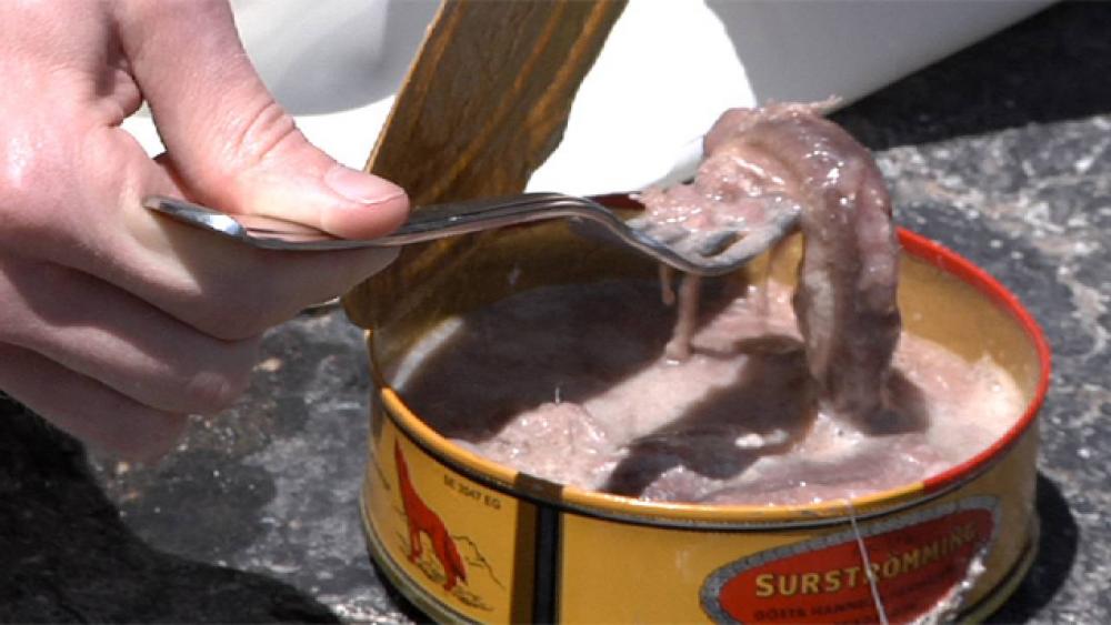
I love fish, salmon and lutefisk are fantastic. But surstromming, that’s awful. Eat surstromming for three months then you are light light weight.
-
好,謝謝。我是大如相撲選手。
-
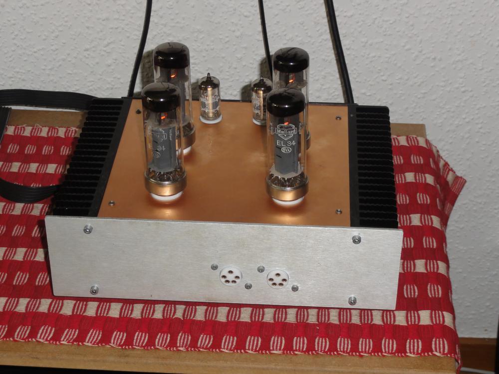
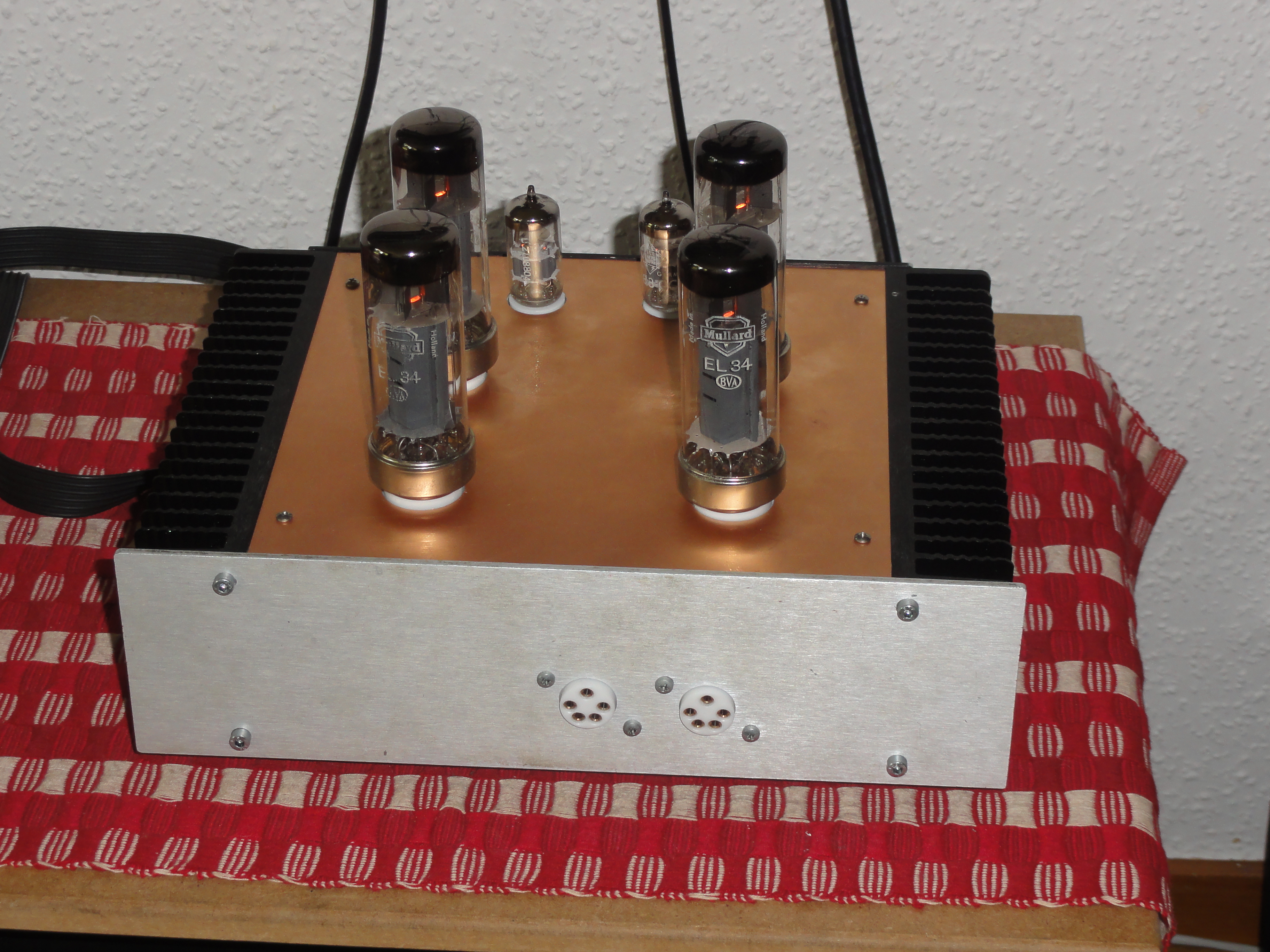
Still another rainy day. Here with DHT. Shortest distance between tubes is 0.3 inch. This built was not intended for the huge triodes… ...but it is a good sounding thing.
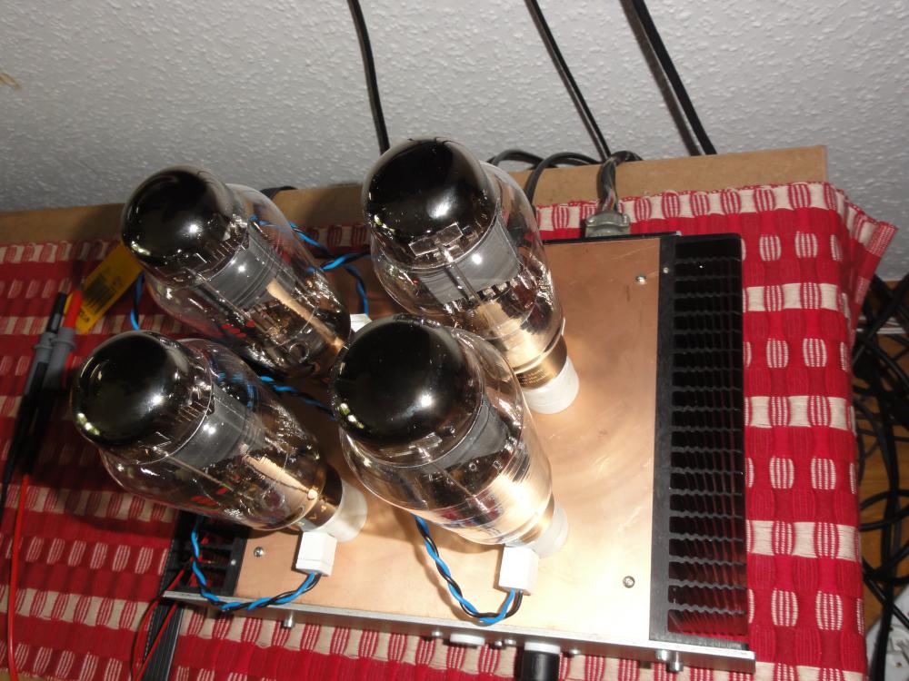
-
-
Look! Top plate, 1.6 mm copper clad single sided. I do think we have copper polish somewhere in the house…