GeorgeP
Returning Member
-
Joined
-
Last visited
Everything posted by GeorgeP
-
I have a couple jugs of acetone so will try that out - I mainly use it for cleaning my bike rims, never thought to try it for this.
-
Had heard of oil before (and WD-40 in particular) for packing tape glue, but was worried about thoroughly cleaning the through-holes after. So no problems on that front?
-
Anyone have any quick tips for cleaning all the packing tape glue off the boards? With some work alcohol worked on small patches but some boards are covered, so looking for alternatives...
-
It was certainly fixed by version 0.5.
-
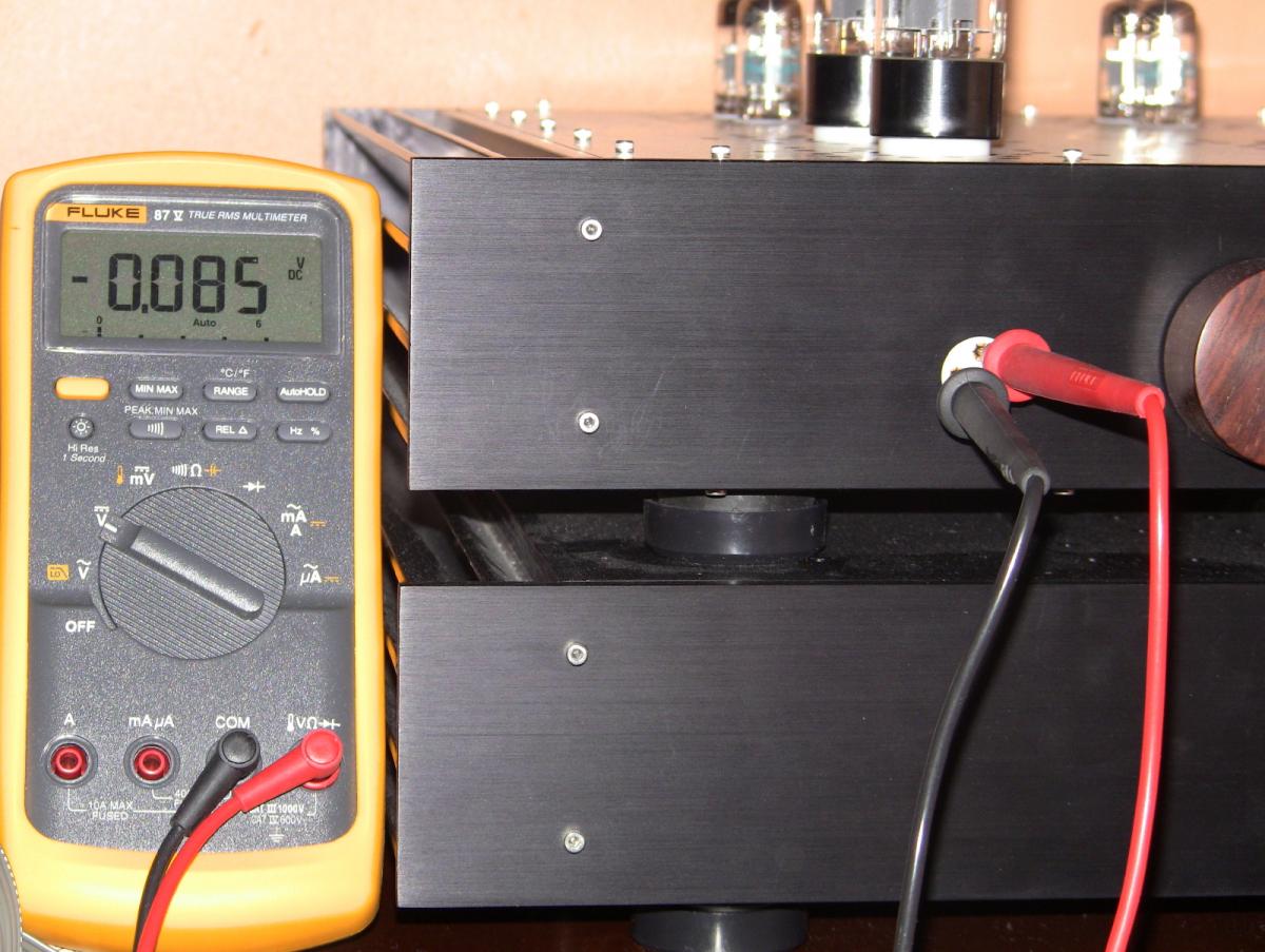
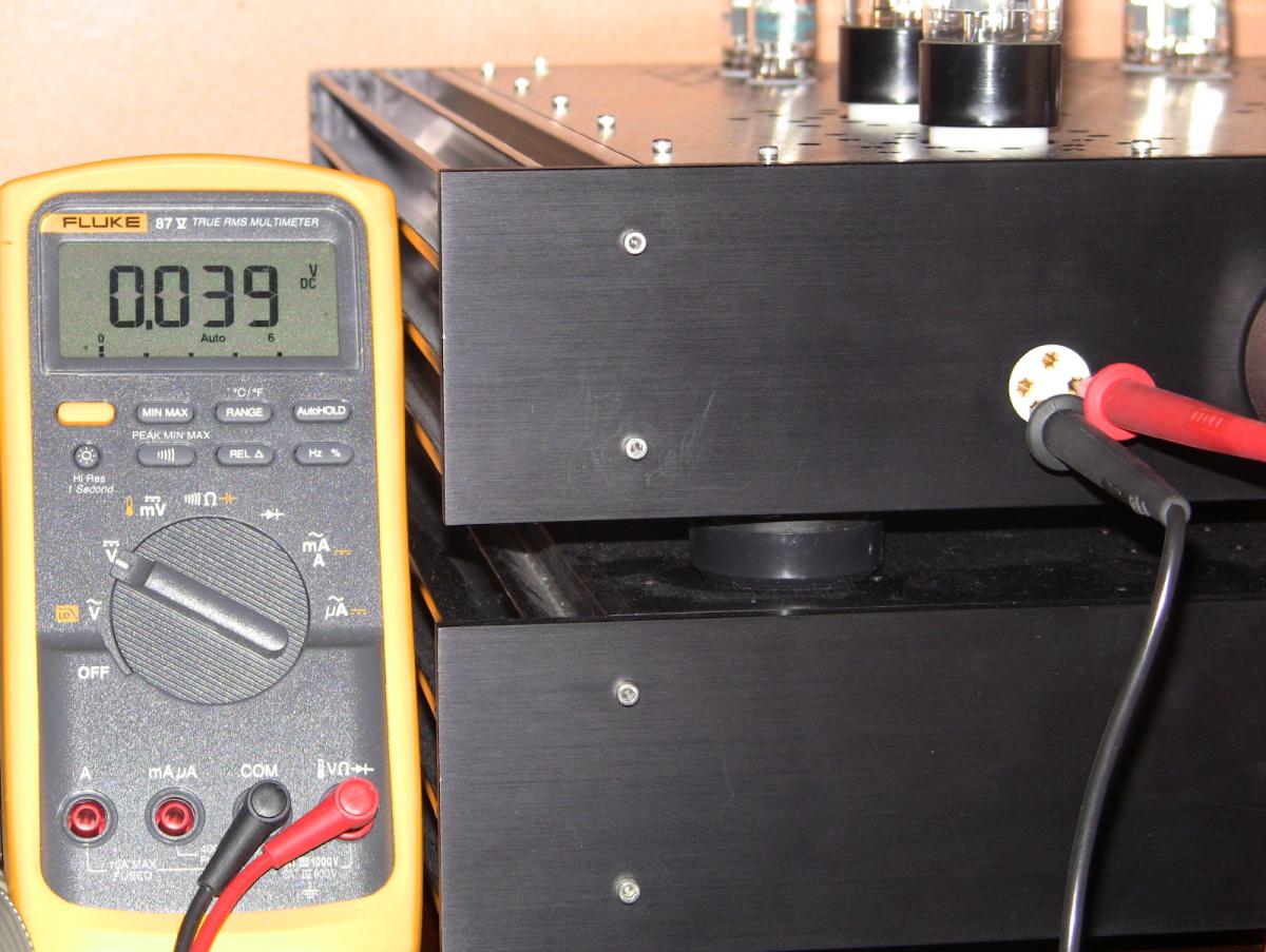
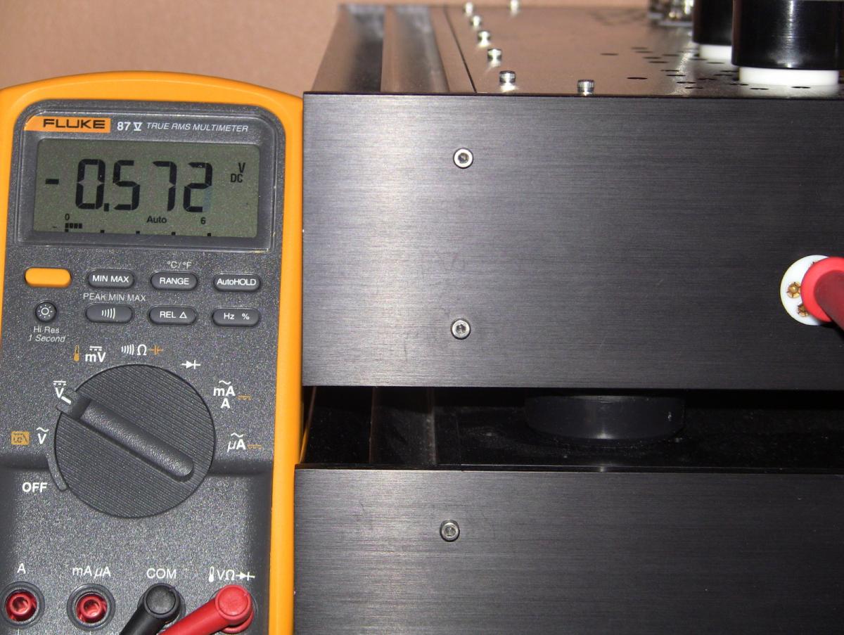
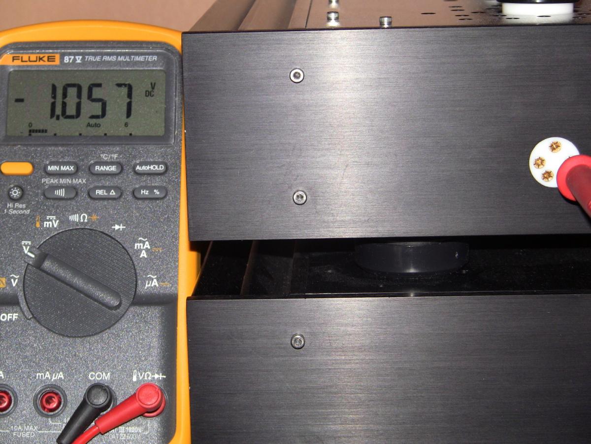
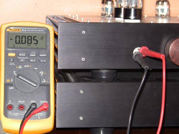
What are the balance and offset after a cold start? Would be interesting to know.
-
So the effect would be the same in how you have done it. The two ground wires are connected in one spot in the amp box then split between the two umbilicals and then reconnected in the psu box at the IEC (my XLRs are also connected as yours are). Not sure if that in and of itself creates a ground loop, but maybe where it is grounded as well in the psu chassis which in turn connects to the amp ground - not sure. But I can say it is dead silent at all volume levels and with volume turned down all the way (max resistance). If it is a ground loop, it makes my head hurt trying to conceptualize it - sort of like the "Inception" of ground loops - a ground loop within a ground loop. Maybe Kevin will weigh in on his design considerations.
-
I meant to ask, how did you end up wiring yours, and how did the LEDs respond when you first turned it on? Thinking back I am pretty sure I wasn't imagining things, but it was about 4am and anxiety was running high so who knows - I certainly would not go about trying to recreate the effect.
-
Here is Kevin's post I was referring to - took me a bit to find it.
-
Going by memory: Circuit ground (pin P) from amp to psu board. Then as directed by Kevin (and difficult to see in one of his photos, but you can see it in mine), a short wire from the psu board ground to the nearest screw. Continuity-wise, this is connected to earth ground on IEC via the chassis. Chassis ground (pin K) from amp to earth ground on IEC. I know a few others had slightly different chassis grounding schemes. Hope I didn't miss something.
-
Do you have any pictures of how you have it wired?
-
Thought I would would check for fun to see how things were doing. The servo on this thing is simply amazing - just rock solid with barely any up and down movement.


-
Congrats on making a most difficult decision.
-
Good price, but if people are intending to use them for the T2 i think they need to be 15mm.
-
-
My first MKI was 71xxx and I preferred the 009. I currently have the SZ1 (BL) and cannot detect any differences with my earlier 71xxx. Going by memory though (we know how reliable that can be when it comes to listening impressions) as I did not have the SZ1 and the 71xxx at the same time.
-
Same price as the brown - I see they have actually now added the colour choice to their website. I bought one as a back up not long ago but the colour option was not on the website at the time - probably added it due to inquiries.
-
Which 007? Never heard the Omegas, but have the O2 MK I and the 009. Prefer the 009 by a narrow margin - Head: 009, Heart 007.
-
I had understood that there would be less expansion/contraction with the PEEK screws over the metal ones - but maybe that isn't the case. Also, not sure if anyone has compared the real life heat transfer between using PEEK with less torque versus using metal. I can't say this is indicative of sufficient or proper heat transfer, but the heatsinks on my T2 get stink'n hot, even the PSU. In any case, I am sure the life span will be affected regardless of whether it is PEEK or stainless, the question is to what degree, if any, are there any measurable differences. I used a mixture of stainless and PEEK, using stainless where I could use the larger Aavid shoulder washers and PEEK where I could not (I recall Craig or Kerry actually drilled/reamed the transistors so the shoulder washers would fit and used steel bolts throughout).
-
Yes.
-
The T2 has the amp section in one box and the PSU/transformers in the other, and if I recall correctly the amp section had 2 separate grounds (circuit and chassis) that went via the umbilical cord to the PSU box where everything was then essentially tied to the earth ground. Not sure that answers your question though, but I recall Kevin and others placing some emphasis on ensuring the grounding scheme was adhered to properly.
-
Really great, Kerry! Can't wait to see it all cased up!
-
You can still get the black MK1 headpad without 007 MK2 markings from Stax USA for the BL model but you have to ask for it. And yes, the cable would still be brown.
-
I remember this had been how most people utilized the 1968s, but is it a given that that you cannot use a 500v PS with a 1968 build given the sanyo parts are good to 900v? I had thought Kevin or Birgir had posted on this previously but I am having trouble finding it now.
-
Would the original board size still fit the case or is it no longer compatible? Also, wouldn't it be easiest to just use the dimensions of KG's custom case with off the shelf heatsinks and connecting brackets (because I would expect extruded panels to cost more), than to do something from scratch?
-
I am not much of a gamer but my brother sent me this link for 8 popular (although a little dated) games. You essentially pay what you want and the money goes to charity, except that you have to pay at least above the average (which was $4.73 when I signed up). Could be useful for some folks and the money is going to a good cause. https://www.humblebundle.com/?utm_source=MadMimi&utm_medium=email&utm_content=Introducing+the+Humble+Origin+Bundle!&utm_campaign=20130813_m116906107_Introducing+the+Humble+Origin+Bundle!&utm_term=Humble+Origin+Bundle