


insanity
Returning Member
-
Joined
-
Last visited
Everything posted by insanity
-
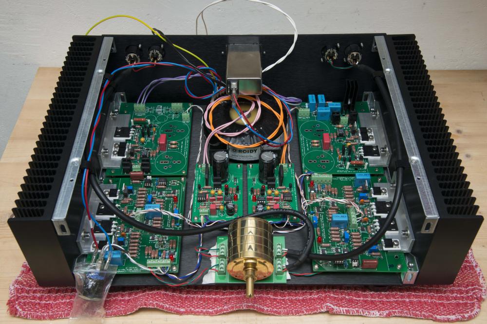
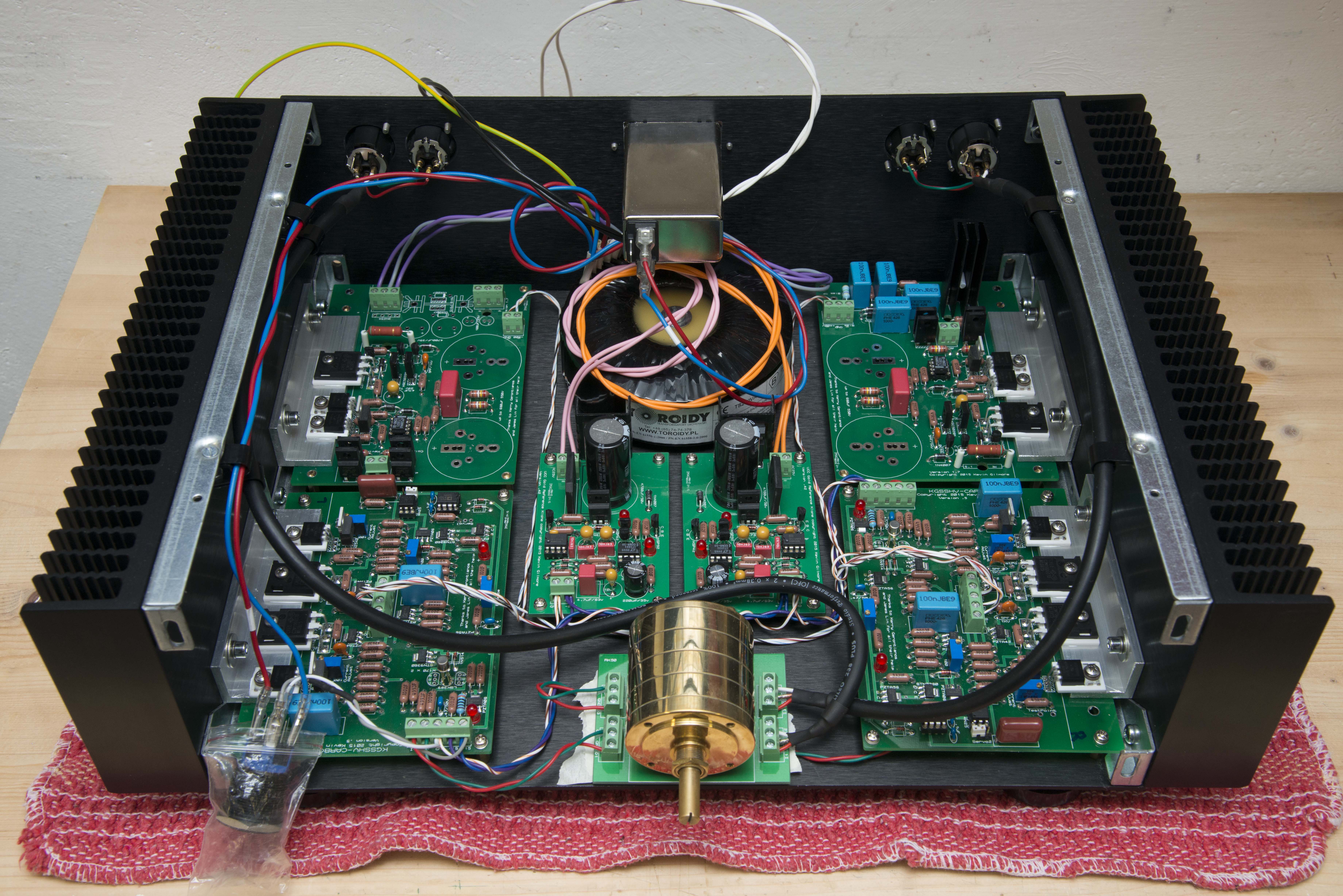
This is my progress so far. Waiting for the caps. Rest is more or less done. To answer some questions before they are asked: My transformer has 15-0-15 and 2x 18vac windings, because I was undecided which lv psu to use, when i ordered it. As you can see, I have decided which one to use, and connected the 15-0-15 just to prevent the wires from dangling around. I will clean up the transformer wires when I finish it. Any other questions are welcome ;-)
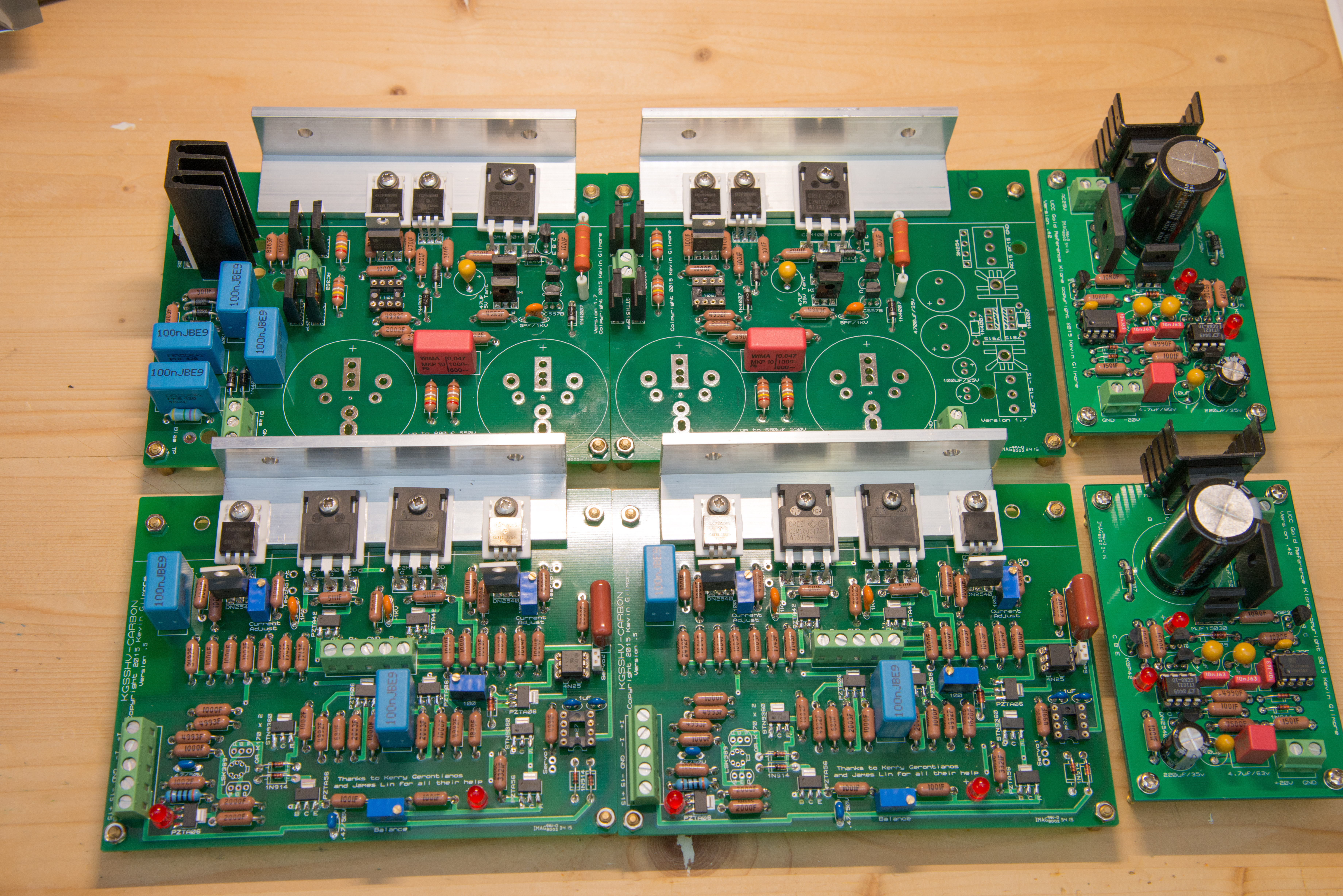
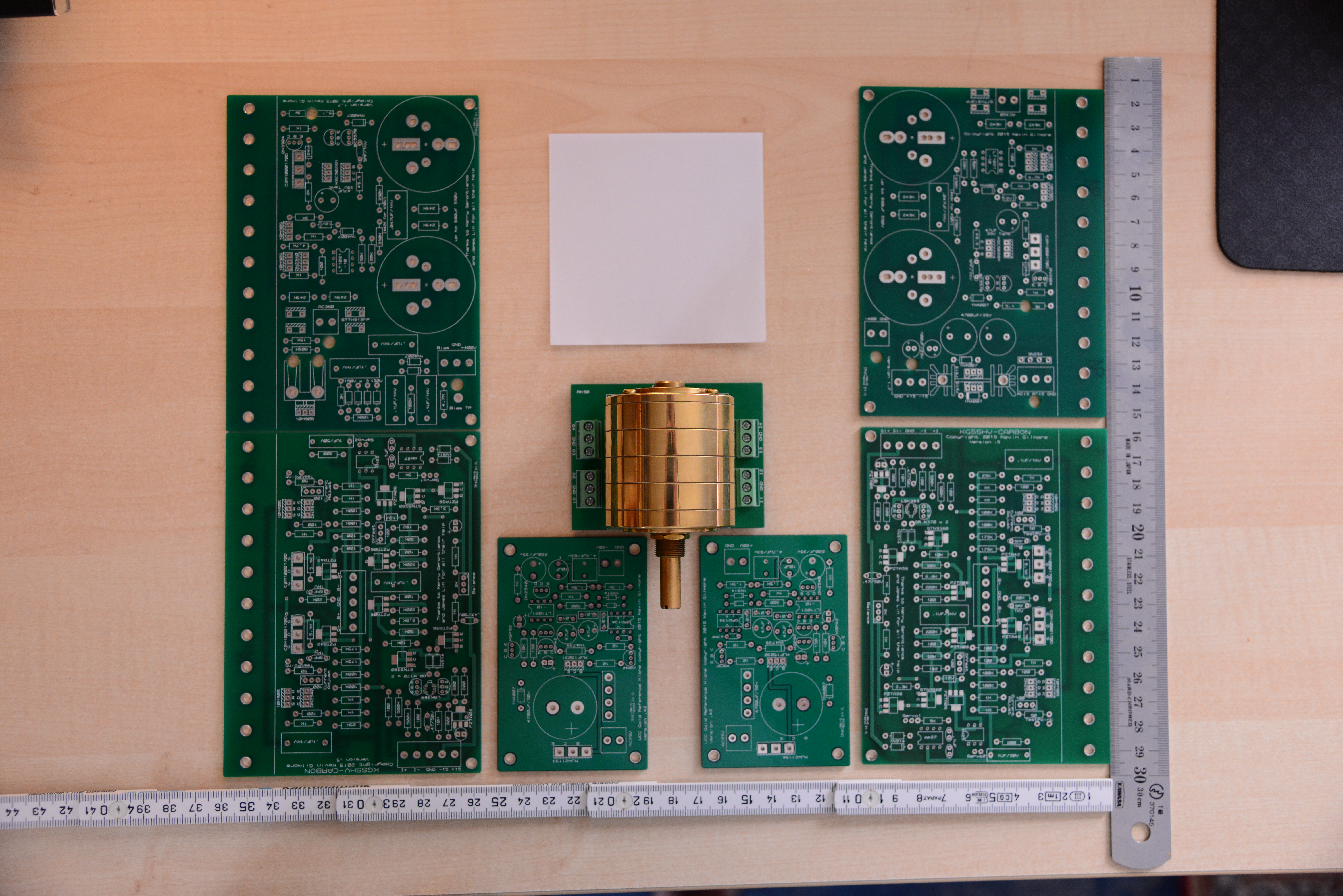
 Actually, I am And this looks soooo cool. I really love it. Are the bent copper tubes for ventilation? And what about fingerprints on that copper? Only touch with white gloves?Wonderful. I'm ready ;-)The resistors / resistor value labeled "I" are for the version that uses the IXYS parts as output devices (upper right heatsinks of the board). Since you have the 4686 you don't need to populate the 1k and leave it open. Furthermore you need to use 180R and not 250R. On other versions of the board instead of "I" = IXYS, the designation "M" = mosfet was used. Since you are using the IXYS as the current source (lower left heatsinks of the board), you need to populate the resistors labeled "I" in this section, and leave the ones labeled "A" = sanyo parts open. This also applies for the LED in this section.Ok I need to correct myself. The 4686 is fine for 500V. It's indeed just the 1986 (which you don't have anyway) that is not suited for 500V.It looks like this thing was built with the 4686 as output devices which as far as I know are suitable for the 500V version. If you want to go for 500V, you would need to replace them with ixys parts. Which I would not recommend, since the 4686 is definitely superior sound wise (I changed my kgsshv from ixys to 4686 some time ago, but I ran it at 450V anyways). I would rather get a transformer suitable for the 450V version and rebuild the PSU board for 450V as well.Did you elevate the big power resistors on the PSU board a bit? I cannot tell from the pictures. They should be a bit above to board, for better heat dissipation. On the Amp board two disc caps are missing in the input section. The PSU board also misses a few part (one film cap and two diodes) Furthermore it looks like you are using non-isolated diodes in the bridge rectifier part (although I am not totally sure form the pictures). If so, it will arc and blow up...I used the following caps on the LV board: http://www.mouser.ch/ProductDetail/Nichicon/UVZ1H472MRD/?qs=%2fha2pyFaduhJNBfNrn1z57sARJAwCa5EYPGgZi6O34PyKHzMMWJAtA%3d%3d http://www.mouser.ch/ProductDetail/Nichicon/UHE1V221MPD6/?qs=sGAEpiMZZMtZ1n0r9vR22VnKtxyD4xsRvYMdZpGna94%3d Which are both rated to 105C, in case you were refering to my boards. I'm using rn60 1% resistors in almost every place. I am surprised how accurate the GR LV is. They read +15.005V and -15.006V. As you might have noticed I also had to cut a strip off the ceramic insulator pads on the GRHV PSU because the two adjacent 10m90s wouldn't fit as is.i just wanted to share 2 things i noticed during assembly of the GB amp boards. The Dn2540 and the 100ohms trimmer adjacent to it, are quite a tight fit. I used vishay trimmers and the dn2540 has to be soldered with a slight angle. Maybe the bourns trimmer have slightly different dimensions? Furthermore, I noticed that the holes of the 1uf 50v cap of the servo are quite tight. This probably doesnt affect caps with this rating. but i had 1uf 250v and the leads are a bit too thick for a nice fit. I also must mention that the boards are very good quality. I have never soldered on boards the seem to suck in the solder that good.IMHO the KGST doesn't need such a device... Just turn everything on with one switch.Thx Pars. Will add these in the right size to my BOM. For the case layout I guess I will just try one version, if it works, fine - if not, try another. I also thought about mounting the amp boards vertically, but like that, adjusting the trimpots will be a pain, with everything put together and I would like to avoid that. Anyway I am very interested how others want to build their carbons.@ johnwmclean I think thats a interesting idea. I will need to check if the lv boards fit nicely somewhere above the other boards, when I have all the boards populated. Especially because of the capacitor height. @spritzer Therefore having the transformer as far away from inputs and outputs is necessary? I thought the input wiring was much more prone to picking up noise? I therefore conclude that maybe the better option is the do the layout as pictured above, but with the xlrs on the side of the chassis instead of the center (above the psu boards, there should be enough space). The IEC can be in the middle. I could run the input wiring along the side of the chassis (under the cover, maybe in shielded cables?) and move the RK50 to the front. Like this the input wiring are as far away from the toroid as possible (btw, I will get a custom toroid with shielding). The output wiring would be short and wouldn't need to pass over the toroid. Does anyone know, if mouser has something like this?Since sorenb reported that there might be a difference in sound when using amb's psu for the LV Section, I thought I would just try the GR LV instead of the 7815. I won't be able to tell the difference, because I am not planing to populate the 7815 unless the GRLV blows up or something.I am planning how to arrange the various boards in a 3U dissipante chassis from modushop (see picture below, white paper = toroid). Are there any suggestions on better arrangements of the boards? IEC and XLRs would enter the chassis over the toroid. I was thinking of various other configuraitons such as moving the toroid and the HV PSU boards to the front, the LV boards to the middle and the RK50 all the way back. Like this the pot and the amp sections would be on the rear of the chassis. Any ideas of what the best configuration is? BTW: I am planing to use the chassis bottom as a heatsink for the GR LV supply. I think this should be sufficient, right? Also thx to xianghao for providing me a RK50 pcb.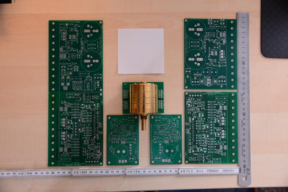


Important Information
By using this site, you agree to our Terms of Use.