mwl168
High Rollers
-
Joined
-
Last visited
Everything posted by mwl168
-
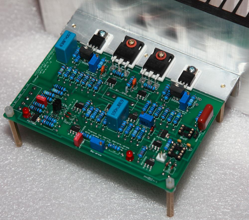
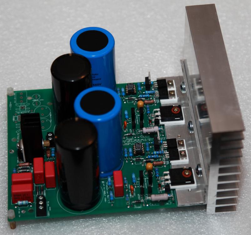
Thanks guys! @insanity: the insulation pad is the Aavid 4170G. These are wider and longer than the 4171G but slightly thinner (1.57mm vs 1.77mm). I just happen to have them on hand. These won't work for the 10m90s on the GR HV PS board because they are too wide. For the GR HV PS I use 4171G. The heatsinks are sourced from heatsinkusa. They are the 8.460 width one cut to 4 inch long. I don't know what's their spec (did not find the information on the website). I bought them for testing purposes like what I am doing here. On the hind sight, I wish I had opted for larger ones. @Sorenb and John: yes, the heatsinks are too small for the HV Carbon @ 20mA - after 20 minutes or so of powering on, they got very warm to the touch. I was a bit surprised. I have picked out a few possible chassis for the HV Carbon already but will need to re-evaluate after this empirical experience.
-
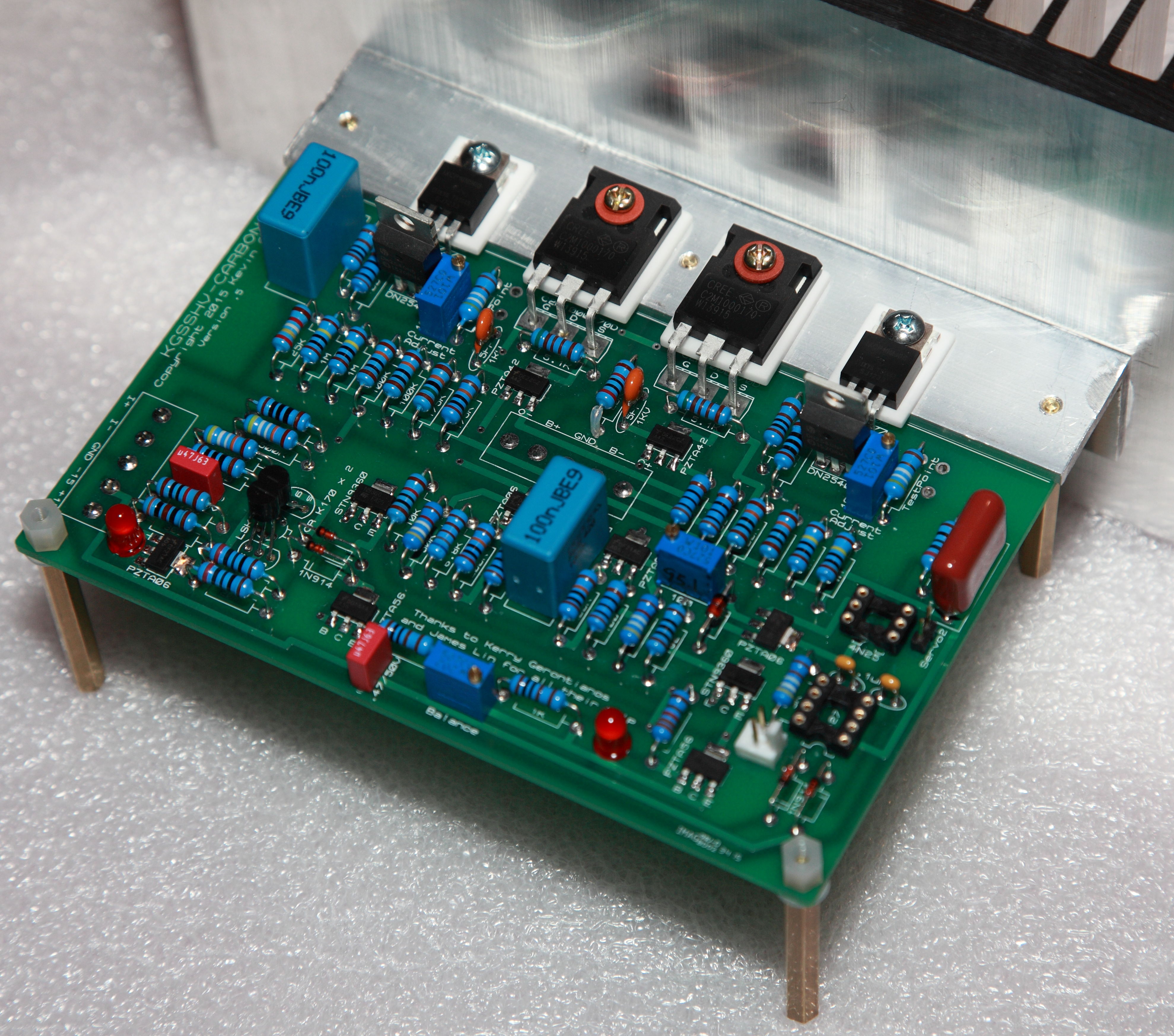
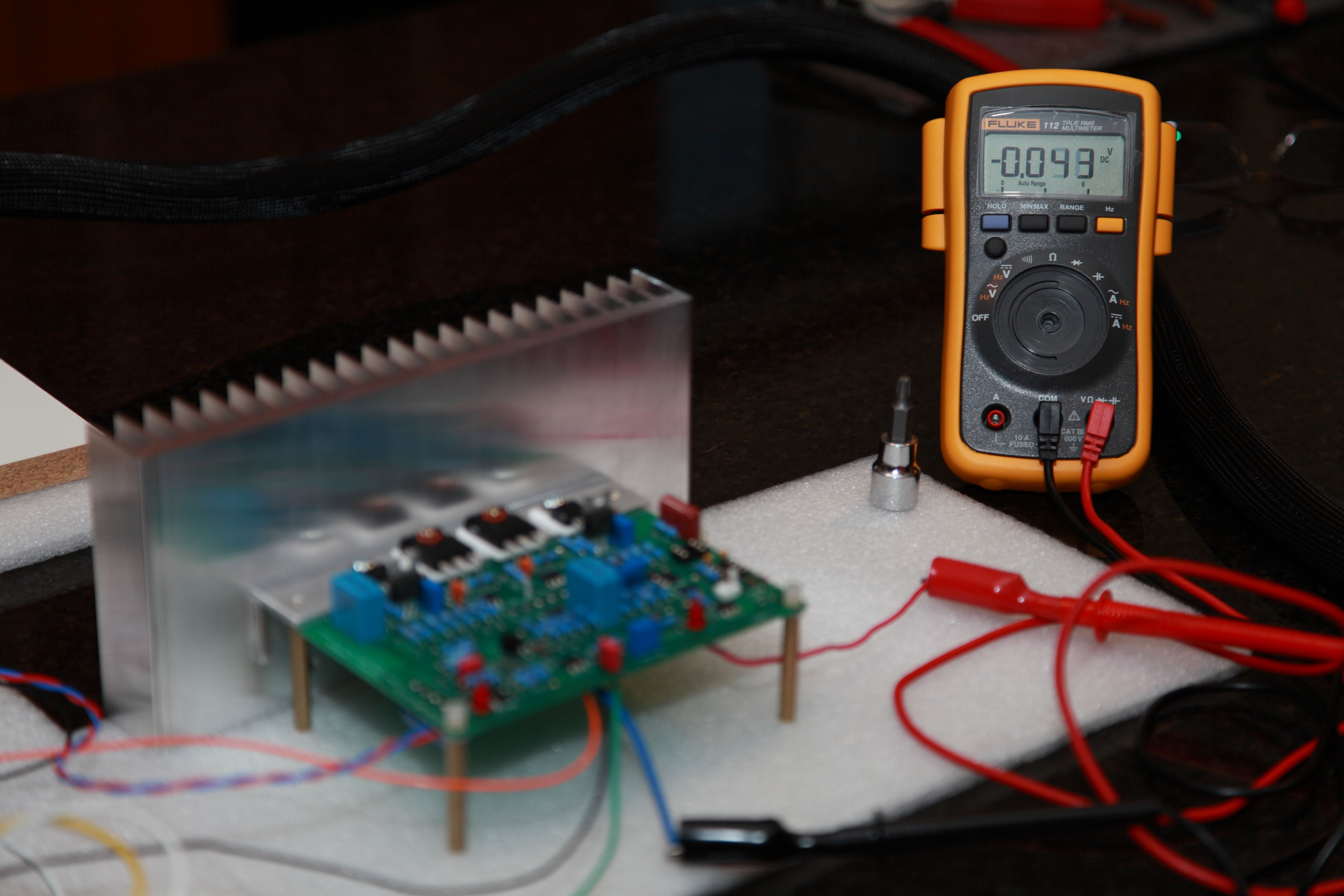
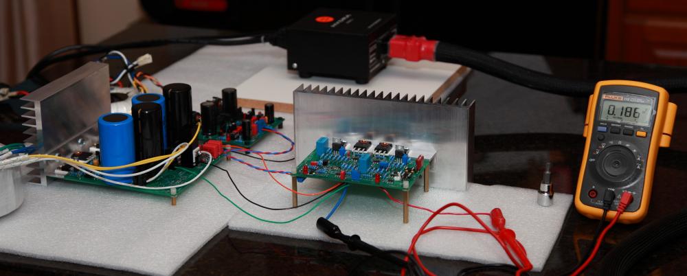
More progress today testing my HV Carbon build (V5 board from the GB). I am running 20mA (1.00VDC measured at test point) and have substituted the 182R tail resistor of the offset VR with a 100R one. No problem zero-out the offset and balance. A few observations at start up (I have all VRs adjusted to mid point of its value before soldering on the board, I also hand measured and picked all passive parts including the LEDs except a few tiny capacitors): 1. the test points measured between 0.71V to 0.76V 2. the balance is around 3.8V 3. the offset is around 38V I also found the following sequence of procedures worked well for me for adjustment: 1. Adjust the two 100R VR next to the test point to read 1VDC - my desired 20mA output current 2. Adjust the 2K balance VR to as close to 0V as possible (it'll drift a bit) 3. adjust 100R offset VR to as close as 0v as possible (it'll drift a bit and also interact with balance adjustment) Next will be to wire up the input and output connectors and see if I'll get music. By the way, this thing runs HOT, much hotter than my KGSSHV. My test heatsink got very warm to the touch. Here are some photos:

-
I kept losing my sign-in tonight when I switch between forums. Has anyone experienced the same glitch? I did not have this problem ealier today. I am using Safari browser on an iPad.
-
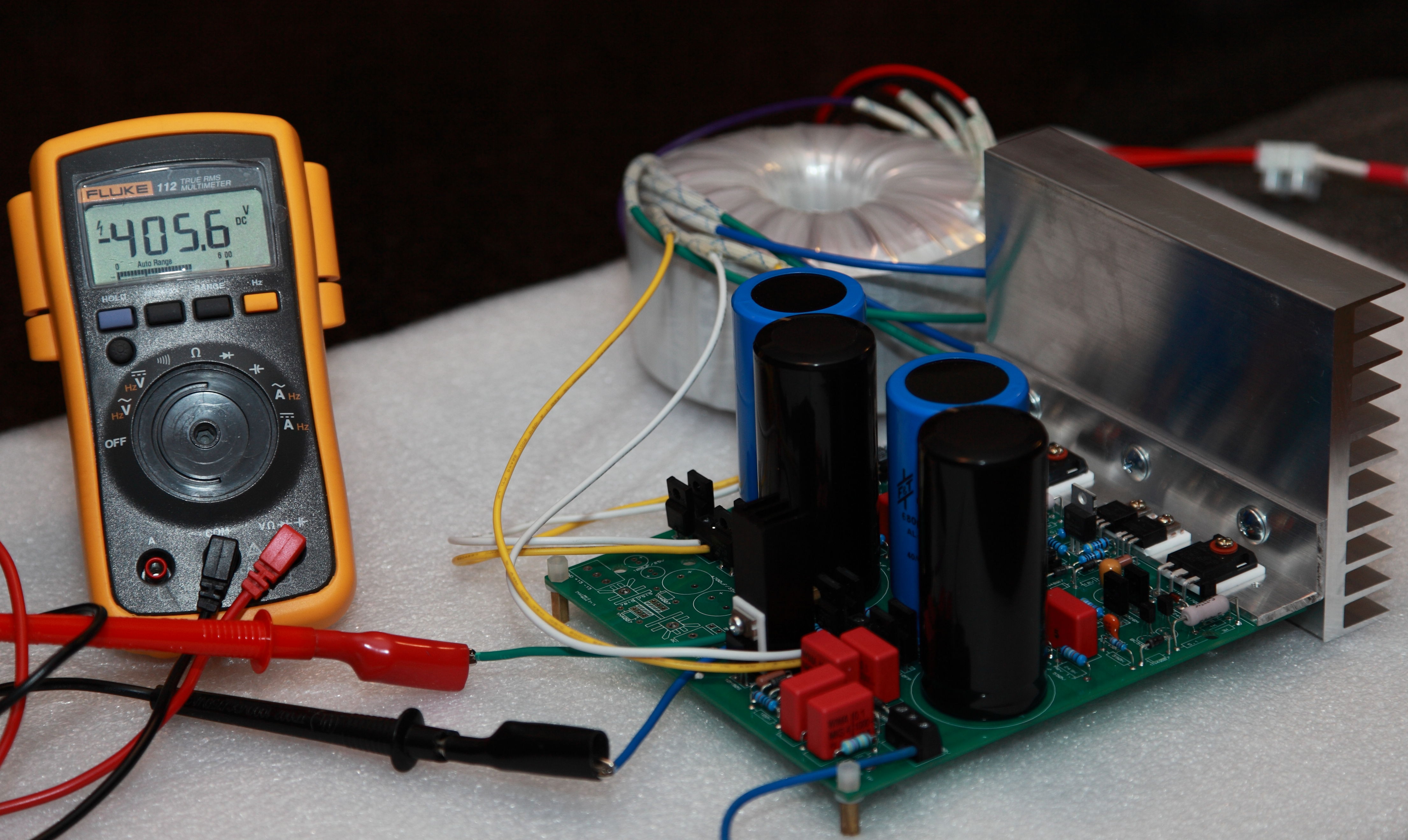
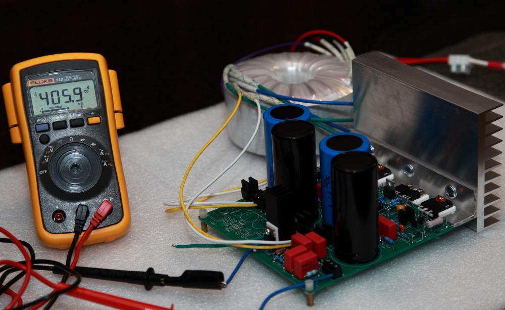
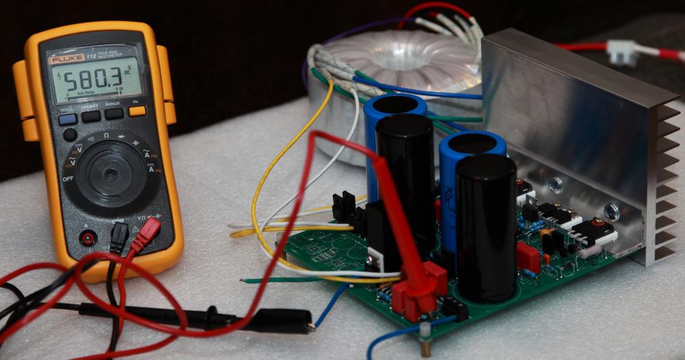
Right at the heel of kingofsnake, I got my GoldenReference HV Dual up and running an hour or so ago. I don't remember if anyone else has reported successful build of the GR HV Dual board from the GB. I have not hooked up the PSU with load but the initial testing looks good. This particular board is configured for +/- 400VDC output. I hand-measured and picked the resistors and I ended up getting +405.9VDC/-405.6VDC. Close enough. It's been a long time coming and many thanks to sorenb and Jay for the caps GB to make this possible. A word of safety caution; I am using 680uf pre and post regulation filter caps. Without load, 60 seconds after shutting down AC supply to the PSU, the positive rail still measured 262VDC. It took 163 seconds for it to go below 100VDC and 357 seconds to go below 1VDC. At that point, the bias still measured over 300VDC.

-
What should I rinse with? I've been using a semi-sharp pin to scrap off the hardened flux followed by scrubbing with a tooth brush and high purity isopropyl alcohol (90% IIRC). This cleans the flux well but tends to leave a film of residue that is viible under certain lighting conditions.
-
Count me in for 20.
-
I wired up a 25VA toroid with 18v secondaries to the GoldenReference (set up for +/- 18VDC) tonight and as can be expected the heatsink temperature dropped significantly powering the same Susy Dynalo amp. They still run warm but no longer hot to the touch. I guess the take away lesson for me is to allow sufficient headroom choosing the transformer but not to get too overboard. Spent a couple of hours dialing in the offset of the Susy Dynalo, finally sitting down to listen to some music. Happy to report everything appears to be in good working order. I settled on 18VDC rails and 312 ohm for R38/R39 which, after warm-up, results in about 19mA per output device (380mV voltage drop on the 20 ohm emitter resistors). The MPSWx6 output devices run very warm but not hot to the touch.
-
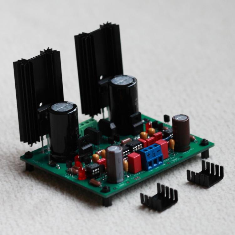
Here is a pic of my GoldenReference LV PS. The heatsinks in the front are what I originally put on it. As I said, even these large heatsinks get hot - I can only put my fingers on them for a few seconds. I am using a toroid with 22v secondaries regulated to +/- 18VDC. My rough estimate for the current draw by the Susy Dynalo is 190mA per rail.
-
I'll post a pic when I get home to show the heatsinks I am using - they are quite big but still not up to snuff. If you are running the multiamp around the same current setting I am, I suggest you consider larger heatsink than the one you mentioned in your post Another problem with large heatsink for the GR LV is that they may interfere with the terminal block for the AC wires. When I come to case the amp, I very likely will go with Kevin's suggestion and mount the transistors on the chassis.
-
Also consider the fact that the zeners voltage will rise as they get warm.
-
Thanks Kevin. I did not think of the variac idea, I'll give that a try. My toroid has 22v secondaris so the voltage drop on the pass resistor is quite high. I did test the PS without load and the heatsinks didn't even get warm.
-
Hi Kevin: How hot do the heatsinks on your GoldenReference PS get at this condition? I just tried running my SUSY Dynalo with the GR PS running on 18V rails and about 18mA per output mpswx6 devices (360mV voltage drop on the 20 ohm emitter resistors). I was using the same heatsinks as shown on your pic but they got too hot to the touch and I had to put much larger heatsinks on. I am a bit surprised.
-
For my own benefit - do those 680uf caps need to be 450VDC rated? Two each are in series so would 250VDC or 300VDC rated caps work? I recently changed my KGSSHV PSU to use 1200uf/250VDC caps in the 680uF pre-regulator positions. they are both much smaller in size and much lower cost. I am running 400V for my KGSSHV and the voltage after the STTH512 rectifiers is about 450VDC.
-
R5 and R6 set the current of the 4686 output devices. I have the off-board heatsink version and I use 100R in those positions which sets the current to about 10mA. With the on-board heatsink, the current needs to be reduced to prevent overheating.
-
you can use 71-RN60D1743F for the 174K positions. This part has proven to work for many and is in stock at Mouser.
-
-
-
Thanks Kerry. Onto the headers and wire housing for the servos on Carbon V5 board; the Molex 22-11-2022 part in my previous Mouser project/BOM and jdineshk's Mouser project does not work for me for the position next to the 4N25 - it collides with the 6P DIP socket. I've updated my BOM and project to use 3M 961102-6404-AR which is also a 2.54mm pitch. Based on the data sheet this part should fit the board. I cannot be 100% sure without having the actual part on hand to try. Hope others can chime in.
-
Thanks Wink. I did not consider the toleance of the meter. I will check and see what range adjustment my meter offers. Any recommendation of meters that are more accurate and has more resolution without breaking the bank?
-
Yes, the missing knob is a long story. Basically the shaft of the knob just snapped when I went to turn it on one day. Probably exceeded the maximum turnning velocity and torque combination specified by the manufacture. So please treat your meter gently. Took it apart but no replacement part available from Fluke. I complainted and they were nice enough to offer me a new one with special discount. The meter still functions fine, so I got a Torx 27 socket and use it as the knob. Works really well and has the added benefit of preventing unauthorized use of the meter.
-
-
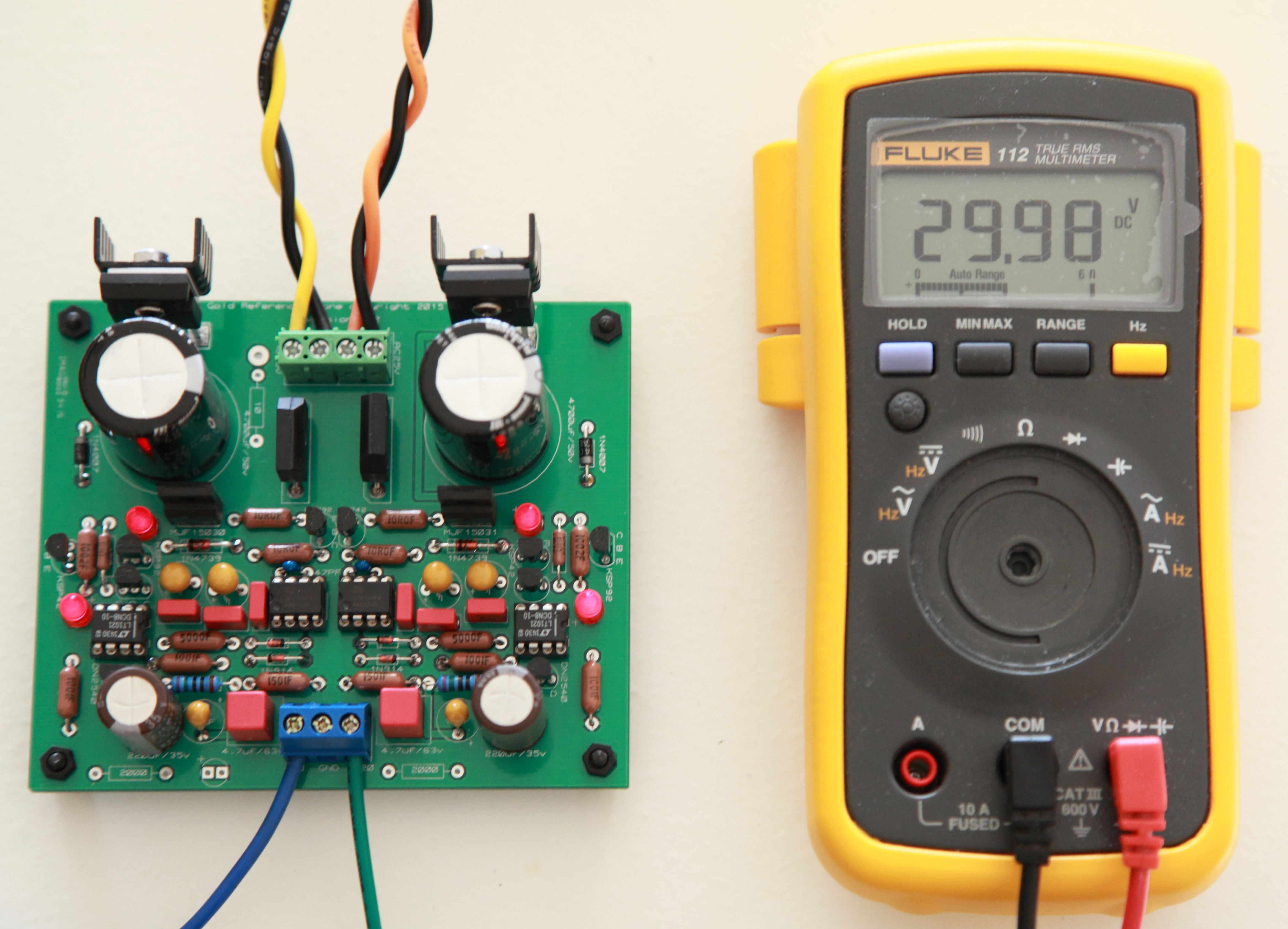
Another GoldenReference LV Dual lives! This one is, obviously, built with the the board from the Carbon GB. Had it running for 30 minutes for testing and the regulated voltage was rock steady as kevin mentioned. I hand-matched the resistors that determine the output voltage so I am annoyed that I am getting +/- 14.99VDC. I blame it on the LT1021-10 reference. I got the 0.5% tolerance ones so the result is within range (why can it not error on the other side?). I'll decide later if to go through the trouble of desoldering the change the resistors to get to +/- 15VDC. The heatsink is more for show. I plan to use this one to supply the LV for the HV Carbon. I doubt it they'll get any warmer than room temperature. Thanks Kevin for the great creation. Edit: forgot to mention, I used 2.1V LEDs and smaller bridge rectifiers. Just happened to have these parts on hand and the under-sized rectifier's spec'ed output current works for my forseable applications.

-
Hi Pars and insanity: I chose the caps in the GR LV BOM for no particular reason other than personal preference. I always liked the Silmic caps. However, the longer life spec should be a major factor to consider as well. I have added the caps Pars listed in both the Mouser project and BOM as alternatives. Size wise, they all fit the board fine. The 220uf Silmic is a bit taller.
-
Hi George: I received my Mouser order today and you are right - the QYX1H474KTP is quite large in size. I am not sure if using film caps in these positions has any benefit over using the MLCC capacitors. I picked film caps because I generally prefer them over ceramic caps. For better fitment, I updated the BOM and Mouser project to use MLCC caps (Mouser part #594-K474K20X7RF5TH5). Hope others more knowledge about the circuit can chime in which caps are better for these positions and why.
-
I updated the BOM and Mouser project for the Carbon V5 to use Vishay RN60D 174K resistors for the two 175K positions. The correct part to use is Mouser part # 71-RN60D1743F. It's a mil-spec resistor that is actually 1/2W even though it's listed as 1/4W. The previously listed Xicon 174K resistors are rated 1/4W and not sufficient for these positions. Sorry for the oversight.