mwl168
High Rollers
-
Joined
-
Last visited
Everything posted by mwl168
-
Never built the Transcendentsound amp but they have been around for a long time. AFAIK, they are OTL amps. I did build a pair of OTL mono blocks. One thing the true OTL power amps I know of have in common is that they don't like low impedance loads. So I am guessing your speakers' impedance will be a big factor how well the amp will work.
-
Were the resistance measured with the resistors on the PCB or off the PCB?
-
Ah, I read your message all wrong - was thinking down the other direction. I am devoted to keeping the overkill spirit alive... Will report back my findings if and when I try it. I looked up the TPS7A4700, indeed many layouts available at eBay and quite a few talks over at DIYAUDIO about using it to replace the Trident regulator for Buffalo DAC. It's rated at 1A max current out so will need to do one-per-channel if I do decide to go this route. Thanks all again for your help!
-
Thanks Kevin. Do you have some concern about using the GRLV for digital? To be specific, I am thinking about the possibility of using the GRLV to power the ESS9018 based Buffalo II DAC and potentially the USB receiver/reclocker/isolator too. I am expanding my Buffalo II DAC to dual mono setup and add the Amanero/Hermes/Cronus USB-to-I2S receiver. Between the 3 they may draw as much as 1.2A current. Speaking of that, really looking forward to your multi-bit DAC.
-
I have a question about the voltage setting; if I want to configure the GRLV to output, say, 5.5VDC. Is it as simple as using a LT1021-5 5V voltage reference and change the R7 and R8 resistors to arrive at the 5.5VDC output? My plan is to use the positive half of the GRLV to power the digital section of my DAC.
-
Did you try check things step by step? First check the transformer is working properly without connecting to the power supply. Then check the power supply without connecting to the amp boards and see it outputs correct voltages?
-
Oh, I guess I should have been more specific. I subconsciously separate my ES phones (007 and 009) from the dynamic phones in two different camps and don't compare them side by side. In absolute terms, my 009 and 007 setup is hands down better in every way. No comparison in my personal opinion.
-
-
Listening to the SS Dynalo and HD650 combo for the past few weeks, I certainly would not associate the term "veil" with the HD650. The friend that I built the SS Dynalo for texted me this morning and independently arrived at the same impression. What impresses me about the SS Dynalo is that it somehow manages to sound more revealing and warmer at the same time (compared to the already great original Dynalo). It also gives the HD650 bass extension I previously did not know was possible. I wonder how much can be attributed to Kevin's wonderful GoldenReference PS. Never heard the TH900. Only listened to the HD800 very briefly in an uncontrolled environment (2011 Annual DIY event at SF), its bright treble left me a scar that has not quite healed. Listened to Nelson Pass's "The Beast" driving his DIY Lowther at the same event. That's something very special!
-
-
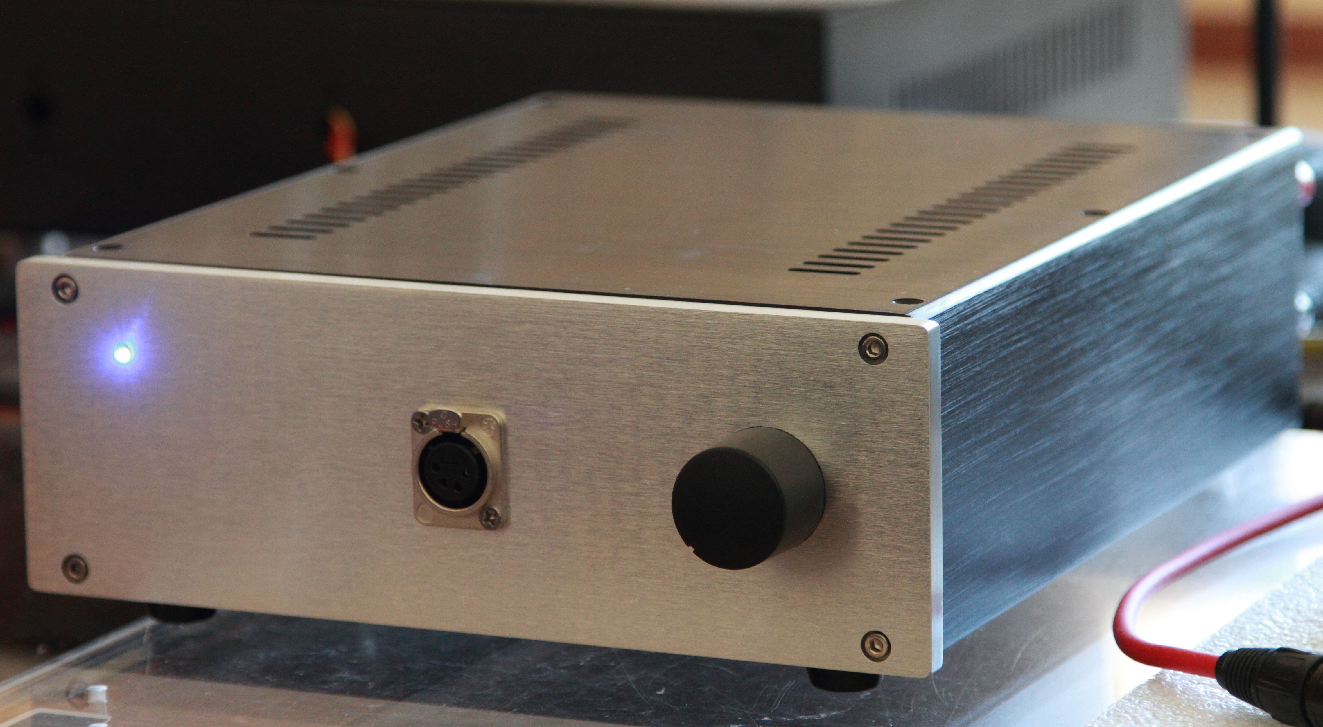
Thanks guys! John's and Kerry's builds put mine to shame. But putting an amp in a real chassis once in a while does give one a sense of accomplishment Similar experience here. I have a new found respect for my HD650 after listening to it through the SS Dynalo. I built this one for a friend to drive his HD650. After listening to the combination, he told me he is now saving to buy a HD800 to make the best use of the amp.
-
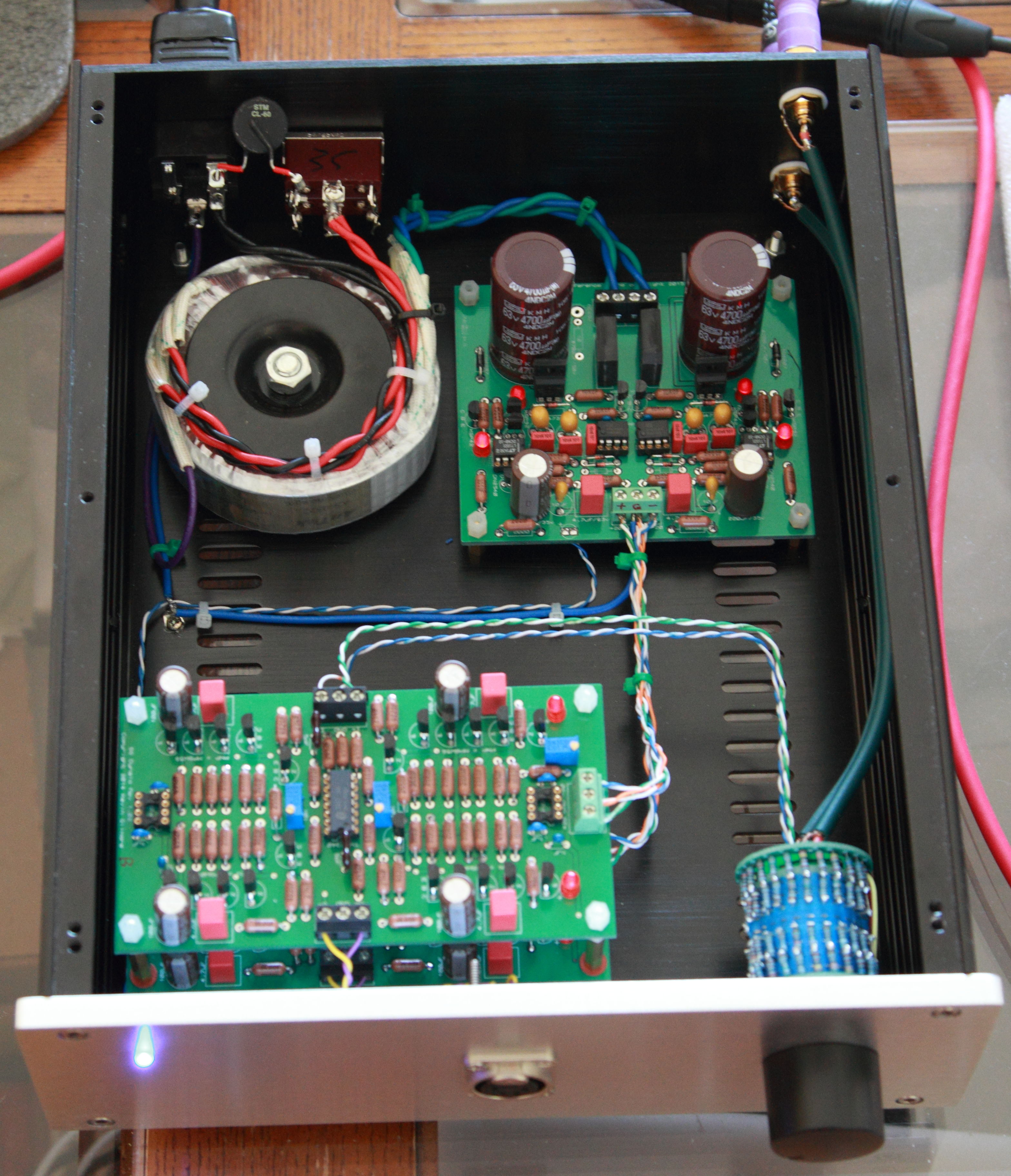
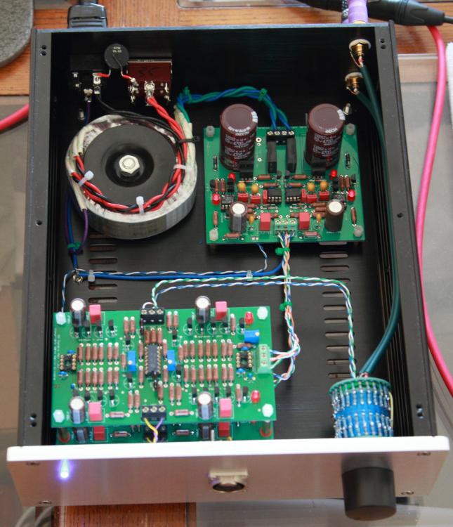
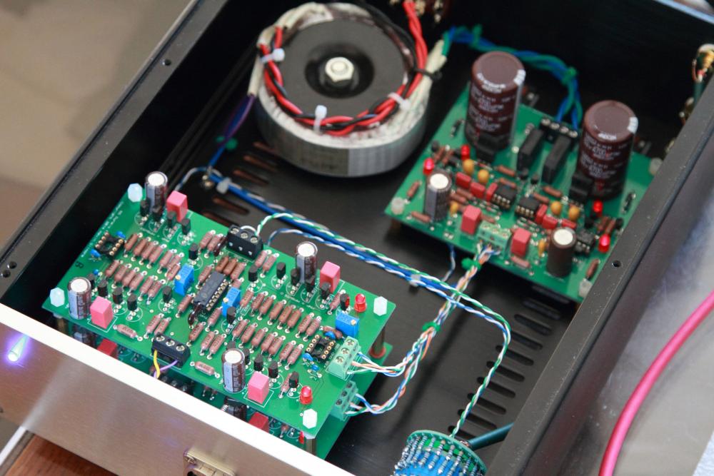
Another SS Dynalo lives. 20 VDC rails 255 235 ohm bias resistors. (see EDIT) Running single ended input and balanced output which, using the same Buffalo II/Ivy DAC, does give up something to running fully balanced. EDIT: With 255 ohm bias resistor on 20 VDC rails, the temperature on the output devices reached 95C after 90 minutes running with the chassis cover on. At that temperature the MPSWx6 max dissipation is derated to about 440mW. Even though they may be still running at the edge of their operating range, the amp sounded lean and harsh. Had to lower the bias resistor to 235 ohm which, upon fully warmed up, yields about 14mA current and the BJT case temperature is at a more reasonable 75C.

-
I cannot tell for sure from the photos you posted but make sure your pre and post regulation filter caps are up to spec. Looks like they are all 550VDC rated? I took a quick look at the Carbon amp board and I cannot think of anything you need to change going from 400 VDC rails to 450 VDC. Others might chime in if they spot someting. By the way, on my setup, I can barely feel a temperature on the PSU heatsinks after hours of running my Carbon with 20mA output setting (I think my trafo has 330 vac secondaries). The amp heatsinks are a different story, they run VERY HOT, much more so than the KGSSHV. That's another thing to keep an eye on.
-
Nice work Jose. IIRC, the dropout voltage on this regulator is about 9 VDC for my 400 VDC setup. With a 360vac secondaries you should be able to get reliable 450 VDC regulated output without issue accounting for mains fluctuation. I believe Kerry has a related post on this matter here in this thread.
-
Is the input shorted to ground and the servo engaged when you adjust the offset?
-
For my GRLV configured for +/- 20VDC regulated output, the dropout voltage was slightly below 3 VDC. As Kevin said, you need a transformer with higher voltage secondaries to account for mains fluctuation.
-
Did you measure the regulated voltage when the LEDs went dim after power up? In my experience, those LEDs close to the pre-reg filter caps only lit up when regulated voltage is achieved. Is it possible somehow the regulator sagged because the load is drawing more current than the PS can supply?
-
Actually, I read on DIYAUDIO someone did use dishwasher to clean PCB and said it works well. IIRC, it says to use the gentle cycle
-
No sure what's the currency used for the parts price. If it's USD, many of thm look way low to me.
-
I am fairly certain I used Bourns 3296W-1-502F for the 5K trim pots. The rest of the trim pots I use are all 3296W series. At a glance, I cannot make out major difference between 3299 and 3296 series. Both are rated at 1/2W. 3252 series appears to be larger in size and quite a bit more expensive.
-
Thanks for the information. I usually use a metal pick to remove the hardened flux residue followed by scrubbing with 90% isopropyl alcohol but it always leaves a residue. I am guessing it's the additive in the alcohol I use. I'll give this denatured alcohol a try.
-
Has anyone tried using denatured alcohol to clean the flux residual off the PCB? Is it safe for the PCB and solder joints? Thanks!
-
Thanks Jim. What you suggested is exactly what I did before I powered up my SRX Plus for the first time. It worked like a charm (thanks SorenB). The current will drift upwards slightly as the amp warms up and because of the variance of the parts the trim pots will likely end up at different values. The preset values I suggested in step 1 are based on actual measurement I took after the amp was stable. The good news is that once these CCS are set, they remain very stable.
-
I have received requests to share my adjustment procedures so I thought I would post it here in case others are interested. These steps are based on combination of compiling the excellent information JimL has posted and my own experience. All the trim pots except the 5K ones are for adjusting current setting of the current sources and sinks. And since they all use DN2540 which has quite a variance among samples, these setting will vary but the pre-set values in step 1 should provide a good starting point. You'll then need to fine-tune them a bit. Here are the adjustment/fine-tuning steps of the SRX Plus in sequential order: 1. Initial setup before first power on: (assuming 7mA of output current per triode of the 6SN7GTA/B) Output current source (the 4 100 ohm trim pots close to the large heatsinks): adjust the trim pots to 55 ohm if you are using 180 ohm in-series fixed resistor (250 ohm on silkscreen). These trim pots set the output current of the 6SN7GTA/B Output current sink (the 2 20 ohm trim pots between the upper 12AT7 tubes): adjust the trim pots to 12.5 ohm if you are using 75 ohm in-series fixed resistor (102 ohm on silkscreen). These trim pots set the current sink of the 6SN7GTA/B. Input current sink (the 2 500 ohm trim pots): adjust the trim pots to 410 ohm if you are using 1.2K ohm in-series fixed resistor (1.4K ohm on silkscreen) . These trim pots set the plate voltage of the upper 12AT7 (the ones closer to the 6SN7GTA/B). Adjust the 2 5K trim pots to be in the mid-point. These trim pots are used to balance the voltage of the plates of each of the two triodes of the upper 12AT7 so they are equal. The 5K pot and the 500 ohm pot will interact with each other a bit. 2. Insert all the tubes and power up the amp. If you have a variac, I recommend that you use the variac to gradually bring up the voltage for the first time especially if you are using NOS tubes that have not been powered on for a long time. 3. Check to see if all voltage (filament supplies, B+/B-, and the -20VDC) are all as expected and all the tubes lit up as expected. If everything appears normal, let the amp warm up for about 10 minutes before carry on to next steps. 4. The goal of this step is to set the output current of the 6SN7GTA/B to the desired value (7mA). Measure the voltage drop of the 100 ohm resistors of the output CCS (the 4 resistors between the large heatsinks and the .1uf/400V caps by the edge of the PCB). They should measure about 0.7VDC (0.7VDC/100R = 7mA). Adjust the 100 ohm trim pots to get the 0.7VDC voltage drop on these 100 ohm resistors. 5. The goal of this step is to set the output current sink to 17mA, 3mA higher than the output current. Measure the voltage drop of the 100 ohm resistors of the current sink (the 2 resistors between the 20 ohm trim pots and the single .1uf/400V cap between the two lower 12AT7 tubes). They should measure about 1.7VDC (1.7VDC/100R = 17mA). Adjust the 20 ohm trim pots to get the 1.7VDC voltage drop on the 100 ohm resistors. 6. The goal of this step is to set the two plates of each of the upper 12AT7 to be equal and about mid-way between B+ and ground. So if you are using B+ of 360VDC, the mid way is 180VDC. First attach the DMM probes to each of the two .22uf/1000V coupling caps where they are connected to the plates of the upper 12AT7 and measure the DC voltage between them. (in my case. I purposely left the leads of the coupling caps sticking out a bit so I can clip the DMM probes on them. With the 5K trim pot set at its mid-point, the measured DC voltage between the two plates tells you how well matched are the two triodes of the 12AT7 tubes used. If they are well matched it should be within 5 VDC or so. If it's more than 20VDC you may have problem**.) Adjust the 5K trim pot so the measured voltage is close to 0VDC. Next, move one of the DMM probes and clip it to the power ground (leave one probe still connected to one of the coupling caps) and adjust the 500 ohm trim pot so the measure voltage is about 180VDC (half of the B+). The adjustment of the 500 ohm and the 5K trim pots will interact with each other so you'll need to go back and forth a bit. 7. Let the amp warm up for another 15 - 20 minutes for the tubes to reach their stable operating state then repeat the adjustments again. Measure the balance via the headphone jack like you do with other Stax amps. If the two triodes in each of the 6SN7GTA/B are well matched you should see around 1 or 2 VDC or so. And this is perfectly fine. 8. Measure the offset via the headphone jack like you do with other Stax amps. Adjust the 20 ohm trim pot (output current sink) to bring the offset as close to 0 VDC as possible. 9. Assuming all adjustments are carried out without problem, you are done and ready to listen to music now ? This is an all tube amp without servo so the offset and balance etc. will never be spot on and will vary and drift a bit every time you power on the amp. That’s to be expected. 10. There is an optional step which I have not done myself - you can adjust the 2 100 ohm output CCS trim pots to bring the balance of each channel to 0 VDC. I have not felt the need to do it (maybe I got lucky with the tubes I have). If you choose to do so, try to adjust both trim pots in a converging fashion instead of adjusting only one of the two pots. You'll also need to "coordinate" this with adjusting the 20 ohm pot in step 8. Hope this helps. JimL and others please chime in and correct me. ** In my experience, with the 5K trim pot centered, if the voltage difference between the two plates of the 12AT7 is greater than 15VDC or so, you should still be able to adjust it to 0 VDC but you may encounter problem with buzzing noise. You can move the 12AT7 tubes around to minimize this voltage difference. In my experience, it's more important to have the lower 12AT7 (the one closer to the 5K trim pot) well matched to bring this voltage difference down.
-
Thanks Kerry! LT1021 it is. By the way, apologize for cross-posting but I tested my GRLV tonight and for regulated +/-20 VDC output, the drop out voltage is about 3 VDC (slightly lower actually).