mwl168
High Rollers
-
Joined
-
Last visited
Everything posted by mwl168
-
For more than a week now, I have not been able to save edit to a post or PM using iPad/Safari. No problem submitting new post or sending PM. Anyone else experienced similar issue?
-
Thanks JimL.
-
Many thanks for the detailed explanation JimL. Very much appreciated. I should have read your posts more carefully. One more point of clarification; based on you post on May 22, 2015 on the SRX Revisited thread where you explained the input stage in detail, do I understand correctly, that the "lower tube" refers to the 12AT7 that accepts the input and the "upper tube" is the 12AT7 that drives the output stage? Thanks!
-
Hi JimL: I am building the SRX Plus and have been thinking about how to adjust the completed amplifier for optimal operating condition. I compiled the following procedure by reading and parsing through the information in your earlier posts on the SRX Revisited thread. Can you verify and advise if it’s correct? Set input stage current source to about 1.1 mA by adjusting the 500R pot and measure the voltage drop of the 100R resistor in series between the -20V input and the 500R pot. (Assuming 300K plate resistor for the upper 12AT7 as marked on the board. If you use 250K plate resistor then it should be 1.3mA) Set the output current load for 7 mA by adjusting the 100R pot and measure the voltage drop of the 100R resistor in series between the 5.1K output resistor and the 100R pot. Set the output current sink for about 17 mA by adjusting the 20R pot and measure the voltage drop of the 100R resistor in series between B- and the 20R pot. Set output balance close to 0 VDC by adjusting the 5K pot. Set the INPUT balance to 0 VDC by adjusting the 5k pot. You are trying to get the upper 12AT7 plate voltages to be the same. An easy way to do this is to connect your meter leads between the "bottom" of the two 12AT7 plate resistors and adjust the 5k pot to zero volts. Set output offset close to 0 VDC by adjusting the output current sink pot (20R). Also, below is a quote from your post on May 6, 2015. Can you advise where and how this fine-tuning fit in? Thanks! “…the published schematic has adjustments in the output current loads, this can in fact be used to vary the cathode-to-plate voltage individually for each output section by slightly altering the current running through each section. The concept is, start with the output current loads fixed, adjust the cathode current sink to approximately zero the output plates, then vary the current loads to adjust the offset between + and - voltages for each channel. The three adjustments are interactive, so, it would probably be best to adjust one of the current loads to partially decrease the offset, the adjust the other in the opposite direction to further decrease the offset until that is balanced, then adjust the current sink to zero both plates…” EDIT: procedure corrected based on JimL's response in the next post where he also explains how to adjust for output balance if necessary.
-
I do know there is heaven in DIY.
-
I am fairly certain I used kgdynalobal5.zip from Kevin's site back in January 2015. On the silkscreen it says version 1.02. However, the current kgdynalobal5.zip on Kevin's site has a June 2015 date and the version is 1.1. IIRC, Kevin fixed an issue of the board on this version - this information is somewhere in this thread.
-
The last board run I did was the TO92 version and sorry I don't have any spare boards available. The boards I had were from SeeedStudio, 1.6mm/2oz. As Pars said, they work fine and the cost was reasonable.
-
Too early to tell. Need to spend more time with the SR-009 and run it through the different KG ES amplifiers for me to get a good handle of its sound. I was just surprised by the margin of difference between the two - wider than I have expected.
-
Just received a pair of SR-009 tonight. Serial No. SZ9-34xx. Running it through my HV Carbon. This thing sounds different than my 007 MK 2.9.
-
Thanks Kevin. I experimented with the opto server tonight (this time with the OP27 in place) and here are my observations: Without the servo jumpers in, I first adjusted the offset of both boards to be about +18 VDC at cold start, measured between the + output and ground (this applies to all subsequent measurement). I then inserted the jumpers and powered on the Carbon with opto servo now engaged. The offset on one board measured -2.5 VDC right from the start, it dropped to about -1 VDC after 5 - 6 minutes, from there it hovers around -0.9 VDC, drifting about 0.5 VDC or so up and down. I measured again at 20 minutes and then at one hour marks with same results. At the one hour mark, I adjusted the balance from around 2 VDC to within 0.5 VDC (absolute value). This brought the offset to hover around -0.1 VDC. The other board exhibited similar behaviors but started with and ended at lower offset voltage. (Without servo, this board has always had lower offset and balance compares to the other one.) It appears to me that the opto servo is working and it's effective from the very start although it does take about 5 minutes or longer to reach the lowest possible offset voltage. As I have mentioned in the past, the Carbon, without the servo, is very stable to start with. It seems to me the main advantage of the opto servo is to keep the offset at a low voltage from the start and settle it down faster. Without the servo, my Carbon typically takes between 15 - 20 minutes for the offset to settle.
-
-
Thanks Congo5. I was wondering the same thing (if OP27 is needed for the opto servo to work) after reading the schematic. I will install OP27 and give it a try. One question, does the output need to be as high as 20V for the servo to work? Shouldn't 5V or so be enough for the OP27 to sense the differential? From the get go with the offset and balance pots centered, my Carbon has not seen higher than 15VDC offset.
-
-
Thanks all for your kind consideration and offer. We are all fine. Also, as of today, all boards have been shipped including the international-bound ones. Happy building!
-
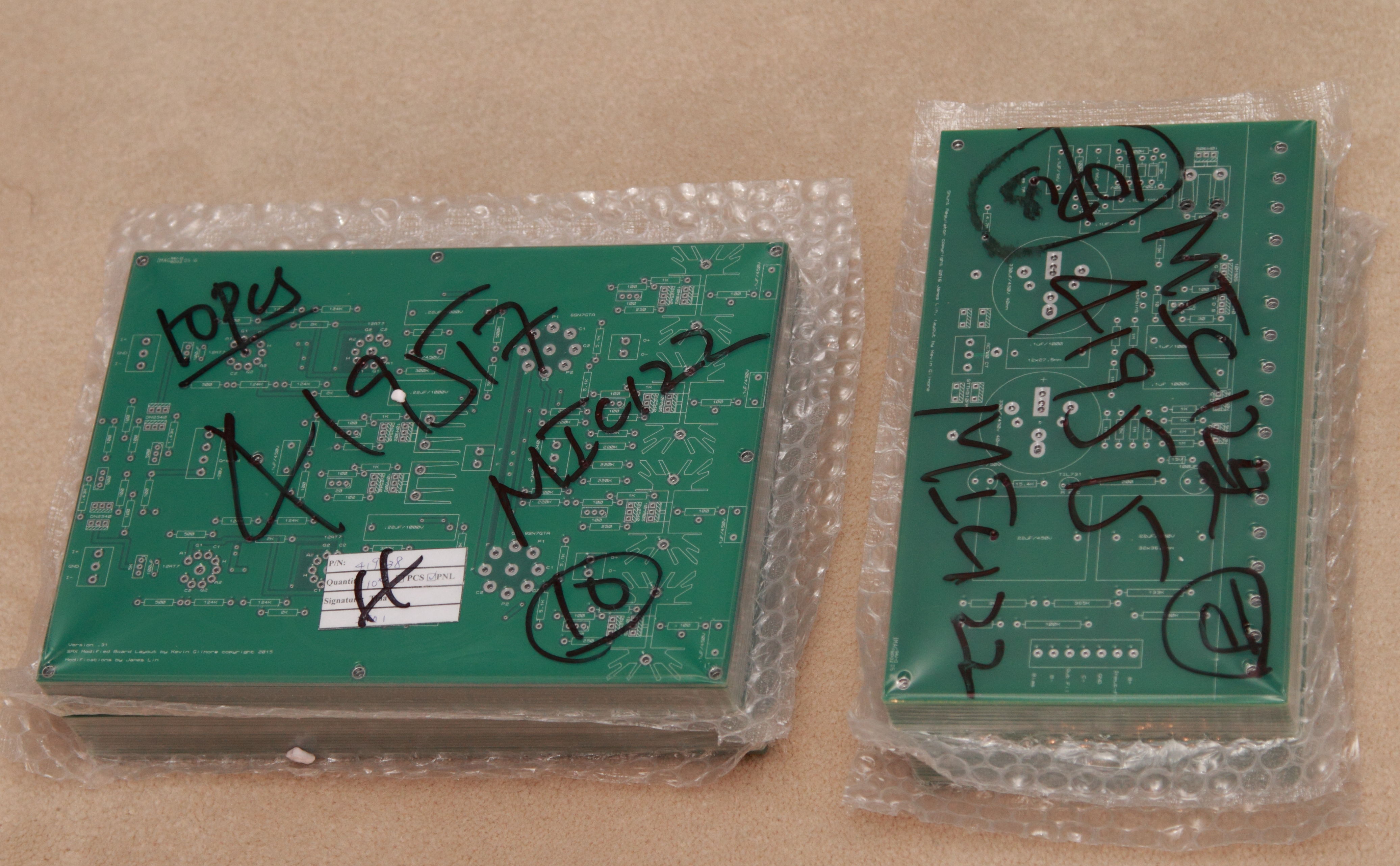
Ah-Oh! I goofed. One of the SRX amp boards from PCBNet has an obvious cosmetic defect at the left lower conner where the version number, etc. is silk screened. I have intended to keep it for my own use but in the process of taking a photo of the defect to inform PCBNet and packing the boards for shipping, I must have shipped it to one of the GB participants by mistake. I apologize. Can the unfortunate recipient of this defect board post or PM me so we can discuss what to do about it? PCBNet has informed me they did find a spare that they can send me for replacement but unfortunately we'll have to cover the shipping cost. Given the circumstance I had agreed to simply let PCBNet include this replacement board next time I order boards from them.
-
All US bound boards were posted via USPS Priority Mail today. I have the quotes from USPS for international First Class Air Mail shipping based on weight today. I will PM each individual GB participant with your shipping charge. Be prepared for a bit of unpleasant surprise - USPS raised the price of its services on January 17.
-
JoaMat is correct - MPSW06 pinout is different than the 2SC1815.
-
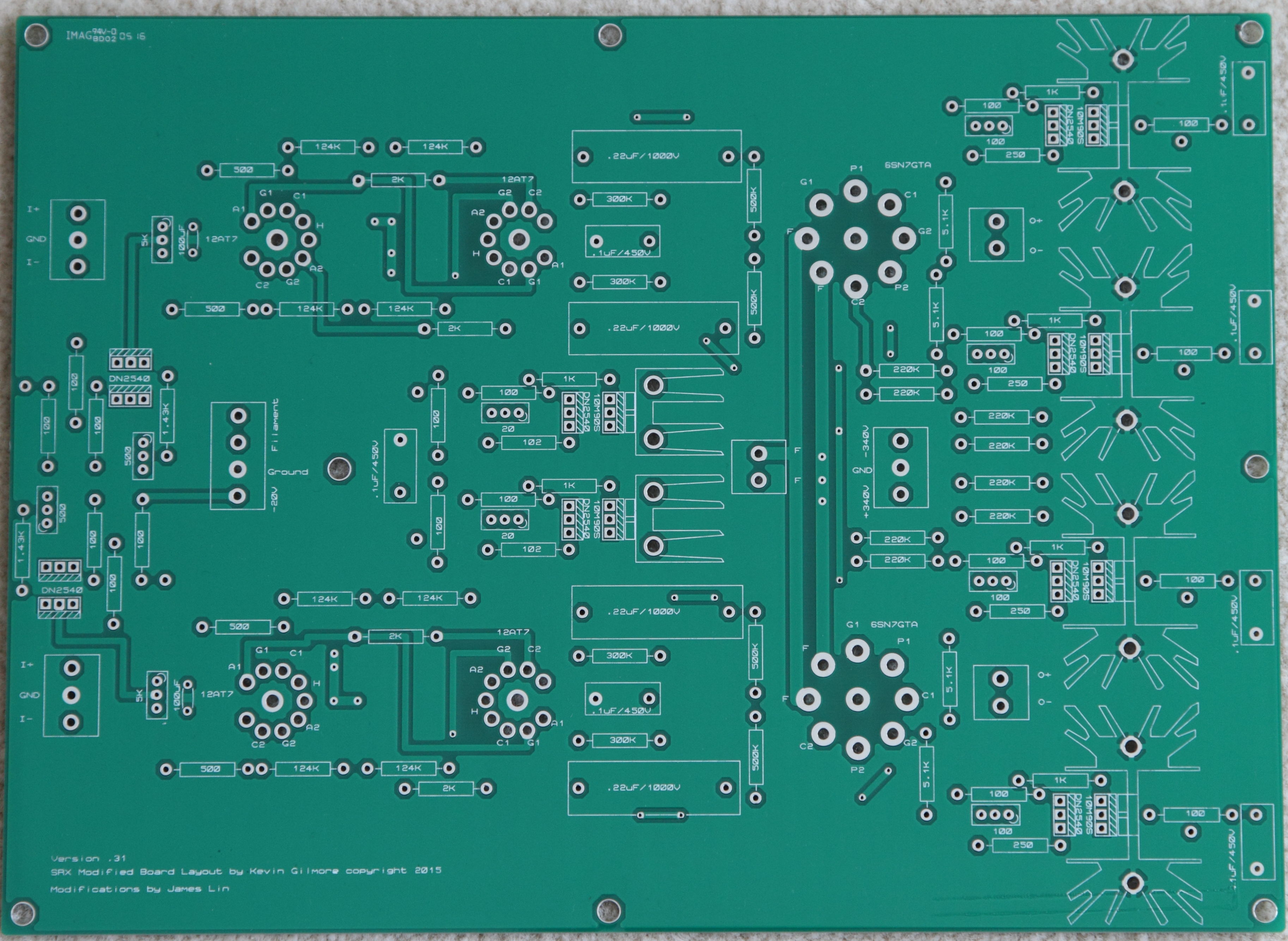
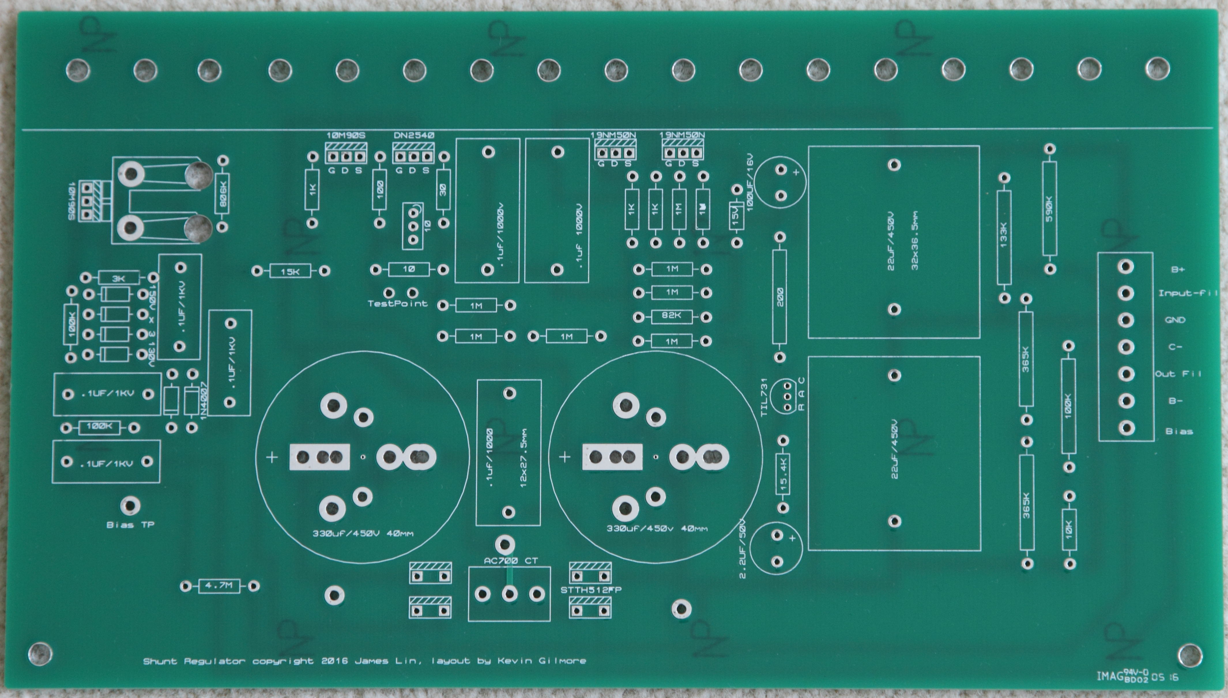
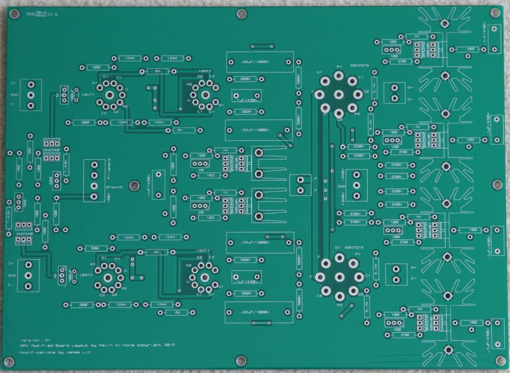
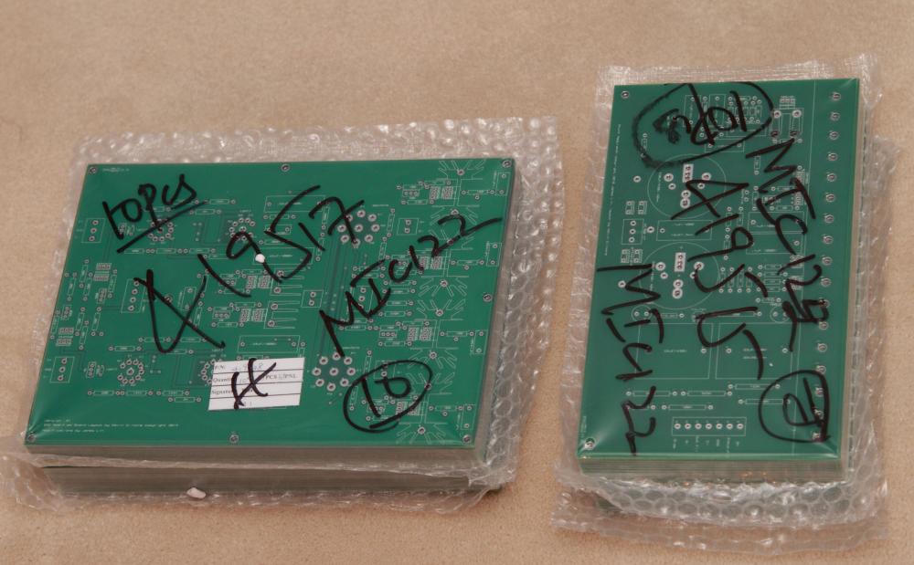
Better quality photos of the boards as promised.
-
A bit more information will help others to offer their assistance. What version of boards are you building? What voltage PSU are you running? What's the offset and balance at cold start and are they responding to adjustment? A few good resolution photos of your boards will be very helpful.
-
Got home very late tonight to find the PCBNet package sitting in the foyer. Delayed one day by the snow storm that hit upper Midwest Tuesday. Quick visual inspection of boards shows typical quality fabrication as can be expected from PCBNet. These 2mm, 4oz boards have a hefty feel to it. Will post better quality picture this weekend under daylight. Shipping will start next week.
-
FWIW, I use a 200VA transformer and run my HV at 15mA output current. I use NTC thermistor on the prmiary of the transformer and use 3.15A fuse. It has been working fine for a few months. I have not gotten around to try smaller fuse yet so it provides proper protection in the event of faulty operation.
-
I did an experiment earlier today - changed the bias resistors on my off-board KGSSHV to run at 15mA per output devices. It has been running continuously for 5+ hours and it appears to be working fine. I am running 415VDC rails PS. As far as I can tell by using an infrared thermo gun, my puny heatsinks are measuring around 50 C or so. It's a bit difficult to get good measurement of the case temperature of the 2SC4686A because how they are mounted to the heatsinks but my best guess is around 60 C, again, based on the infrared thermo gun reading. That's pretty close to the 7W dissipation limit at 60 C as stated on the 2SC4686A datasheet. For long term peace of mind, I will be looking for a chassis with ample heatsink for my HV.
-
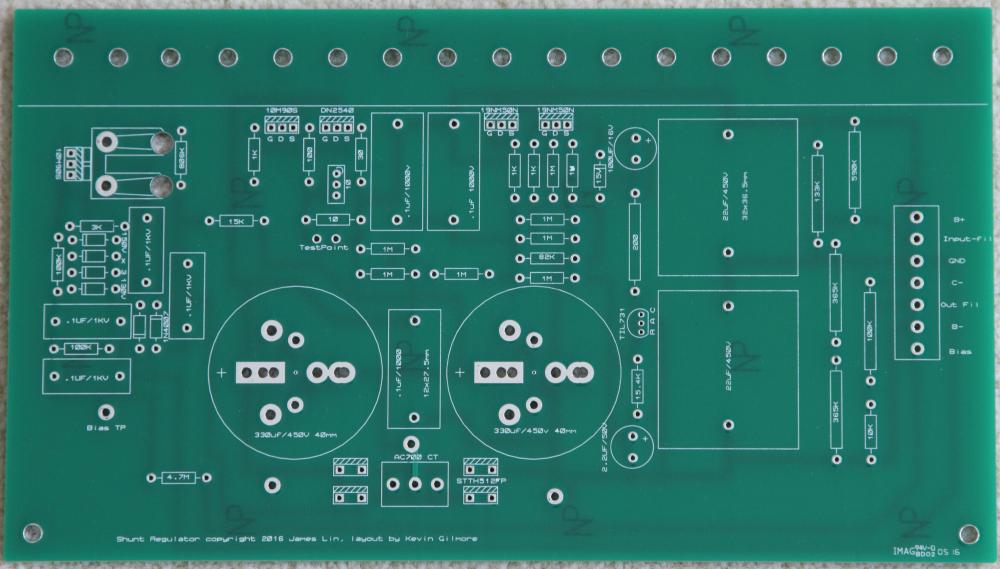
I really like the idea of including the 330R + .022uf snubber on the board.
-
A variac will be your friend in this case. I bought one and have found it to be a valuable tool to have especially for building and testing these high voltage circuits.
-
This may not explain the zener problem, but what shoulder washers are you using for the 10M90S? There are some discussions over at the KGSSHV thread on using washers that prevent shorts between the screw and the tab of 10M90S for high voltage applications. Basically, the "tube" of the washer needs to be long enough to extend into the insulation pad below to prevent accidental shorts.