G600
Returning Member
-
Joined
-
Last visited
Everything posted by G600
-
Yep, i found a small 30va rcore with dual 15v secondaires. Will mesure if it fits. Half the price of the trafo rework, not mentioning the lead time. But i still feel dumb...
-
I'll see what Mr Monaghan can do then...
-
OK, there is the culprit. So I jumped both feet into Lil Knight's error (boards markings, etc...). Would you share a solution, other than reworking the secondary ? I could put 63V caps, but max DC for the 7X12 is 35V...
-
Today I triggered my PSU. Before I had a chance to measure high voltages, I heared something boiling. The two 4700µF were hot and their tops are now convex. Sounds like an overvoltaged cap, right ? Maybe the center tapping is confusing me, but why a 25v rating for those ? Isn't the 30-0-30 rectified to 42v ? This way 50v seems to be the minimal requirement... Any thought ?
-
Pretty damn scary ! But start with serious soldering. Like cutting the sand's legs. Like not putting that much solder (2nd picture, at the 10M90S). And source genuine components from reliable sources, even if it can be expensive.
-
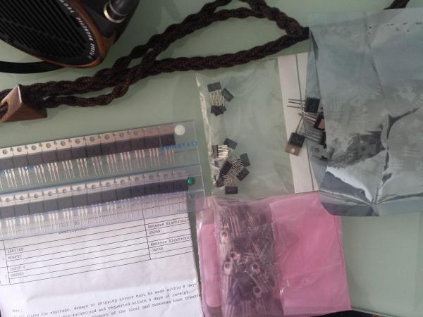
I have stuffed my amp boards with them. I'll let you know how they react.
-
-
Kerry, brilliant work, cheers ! Dunno why, but SMD for high voltages (when possible) seems to be safer to me. Less chance of badly bent things, and cold solder joints. But I'm uneducated.
-
What do you think of its sound ?
-
-
I was sure there was a technical explanation. I started to salvage the traces, and copper it is. 4 oz. Damn hard to get rid of. Those boards are borderline too much overkill.
-
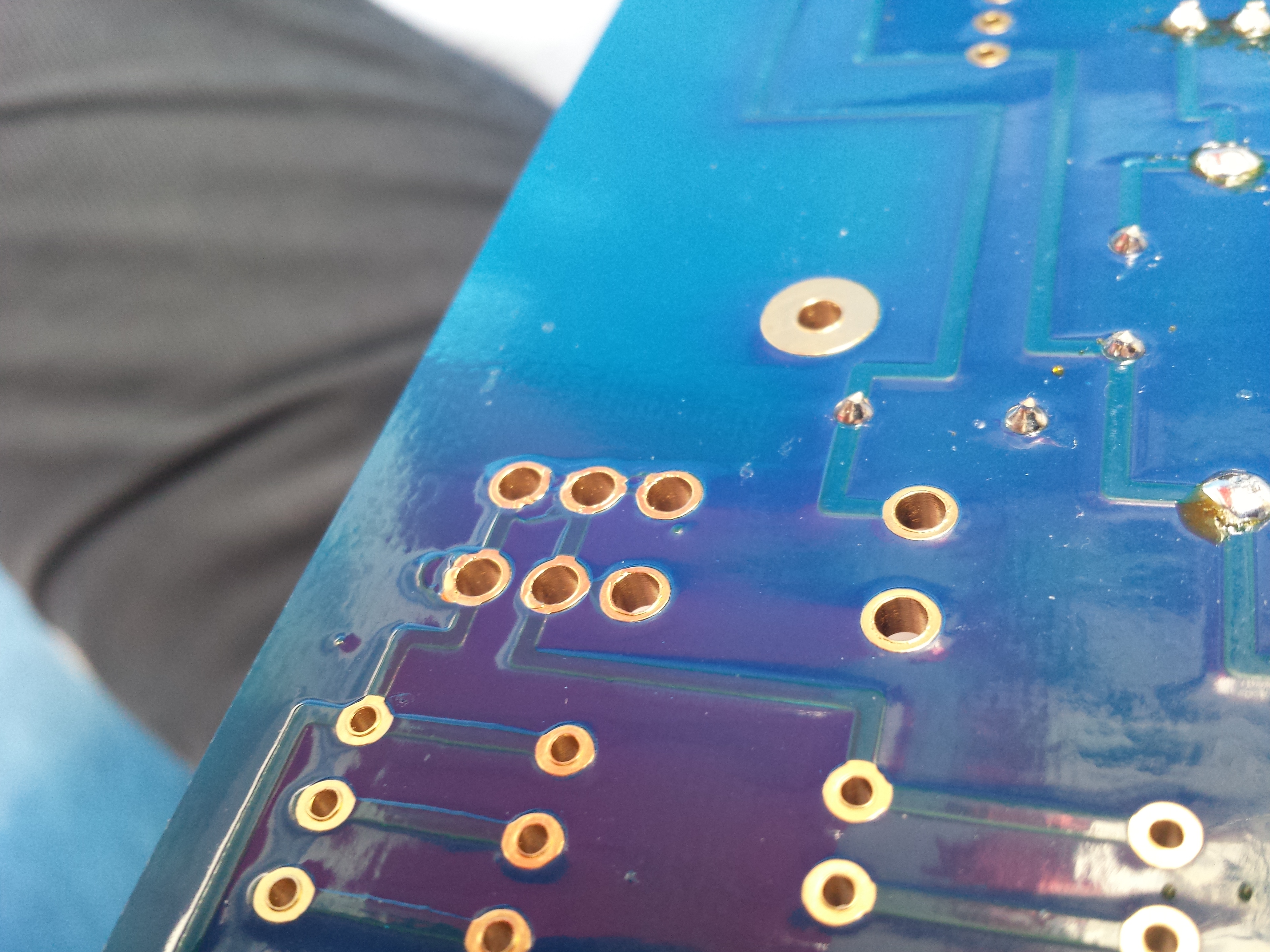
You can clearly see the "leakage", but at a second look you may peek traces between second and upper third row.
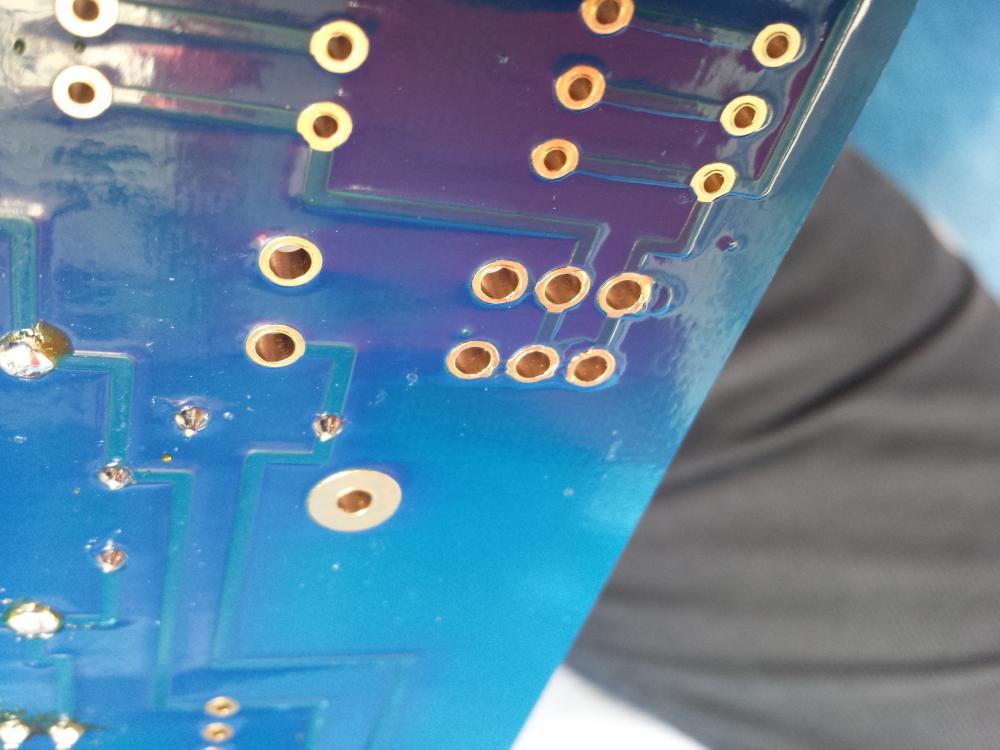
-
I may post a picture if I can catch it with my crappy phone. It looks like leaking copper around the holes, but I can also see direct connections between adacent holes.
-
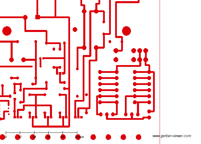
Yes, this is the only area of both boards with bad looking traces around the holes,making undue connections. Think I'm going to salvage them, helped by the gerber's bottom copper traces.
-
Yep, a shrunk blue board. But the one I have on hands have connection between each and every one of the 6 holes, both vertically and horizontally. Of course nothing is soldered to it yet.
-
Yes I did compare, but it's suspect.
-
While going very slowly, I inspected my blue board PS and have a question. It looks there is a mistake on it at filament relay. Are the 3 lower rows of pads supposed to be connected together ? I have continuity from a row to another (except the upper row obviously).
-
So classy, thank you !
-
Big children are happy with weired toys... At least no Lenesas here ! (always crappy pictures with me)
-
Any finished system here ? I also would like to know if mpsa are OK for the ubal to bal boards ? And what is the proper way to use them with dynalo mk2 ? Thanks
-
-
Just build one yourself ! We are waiting for your thoughts and tweaks
-
It looks good all SMT. And quite straightforward. I have just finished Sjostrom's Qrv-08 today, which is trickier with it's massive PS.
-
Texas components make them to order with no additional cost.
-
Texas components make them to order with no additional cost.