rumina
-
Posts
62 -
Joined
-
Last visited
Content Type
Profiles
Forums
Events
Everything posted by rumina
-

and now for something completely different part 3
rumina replied to kevin gilmore's topic in Do It Yourself
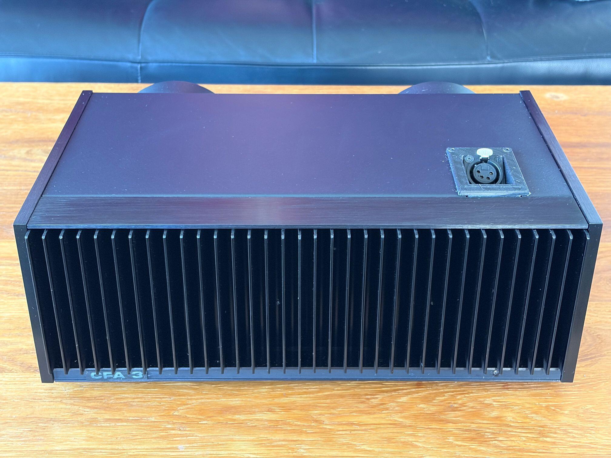
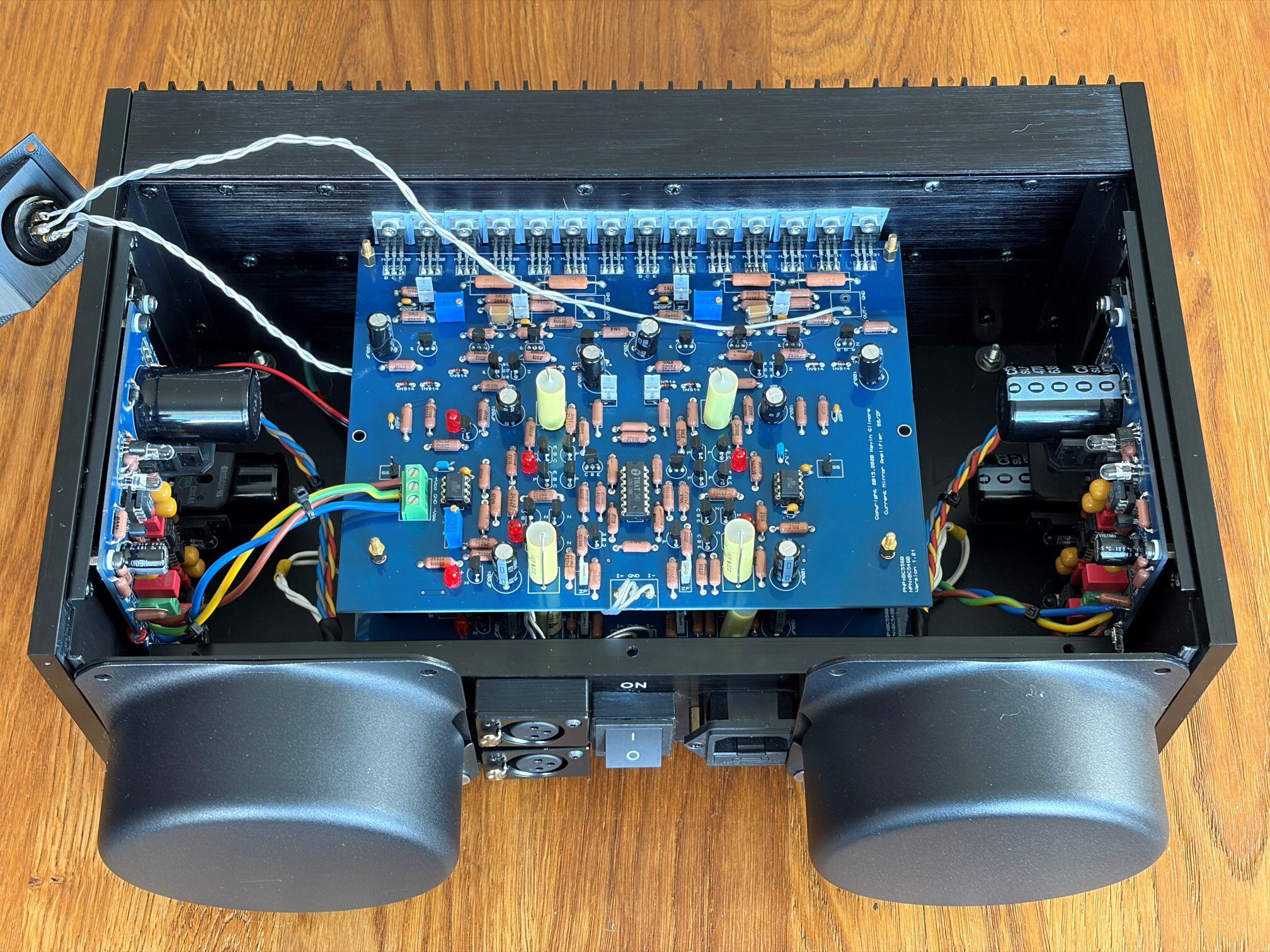
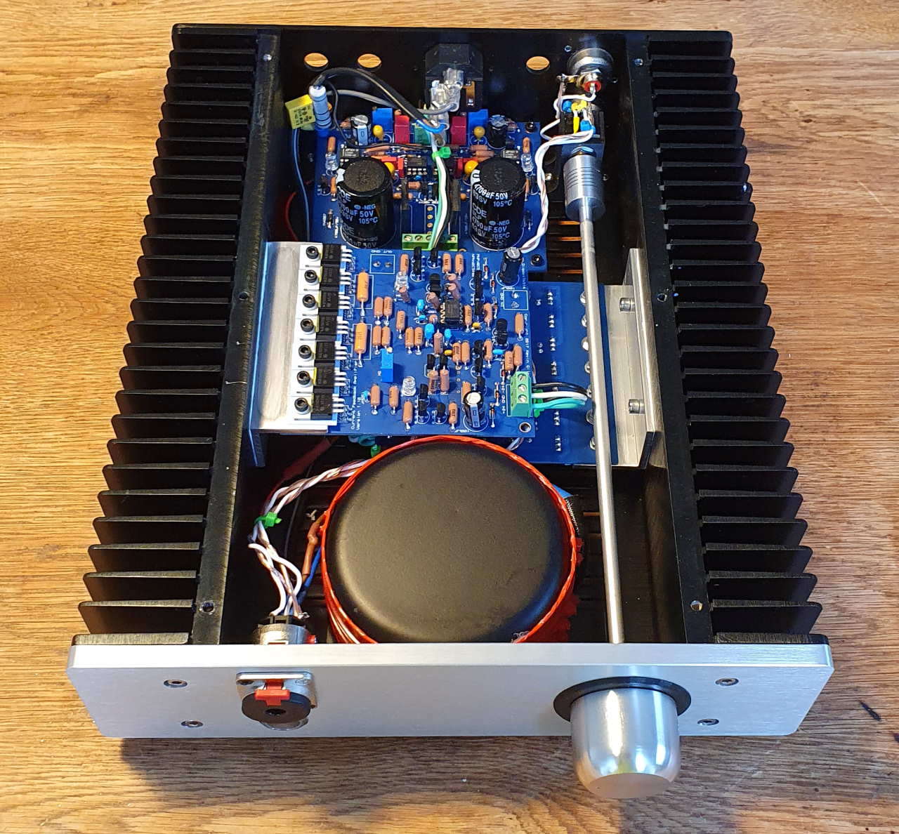
finished my cfa3 this week, thanks kevin gilmore for the desing and the support from the forum members. running on +-30v with moderat bias, changed the gain resistors to 3.2k for lower gain. needed some 3d printed parts so that all fit fine, a cfa3 in a quad 405 chase. no pot this time, i use a dac with volume control or a preamp. after all amps i build i think the best solution for a 1 case build ist mounting the trafos outside in vertical position, absolut no magnetic hum inducted. i also added grain oriented metal band around the trafos inside the trafo cases.
-
and now for something completely different part 3
rumina replied to kevin gilmore's topic in Do It Yourself
thank ang728 for the info, then im ready to order parts 🙂 -
and now for something completely different part 3
rumina replied to kevin gilmore's topic in Do It Yourself
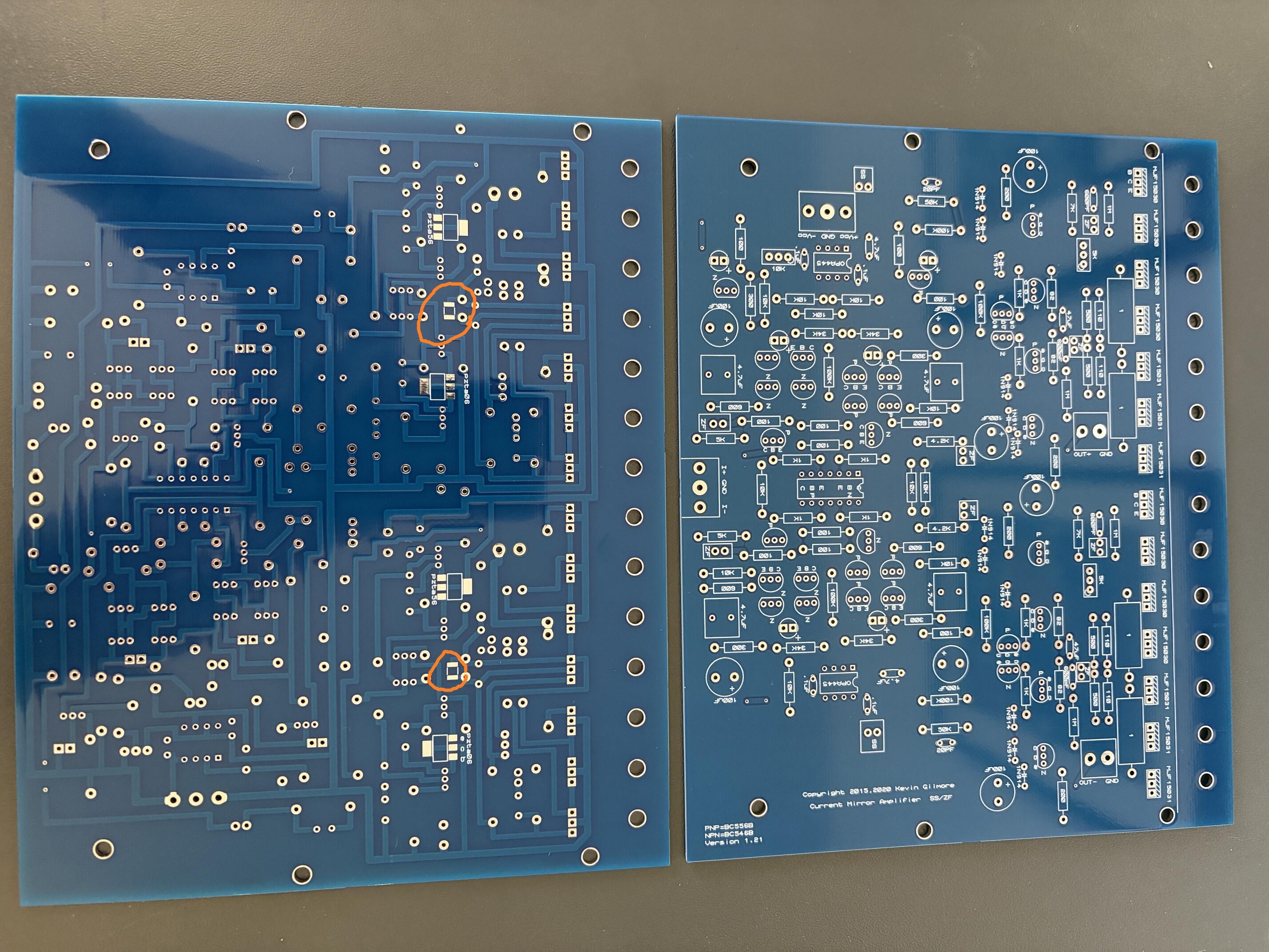
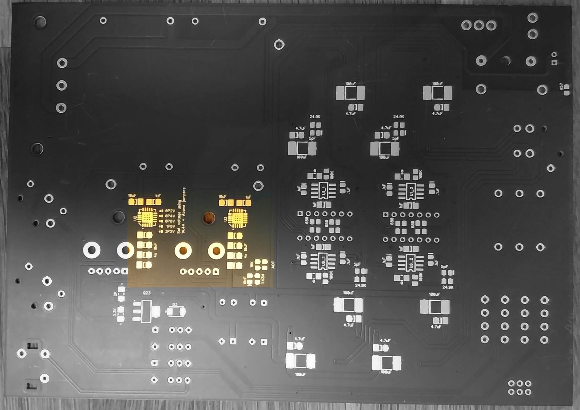
i habe some current mirror amplifier ss/zf version 1.21 here that i like to use for the amp build. may i ask about two points on the underside of the board (orange marked) look liks place for a jumper on the front siede the are between the two 82ohm resistors. are they for jumper and/or what are they used for. thx
-
and now for something completely different part 3
rumina replied to kevin gilmore's topic in Do It Yourself
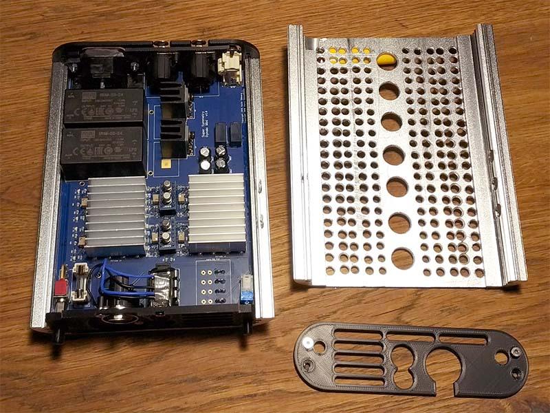
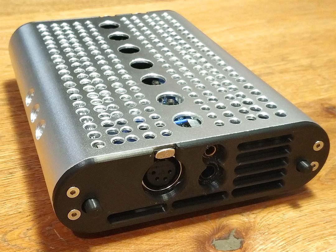
it's a BRZHIFI BZ2607 case from aliex..., size is 260*311*70mm. i have to many silver boxes so i like compact sizes even if the layout isn't perfekt. the trafo is a 100va /24volt from triad magnetic VPT24-4170 (mouser), with a bias of 200ma the amp needs only around 40va so a lot of reserve here, next time i would chose one that is a bit smaler. -
and now for something completely different part 3
rumina replied to kevin gilmore's topic in Do It Yourself
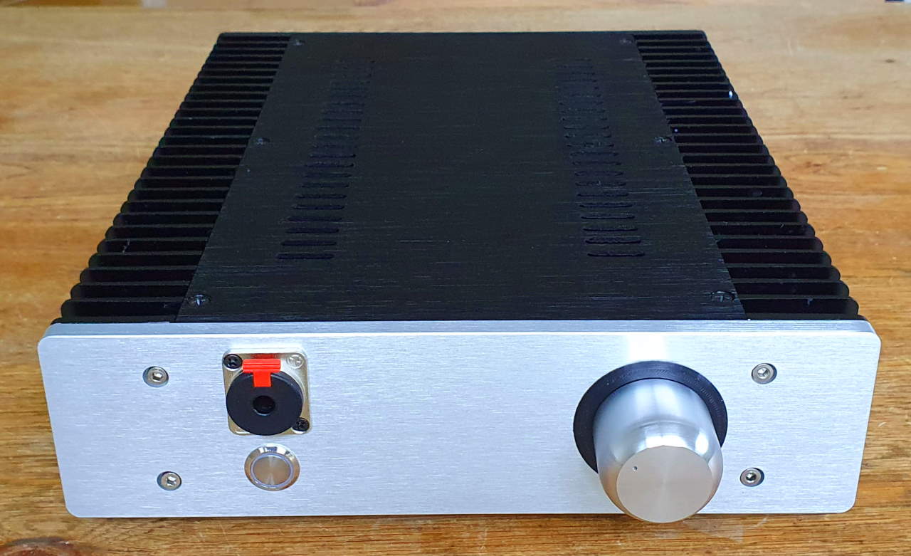
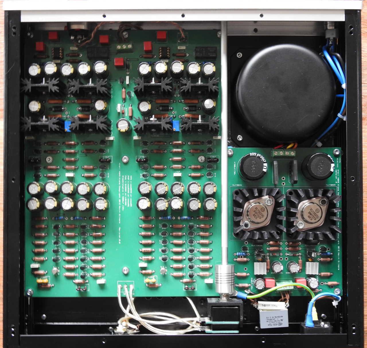
finished today my cfa2, was a trouble free build beside that i like small case (think is a tetris disorder i caught in my teenage years ;-). once again, these trafo covers look nice but the shielding effect is near zero, to get ride of a small hum i needed to add some grain oriented bands. heatsinkt of the case seems a bit overdesingned, gets only a bit warm. offset without servos was surprising low at around 10-15mv, could use nice matched mje15030/15031 from my previous dynahi project. the amps sounds very nice, one of the few amps that are neural and speedy that i like, really a "wire with gain" type of desing. thanks a lot for the design kevin gilmore and all of you for the help from this forum :-).
-
Kerry Design mini GRHV\GRLV and JoaMat mini T2 Group Buy
rumina replied to mwl168's topic in Do It Yourself
my pcbs arrived today here in switzerland, thanks for the work 🙂 -
Kerry Design mini GRHV\GRLV and JoaMat mini T2 Group Buy
rumina replied to mwl168's topic in Do It Yourself
payment sent, thanks -
Kerry Design mini GRHV\GRLV and JoaMat mini T2 Group Buy
rumina replied to mwl168's topic in Do It Yourself
i go for partial assembled boards, thanks for your work 🙂 -
these cover are mostly cosmetic but i like to use them, the only shield a tad vs grain orientated metal or mu metal. place the trafo near the big transistors with heatsink and you have a silent amp like in this pic (the 3th i made). my first version had some inducted hum because the trafo was on the other side near the small transistors. good luck with your build :-).
-
nice to see your success, it's the amp i like a lot with my power hungry magentoplanar headphones. after the that340 i tested the trendsetter lsk489/ls689 but at the end i enjoyed the 2sc3381/2sa1349 the most, quite shure that with the 2SK170/2SJ74 this amp performs superb. let us see the amp when it in its chase ;-). well done
-
oBravo Ra C-Cu
-
superb that are some nice amps :-), well done
-
Kerry Design mini GRHV\GRLV and JoaMat mini T2 Group Buy
rumina replied to mwl168's topic in Do It Yourself
great please add me with: 2x grhv, 4x grlv78xx, 4x grlv79xx, 1 main board, 1 mini t2 thanks -
if the case is high enough you can try to mount the transformer standing up, base parallel to the back plate (or mount it direct to the back plate). i would remove the screw of the trafo, turn it up whitout fix mounting to test if the hum is less (if less thats a least one part of the problem).
-
this is the case i used: https://de.aliexpress.com/item/143-40-4-180mm-WxH-D-aluminium-elektronik-pcb-geh-use-6063-extrusion-fall/32857644347.html?aff_platform=api&cpt=1549182007927&sk=ZVxRRvI&aff_trace_key=807df99551d348b39035d168c5f73204-1549182007927-05033-ZVxRRvI&terminal_id=1183572cd19e4eb0be580194ccaeaa77 the pcb slides in the grooves (some tap around the edge for isolation). but you need make some place for the top cinch connector (grind the topcase a bit with a dremel or similar tool, shorten the silver latch). then do the same thing for the two caps underneat he pcb, they need 2 mm more space on the side of the pcb. now you can slide in the pcb from the top (not sliding the pcb in) in the groove opposite the caps underneat, push down and the pcb holds in place. for the topcase to fit you need to grind down the ac socket a bit, easy done with a dremel. due the case is a tad longer then the pcb i printed two case holder plates that hold the pcb in place, so you can also use the orginal alluminum plates, sadly the topplate is realy thick and i was to lazy and printed the two top plates also. i attache the freecad files and stl files so everyone can use them (missing are the holes for the pot/4.4mm plug and vents if you need them, easy to add). the case is thight but works fine with some work and patience, take care of the heat, venting is not easy for this case. smd_dynalo_roundcase_front_back_v2.zip
-
my two smd amps with bivar leds running at 20 volts and led vf 1.71 volt, i also would go down a tad with the bias to around 15ma. second one (the one in your list) with 16.5 ma / 81c max after 2 hours - ok but on the edge. so i would use next time r14/29 around 210 ohm for bivar leds and 402 ohm r1/r3. this is my second one, a lot of holes top and bottom, printed front and rear, whitout potentiometer, additional 4.4mm output. i use this one for travel together with a dap: my first amp only with small heatsink in the group buy case (with r14/29 240 ohm) was around 100c max and even discolored the pcb a bit. more holes (best over 4mm diameter) and a heatsink lowered the temp to around 80c. if they get hot the bias rise quite fast even when the start bias is relative ok or low. but i love them, like the sound better then my big dynalo, i now use on both from trendsetter - linear integrated systems matched lsk489 lsj689 jfets.
-
CLOSED: Alpha/Song Huei Potentiometer Group Buy and TKD Attenuators
rumina replied to cspirou's topic in Do It Yourself
may i ask i someone has a Song Huei 10k quad pot 2142 left from the group buy. i have a older smd dnynalo pcb that i whant to use, thanks far a short pm ? -
@pars some measurements for my finished second smy dynalo - found a good combination for the bivar leds. amp gets stable after 30 min (with heatsink mounted), hottest parts are the small transistors at ~81 c, the regulators are ~75 c. heres the data: D1 / D2s = Bivar SM0805HCL R14 / R29 = 226 ohm R1 / R3 = 402 ohm 330mv / 16.5 ma hot 205mv / 10 ma cold my first dynalo has R14 / R29 = 240 ohm and was running to hot, could bring the heat down with some heatpipes attached from the heatsinks to the case (power consumption stable at 25-26 watt). the second one runs at 20-21 watt without heatpipe. i also change the trafos to the mean well IRM-20-24, same size but 2x21.6w, even a tad cheaper.
-
great, thanks pars ? allways something new to learn
-
had this question in my mail, so as reference for users with offboard regulator, these parts in the square are not needed:
-
Thanks for the measurements - similar then mine ~26 watt with open lid, will rise a little with closed lid but i thinks thats should work fine as mine (i use the group buy case). do you mean rms in terms of pmpo (or pure mystic power output ? )? then no - it's simply the overall power consumption of the amp. rms would go something like= max watt out transformer - powerloss transformer (here 18%) - powerloss regulator (how efficiency are those regulators?) - powerloss transistors/cricuit design. i don't like these rms values, take a big switched power supply, add some beefy mosfet and you get big fat rms values, sounds like shit and do to boooooommmmmm
-
Sounds ok, i use 20-30 % efficiency for class a amp after power supply. but that is a crude gess, good to take the magic appart from 20 watt class a amps with a mini powerbrick. the two mean well irm-15-24 trafos have a build in protection for short, overload and over voltage http://www.meanwellusa.com/productPdf.aspx?i=681#1
-
Have you measured the power consumption of your smd dynalo? After a amps is "near" finished i like to measure the power consumption over 90 min. On the one side you can estimate the real class a output and whats even better your can see when the amp get into a thermal stable state. Normaly, as the amps heats up, the bias and so the power consumption rise up to beeing stable (or a atomic meltdown ? ). And yes, it's the easy way to guess the output, missed that part in the school...or im to lazy.... my smd dynalo starts at 27 watt and gets stable at around 30 watt, near the max wattage of the two trafos. But its nice that the trafos are protected, i think bevor the amps overheats/runs away the trafos shut down at 115% (~35 watt). So no need for a thermal saftey switch i used in some pass amps i made. would be nice to see how much energy the other smd dynalo here are burning.
-
As i understand it's a mix of thermal paste and some epoxy, i used it often for ntc putting on transistors. https://en.wikipedia.org/wiki/Thermal_adhesive It's not as good as only thermal paste but better then nothing. The trick is to use not to much. I think the performance is better then silicon thermal pads - but it's then glued - no easy fix afterward.
-
Sory pars, i used 402 ohm, had it wrong in my head. I use Bivar Leds SM0805HCL, V drop after 45 min is 1.705 - 1.715 V This with 402 ohm and 240 ohm (instead 255 ohm on the pcb). Can meausre the bias over the 20r, it's buried under the glued heatsink. bom i used is the one from kerry - thanks btw for this :-).