rumina
-
Posts
62 -
Joined
-
Last visited
Content Type
Profiles
Forums
Events
Everything posted by rumina
-
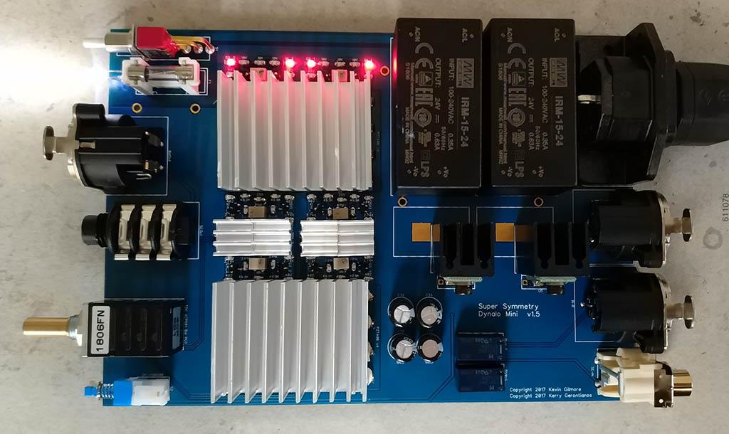
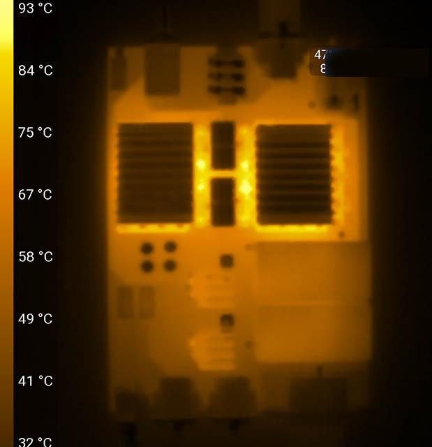
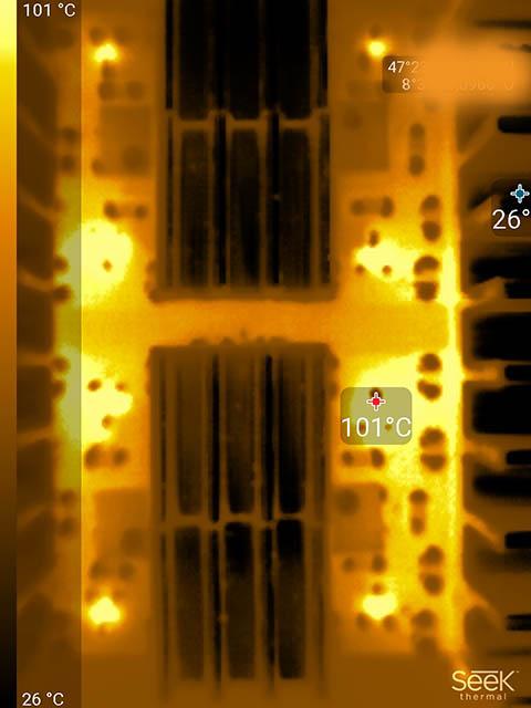
Another smd Dynalo is born, verry happy that i could manage that. First time hand soldering so much smd parts und my eyes getting older. Was not easy but worked out and the sound is great. Gets very hot with the 422 402 ohm, same heat as the one from pars. I use my seekpro form some thermal pictures after 45min, for me ok when i use it but wouldn't give it away with this heat. For the Heatsinks i used thermal adhesive, due the different ems from raw alluminium the thermal camera show the temp to low, they are hotter then the pcb but not over ca 80 c. Hottest parts are the small transistors. Tip to measure raw alluminium with a heat gun stick a black adhesive tape over it. Thanks for the group buy of the pcb, the group buy of the case and all the support i get from this great forum.

-
Package arrived today, thanks a lot for your work, very happy ?
-
paid, thanks for your work ?
-
Package arrived, was away some weeks, thanks ?
-
payment sent, thanks a lot for your work ?
-
paid, thanks
-
i had the same as you, couldn't get over 300mv, then i tried 620ohm - even lower bias. so i tried the other direction ;-). sip socket makes that a lot easier, i solderd them in after the desolder of the 500 ohm resistors.
-
i used some sip sockets for the 500 ohm resistors near the 10k pot, makes the change easy. the value of the 500 ohm resistor depends on the vf voltage of the leds you are using, i ended up with some 374 ohm resistors for 620 mv bias (due the relative small case).
-
paid, thanks
-
do you made a balanced ksa5 with two boards? some pictures would be nice :-)
-
go for the ksa5 with a golden reference power supply, not to tricky to build and no heat monster. read the two threads for the ksa5 and the grlv and match the parts for the amp (cheap transistor tester do the work quite well). if you want some action, some brrrzzzz and puff go for something high power, high heat, high voltage. i'm shure you would then increase your desolder skills, a good thing but advanced projects are often also a money pit :-(
-
Definitely interested.
-
RIP Johnny Hallyday
-
thanks kevin, learned something new :-)
-
hi jose i think if you want to adjuste the voltage via rv2/rv1 you don't need the resistors in r7/r8 , r9/r10. maybe someone can correct me if i'm wrong, i think either via r7/r8 , r9/r10 or via rv2/rv1, not both.
-
to shield the trafo enough in your build you need some metal that can shield magnetic fields quit good (mu-metal or grain oriented metal). i used also this transformator can (when the trafo is not so near sensitive transistors) but i would rate the magnetic shielding the badest. would rate: mu-metal 100% grain orientad metal 80-90% normal metal (this can) 30-40% due mu-metal is horrible expensive the best way is to go for the grain oriented metal option. i used this transformator can and grain oriented metal bands in one of my ksa5 builds (bad placed trafo in my first ksa5 (the red one)), looks nice and shield effect in combination is as good as mu-metal. so you can first test the noise with this can and later ad some grain oriented metal bands if needed. the noiseest part of the trafo is the side where the cables go in and out, place this part away from the transistors (in your build to the front side). also very effectiv is to turn the trafo up 90 degree (stand up), the magnetic field expands more like a frisbee (then a sphere) around the trafo. the first time putting a grain oriented metal band over the trafo and the hum goes away is magic :-).
-
good to hear that you amps is working again jose. i had also 1 noisy out of 6 that340 from mouser, would be nice to test some single jfets or have them as alternatives.
-
thats not all, you can choose every stone you want and bring them a sample. then they decide if the stone don't effect the sound quality. they made one he-1 out of jade for a chinese customer. so noble sirs and ladies, it's now time for some creativity and a short call to your banker. of course they are open for your ideas (other knobs?), the conversation i had with my conciergie was nice, friendly and sometimes out of this world ;-). they made a real special services arount the he-1, was a nice experience.
-
that's exact my feeling with the he-1. i had 2 1/2 h nice hours with the system but wasn't overly impressed, could get more time because no other appointments this afternoon but was fine for me. was a nice afternoon because the system was 1 week in zurich, 15 minutes walk from home at a store i know the owner since 20 years, could do with the system what i want. sounded nice, detailed and smooth with a little tubby touch. i would buy the headphone allone asap but due the closed system it's nothing for me. and i don't like the idea of moving parts (rising tubes), looks nice but it's also durable?... as whole system i like my sr-009 or sr-007 tuned via a avalon ad2055 and out of my bhse better. it's a nice "to-go" system for audiophile high-net-worth individuals. service around this product is top, nice responsive concierge service. i uploaded the brochure i get from them up to dropbox, have fun with it: https://www.dropbox.com/s/74tewziqkroheao/HE1_Imagebroschüre_570759_0716_Customization_EN (003).pdf?dl=0
-
hi jose do you have onboard heatsinks? i think the right bias for the onboard heatsink is around 0.375v but always only as much the amp get in a stable state (heatsink rise max 25 c over ambient or at cold places 30 c after 1 1/2 - 2 hours). if you only test the amp for 1/2 hour the amp can run away later and as the temps rise the bias get faster higher to a point the parts can fail/get damage. its a even bigger problem if the transistors are not well matched, the unbalance get fast out of a stable state, the fun and tricky part of a lot of nelson pass amp designs. i had some similar effects with a amp, some mosfet get to much current/heat but not failed completely, they made some strange chirr crackling noises (allways, sometime louder). was tricky because they measured fine whitout high current. what kind of noise do you hear? more static noise (as pink noise), hum or chirr/crackling noises? i think "fried" sounds like damaged but operational parts. static noise is often because high gain and not so good matched parts. hum noise often fron grounding (wiring) problems (both channels same hum) or magnetic inducted noise from the transformator (the channel near the trafos hums louder then the other or only one channel has hum). hope helps a bit.
-
yes the orientation is fine of the opa445 and i also tested 2 seperate opa445 i had at hand. what puzzels me is that the vf of the one led drops 0.1v when the opa is in, is this a part of the servo function? after my first troubels i changed both leds to the LTL-307ELC, the vf is a tad lower then the clear led i used but easy to correct to the target bias changeing the 500 ohm resistor (now use a 357 ohm for bias around .575v). both led types dim with the opa in (on both boards). i also changed the that340 to 2 others, the result is the same with the servos. but im happy, the amps is running at the moment an with the lid closed the offset on both channels are stable at under 2mv (with opa the offset multipies by factor 20). god that i machted 80 mje's and 100 pzta's, the amps sounds perfect and is noise free. maybe someone with the same board in the future has a better understanding than i have .
-
thanks will do that next weekend. sometimes its good to run in some troubels, then the learning curve is the highest ?. great to have this forum and the help of you and the members.
-
thanks a lot mr gilmore, you allready answered my next question. whitout opa (i used the opa445) i have a stable offset +- 3mv around zero after a half hour, at start 20mv fast dropping the first minute to under 10mv, that's fine for me. so i will use it whitout the opa. thanks a lot for you help - it's a sexy design the dynahi. strange is that both boards have the same problem with the opa in - the offset hovers slowly to over 0.3v around zero in both direction, a bit scary with this amp. out of interest, is it possible that the servos correct the offset to much when the parts are very well matched and the offset is stable going down to near zero? other class a power amps i made have a more agil bias swing then the dynahi.
-
thanks mr gilmore, great tip. betweeen pin 4/7 it's 60 volt isn't that to much for the opa (should be 15v when i watch the diagrams), between 2/3 ~20 volt. the older version had some 7915/7815 are they obsolet?
-
my dynahi has a problem, i tested the offset after some hours. i can bring down the offset to around +- 2 mv, i matched all transistors. the vf of the two leds whitout the opa is 1.75v. the problem is now when i put in the opa445 in the led on the side of the opa dims and the vf drops to 1.64v, resulting in a offset drift +-80 mv . this is the amp https://www.head-fi.org/gallery/photo/kevin-gilmore-dynahi.1871812/?regular=1 . would be great if anyone could point me to some additional measurements of have tips to solve this. took great care with soldering and measured any resistors twice, don't think it's a bad solderding or missplaced resistor. any feedback helps :-)