kevin gilmore
-
Posts
7,197 -
Joined
-
Last visited
-
Days Won
21
Content Type
Profiles
Forums
Events
Everything posted by kevin gilmore
-
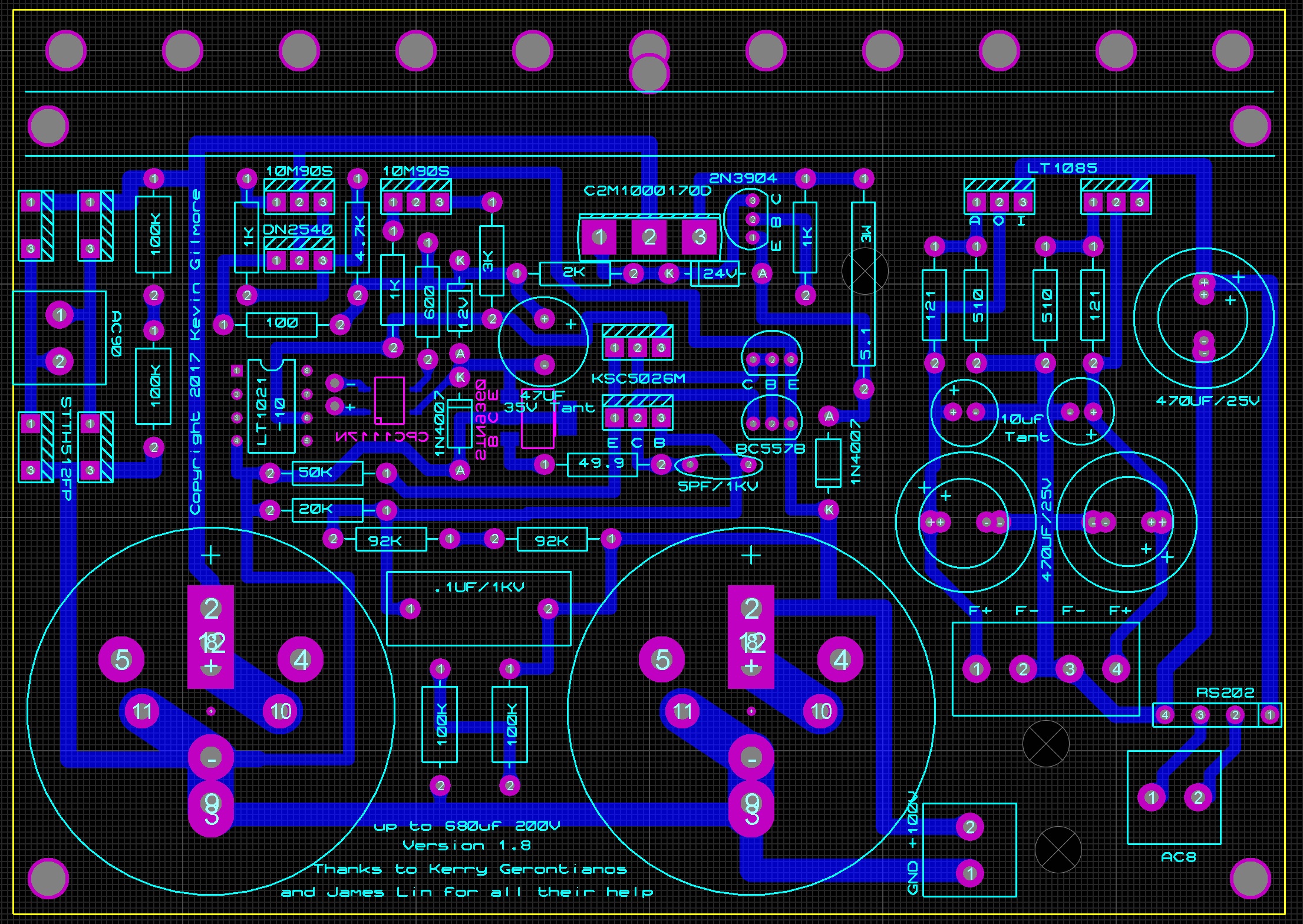
standalone grhv for 100v and regulated filaments

-
12 inch and 10 inch drivers? similar to what Wilson does?
-
they are definitely elna caps, and look to be the exact same physical size as in the t1, so 100uf
-
I did notice they were 400v caps, but don't remember the value. birgir will know in about a week. The 100v supply wastes about 8 watts. so that really needs to be a separate winding off the transformer.
-
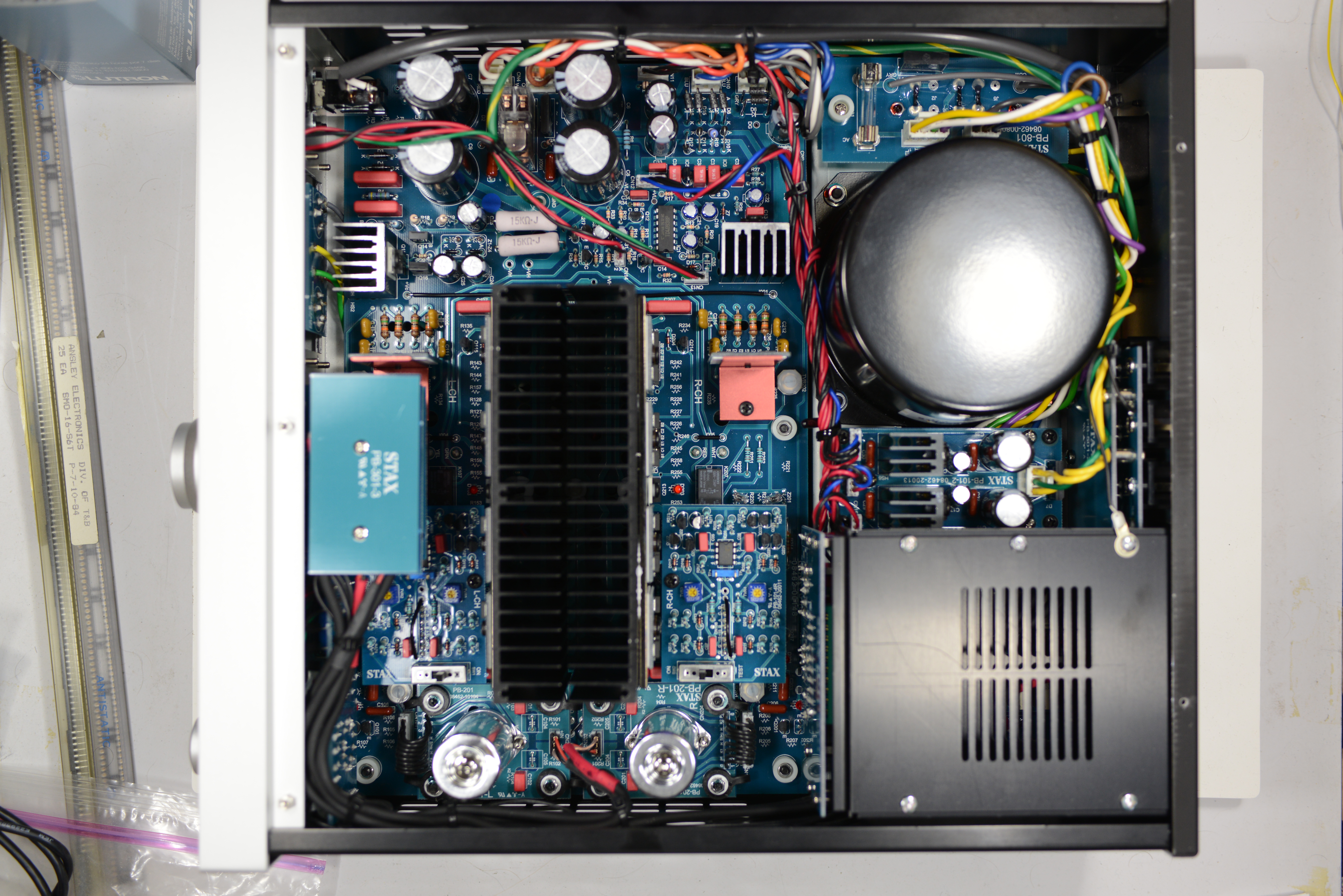
its clear that more than one person spent a bunch of time on this. 14 different circuit boards, 2 piece custom extrusion for the front, all chassis pieces painted aluminum etc. So a lot of money spent. Too bad the design is 20+ years old. Too bad they refuse to do a regulated power supply. Too bad they won't make it big enough to do 20ma output stage current.
-
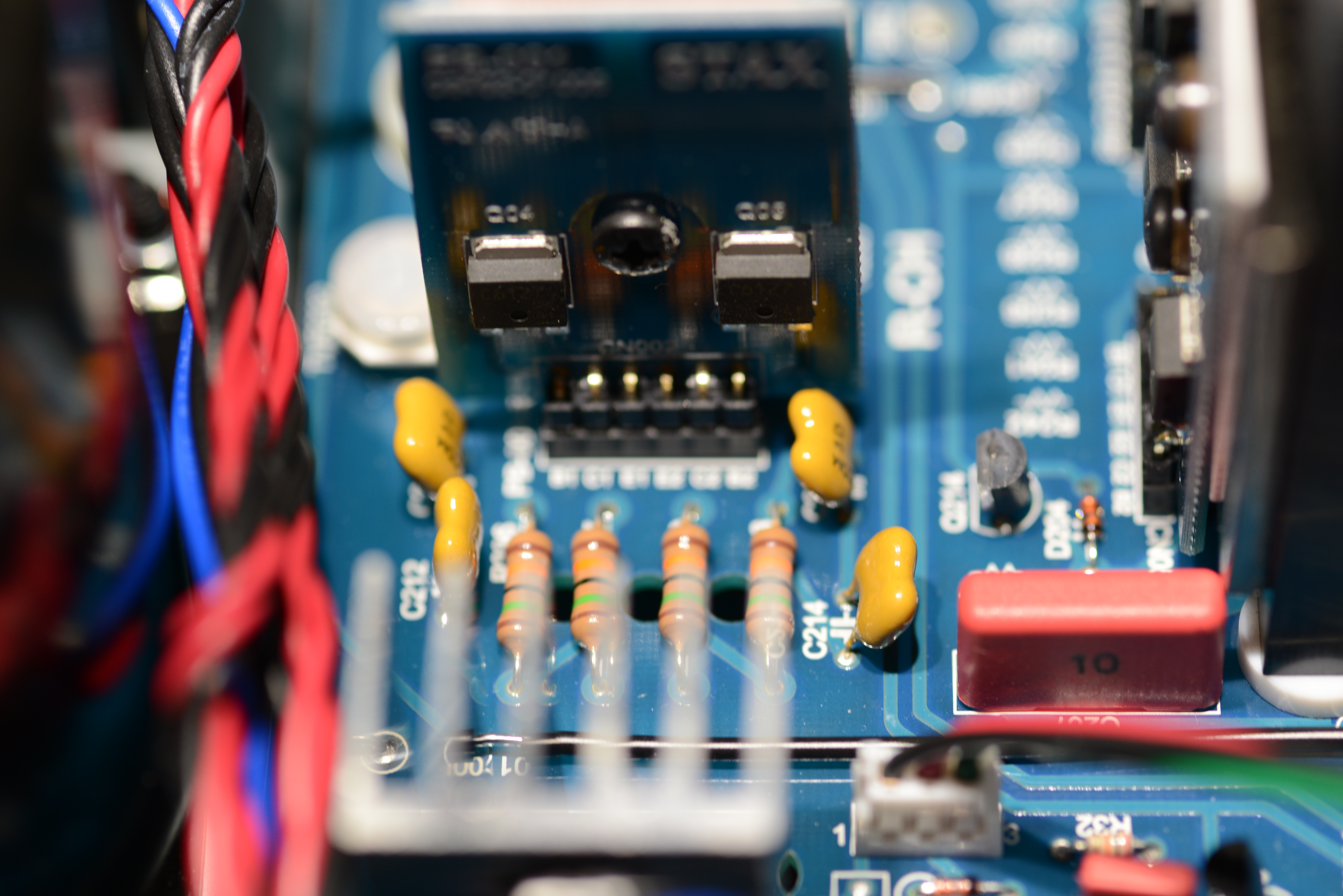
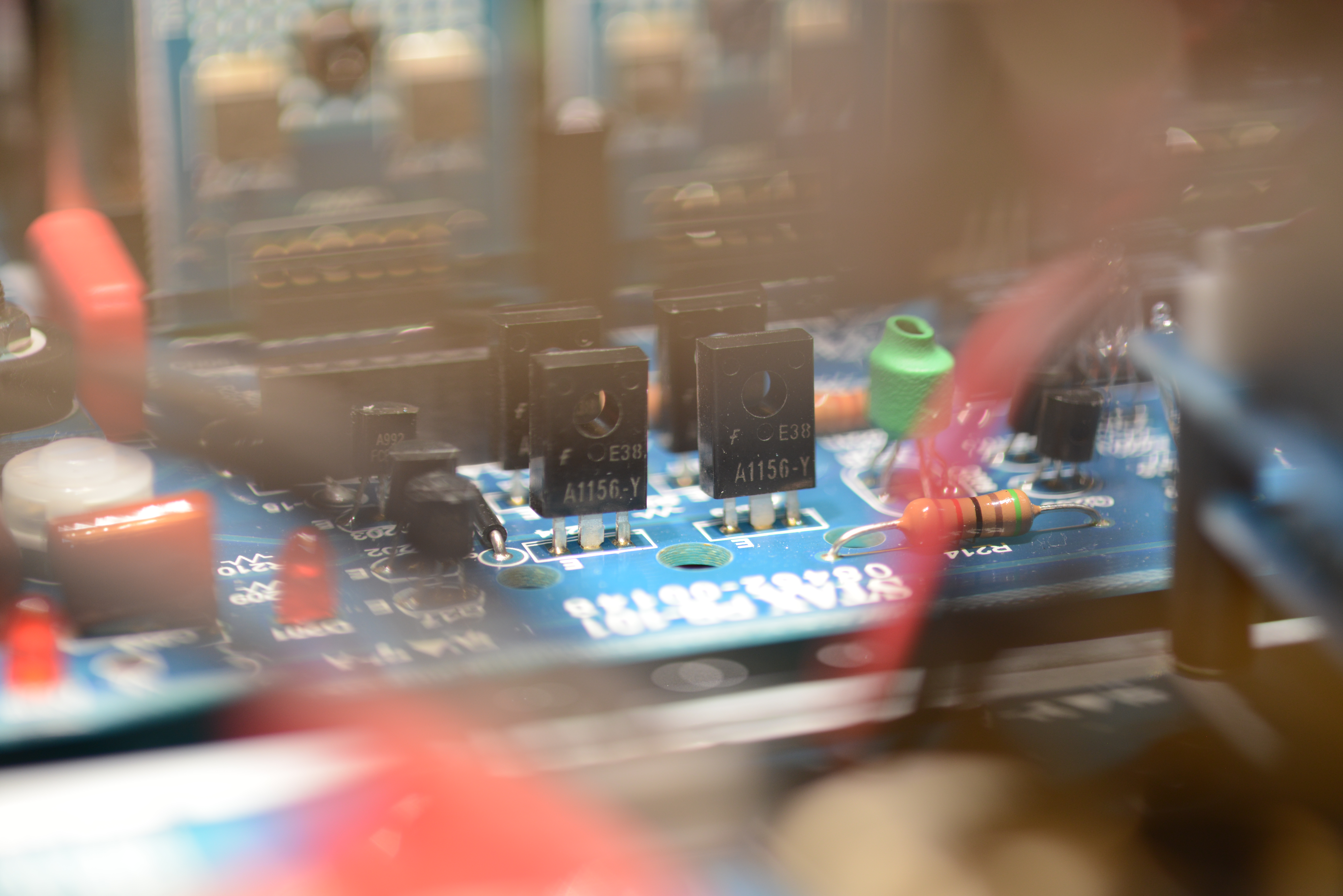
q19 and q21 are in all stax amps. limits the voltage of that particular section, they never trigger, and I eliminated them a long time ago. q27 and q30 are used as temperature matched diodes. same as Q8 which is mounted on the heatsink the 300k resistors result in a voltage gain of 1k (actually a bit more) when combined with r38,r39. carbon does the same thing with lower resistances they use stacked ksa1156, a pair of 400v parts. I use the stn9360 which is a single 600v part. there is no reason to do this in solid state front end amp because the 100v is 15v main power supplys are not regulated. and the servo jumps all over the place when the air conditioning kicks in.
-
simplified schematic just updated, I got the current sources flipped. when put in the test position, it puts fixed resistors to the plates of the tubes to -15 so then you adjust the main offset and differential. then move back to the on position and further adjust the servo pots. when working right, keeps the outputs to less than 100mv. but range is very tight.
-
I was listening to it while taking pictures... multitasking absolutely, don't want any metal nuts floating around in bad places 2 of the screws that hold the bottom plate on have very long screws and nuts, both were loose, and one is almost impossible to get to without taking off the front panel.
-
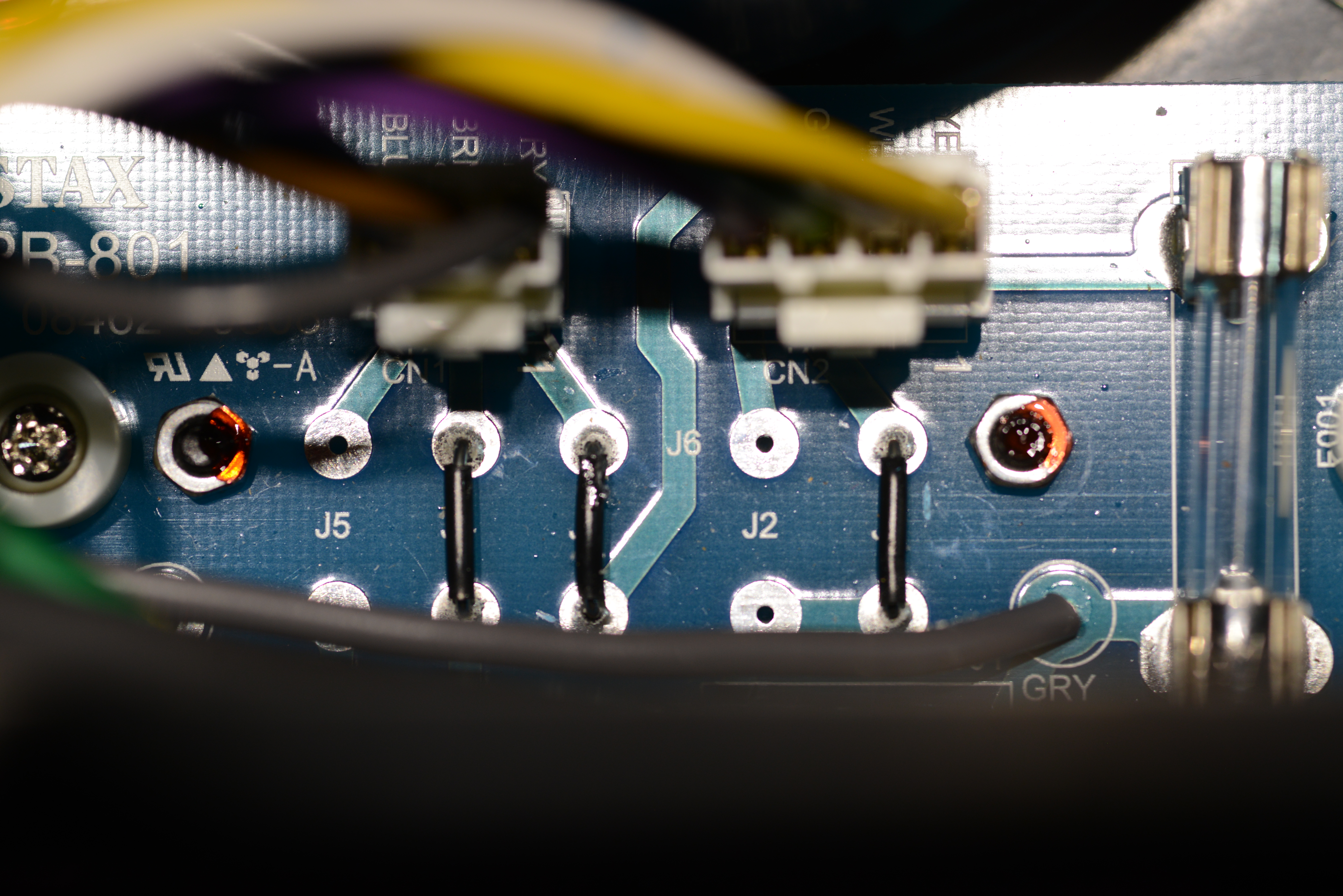
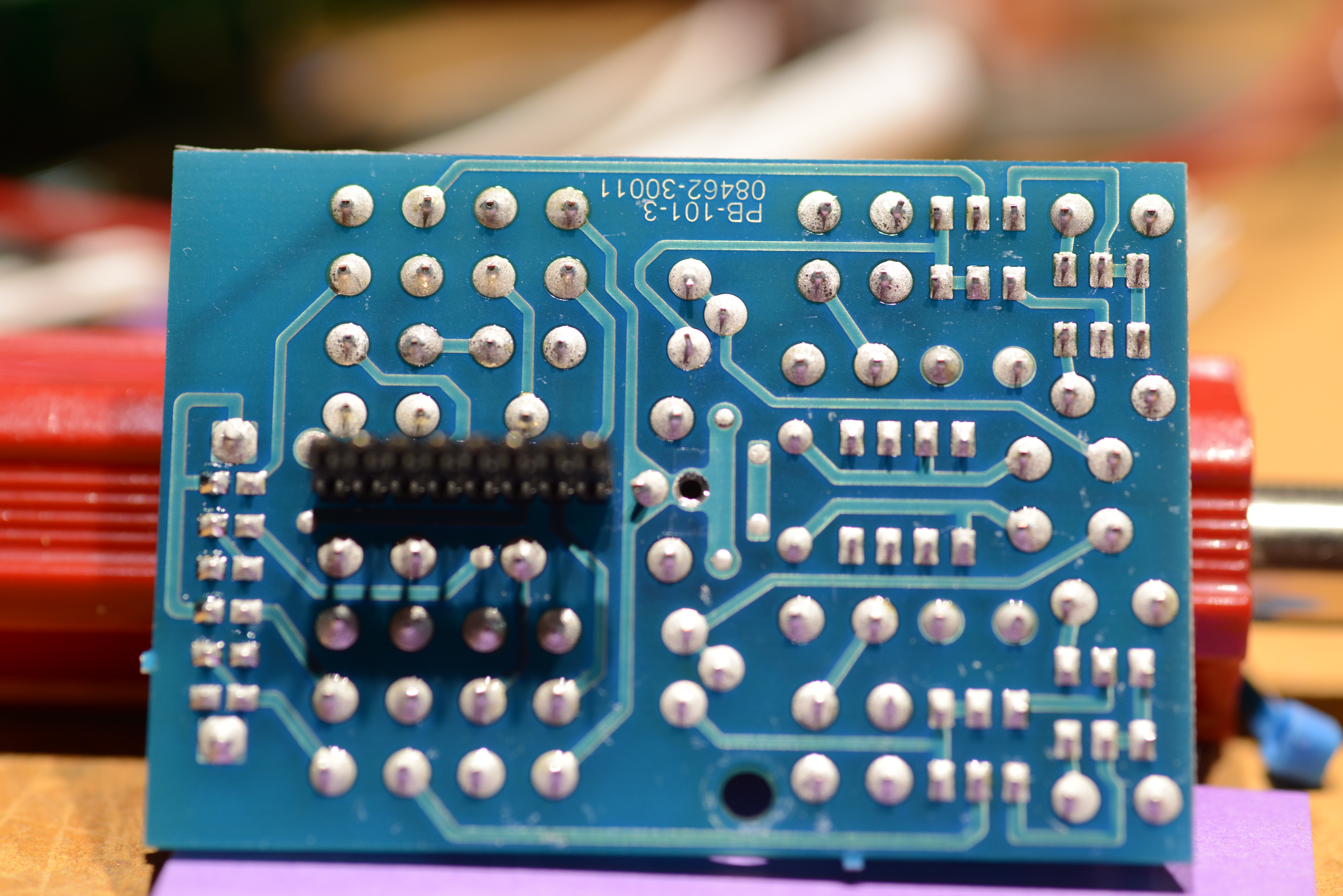
power jumper block cleaned of all the epoxy j1,j3,j4 for 100v remove all others j2 j3 j5 for 120v remove all others j5,j6 for 240v remove all others and servo board pictures, unnecessarily complex tube rollers are going to have a lot of trouble with this, the servo has a pretty limited range, and the Russian similar's definitely will not work
-
here you go, a whole bunch of resistors are the wrong values, when I have time Power supplies are 350v t8000schem.PDF
-
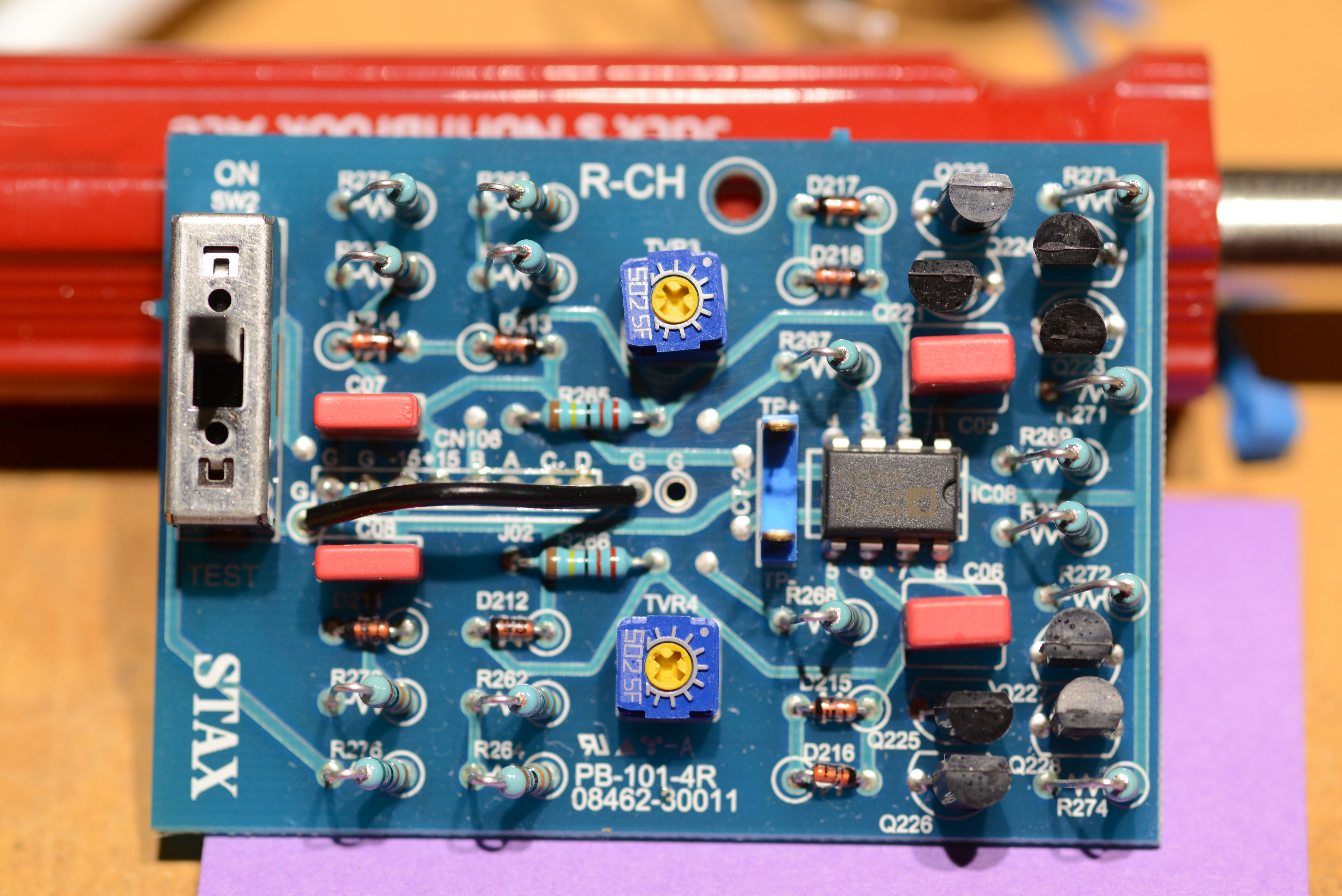
next to the transformer is 7815,7915 which makes +/-15 to the slot and also the servo board filaments are DC HV is unregulated Cap,100 ohm resistor,Cap servo pretty much identical to the T2 servo the 15k resistors are something else
-
I have your birthday present
-
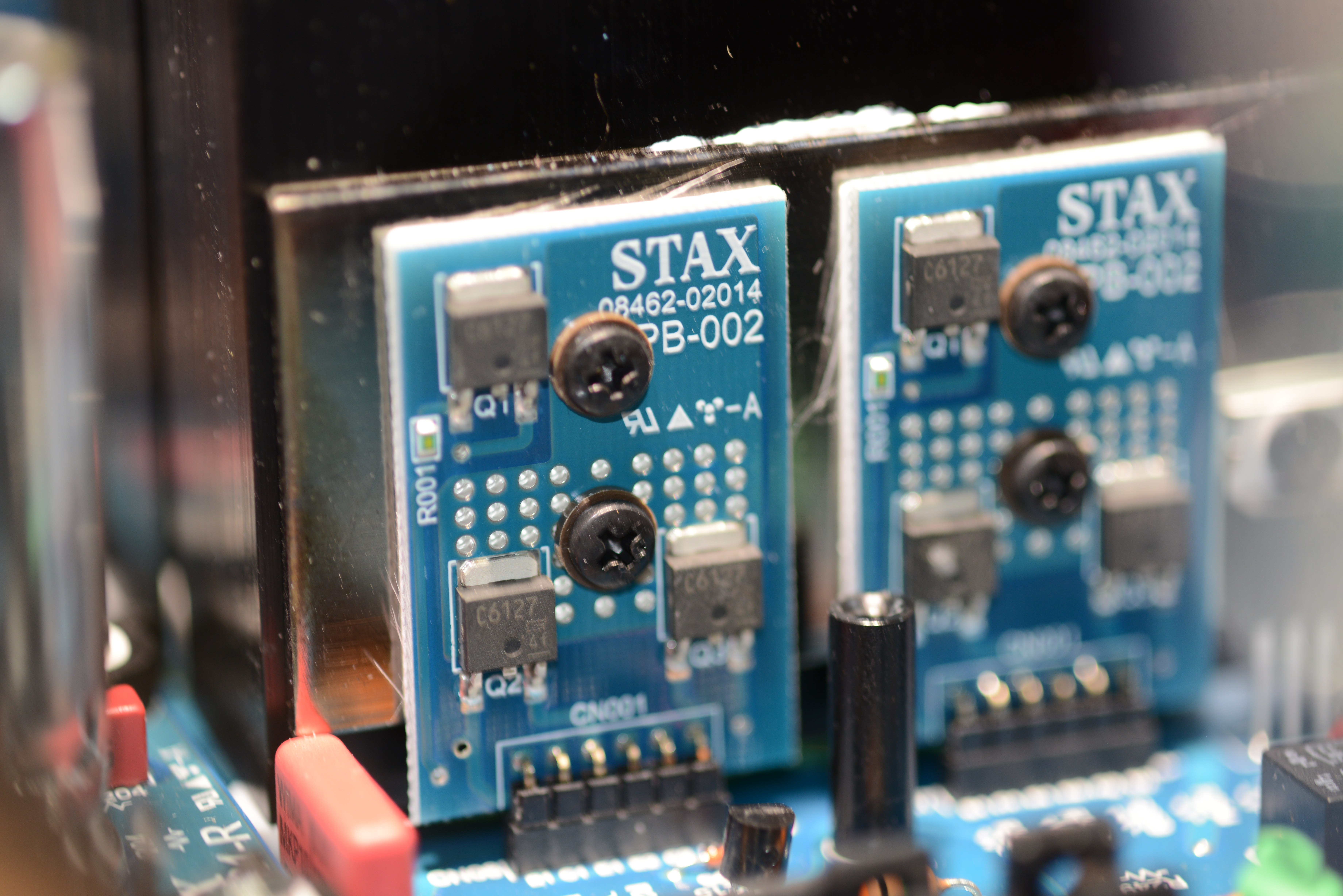
2sc6127 for the outputs and the voltage gain stage, resistors, for pull up on the voltage gain stage, darlington output need better picture of servo, so that one later, stacked ksa1156 for the tube drive, the rest of it is a modern 717 with available parts. wiring, 100v J1,J3,J4 120v J2,J3,J5
-
its birgir's birthday today, the big 35! so... special security screws on the top, 6 sided ultra miniature metric spline, apple tools work power conversion relatively easy once you get rid of the goop
-
suggest you build the kgsshv-carbon first. do it as 2 chassis leave extra room in the power supply for a filament transformer and extra pins in the connector then you can build the GG as a second amplifier and use the existing power supply then even later you can upgrade the GG to DHT tubes simple
-
definitely not. srm727 output stage running at 5 to 6 ma, and tube front end. but we will have schematics soon.
-
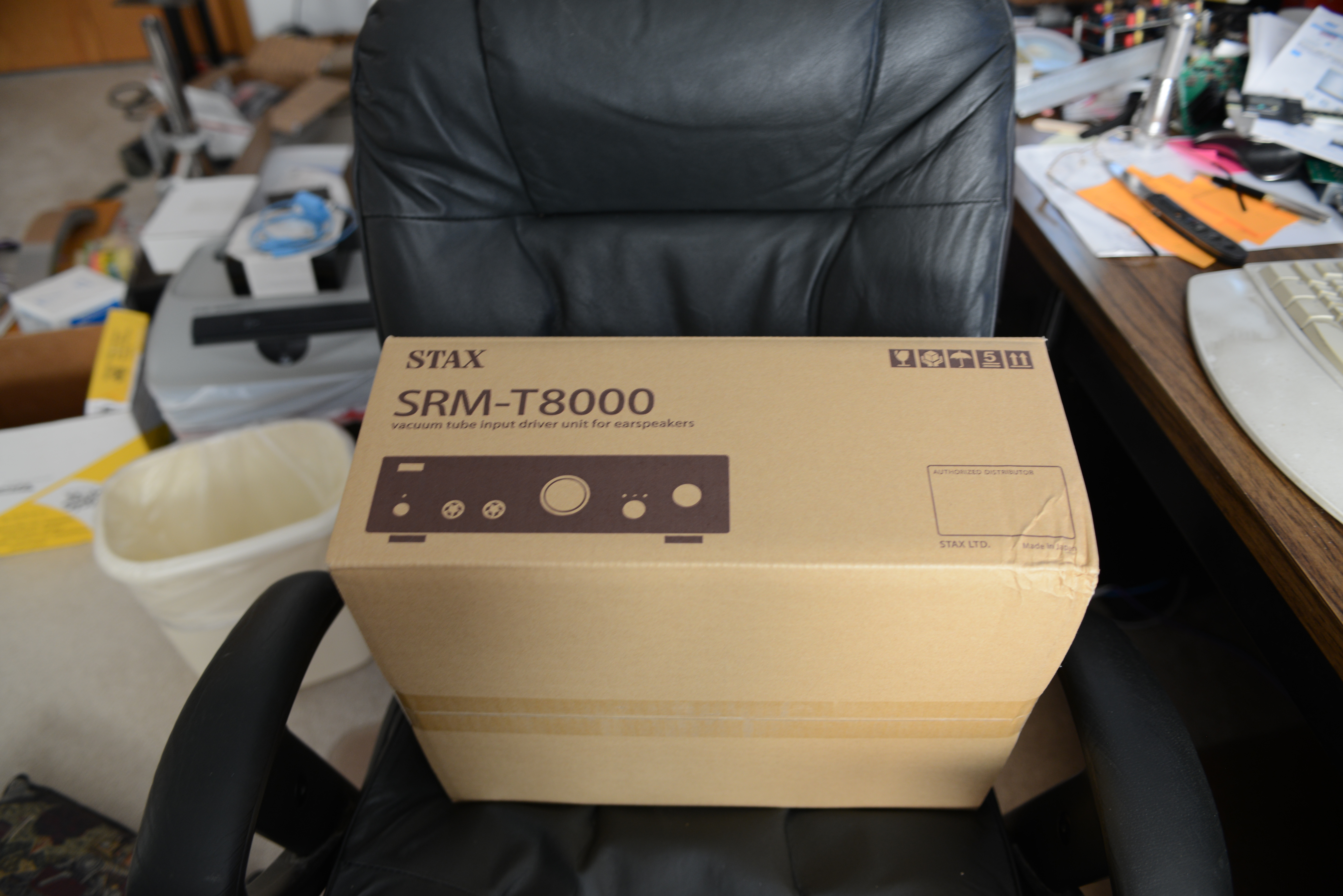
in other news I have a tracking number now, so the t8000 is on its way
-
work in progress hangs off the side with thin angle bracket, no drilling of holes
-
5V thru a resistor or 12V driving the cpc1117N opto coupler so after 30 seconds you apply a voltage, delay timer 555 or similar, same as T2
-
the resistor marked open, put 100k there and see if it makes any difference. but with all tube amps, you really need a delay on the high voltage, most of the current high voltage boards have a switch, but you need a delay board to drive them.
-
no feedback and a voltage gain between 500 and 1000 yep that is going to work, for at least 15 minutes till the tubes drift.
-
a bit more current to bring the plate voltage down a bit
-
noise level due to input tubes?
-
That resistor was for lowering the gain when using the original opamp and a pair of diodes. will add a jumper once the board is verified
-
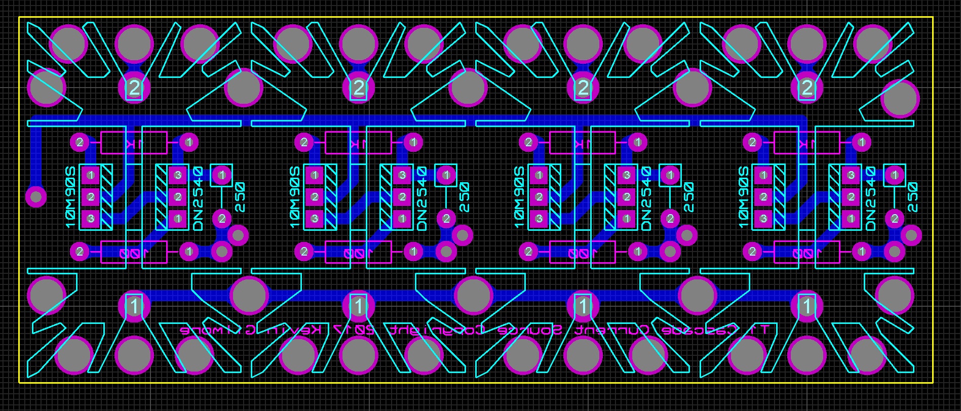
happy it works. now for a version with tubes as the constant current sources And a cherub has just informed me a t8000 is headed my way I like retirement. going to a hamfest tomorrow to see what I can find to update some of my very antique test gear