kevin gilmore
-
Posts
7,204 -
Joined
-
Last visited
-
Days Won
21
Content Type
Profiles
Forums
Events
Everything posted by kevin gilmore
-
the coupler needs to be .25 inch on one side and 8mm on the other side. you will have to take a standard coupler and drill out one side.
-

Wells Audio amps....any experience?
kevin gilmore replied to HemiSam's topic in Headphone Amplification
output inductors means circuit is unstable. and the bybee stuff means the entire thing is a piece of crap. -
and now for something completely different part 3
kevin gilmore replied to kevin gilmore's topic in Do It Yourself
well it only really makes a difference if you have a dac with significant amounts of dc offset. otherwise who cares. -
and now for something completely different part 3
kevin gilmore replied to kevin gilmore's topic in Do It Yourself
that is a good question. i'm not really sure of the answer, why not build both and let us know if it sounds any different. however using the input board gives much more common mode rejection. At least 10db, probably closer to 15 -
and now for something completely different part 3
kevin gilmore replied to kevin gilmore's topic in Do It Yourself
depends on how much heatsink you have. 150mv is a good starting point -
and now for something completely different part 3
kevin gilmore replied to kevin gilmore's topic in Do It Yourself
I would go with the new input board above, and then 2 x cfa2 output boards per channel. -
With a sine wave generator driving the amp, would make a perfect tig welder. Change the frequency to control bead size.
-
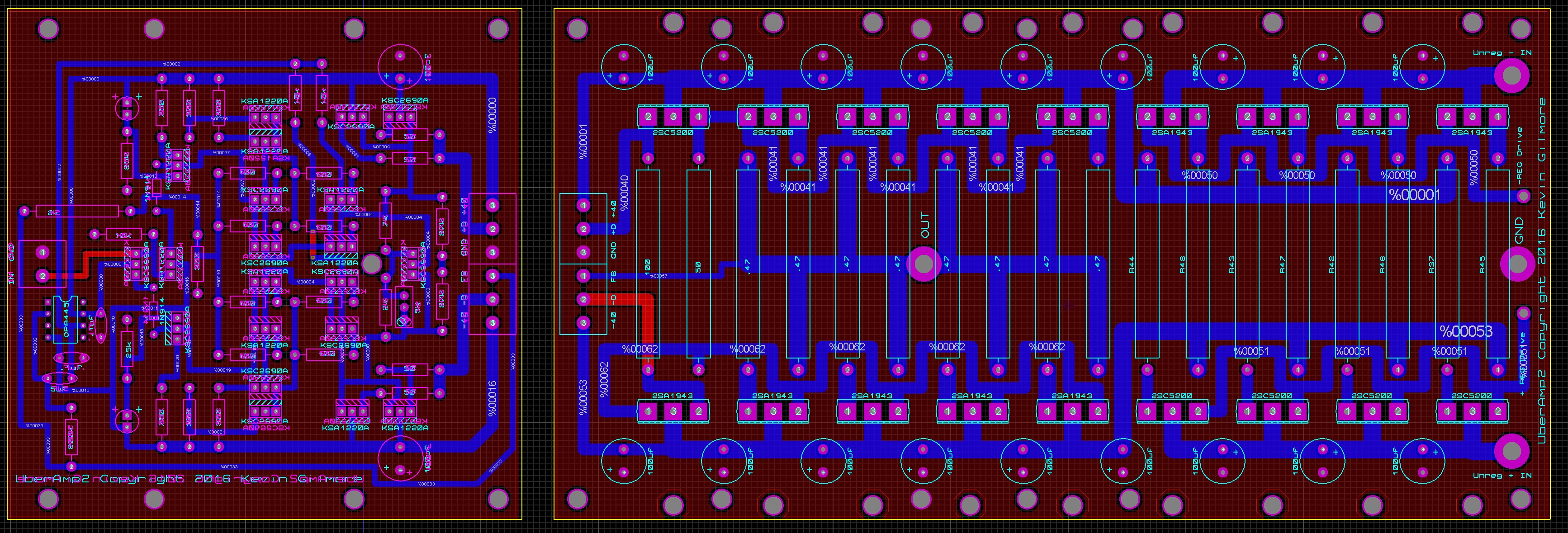
uberamp will drive anything i can think of. no protection circuits of any kind, and just about unlimited current capability.
-
the carbon for dht definitely works as does the kgbh-bipolar-dht the carbon for 6ca7 evidently does not work, congo5 has some spare boards contact him for a pair, might be an assembly error (doubtful) or some bad parts the shrunk boards fit a 100mm heatsink vertically.
-
and now for something completely different part 3
kevin gilmore replied to kevin gilmore's topic in Do It Yourself
2 input boards, 4 driver boards, 4 output boards one grlv @ 30v or 2 if you really want to do dual mono one grlv @ 40v or 2 if you really want to do dual mono one or 2 bigass transformers, stack of unregulated caps and 25 amp diode bridges mounted to the bottom. current version looks a bit different. for the driver board, can stuff parts either top or bottom (other than opamp) and all the holes line up to stack all 3 boards on top of each other.
-
the opto version only works in one direction, so the output needs to be at least +10 before turning on the servo
-
yes you definitely need the opamp, otherwise the opto has no drive.
-
goldenreference low voltage power supply
kevin gilmore replied to kevin gilmore's topic in Do It Yourself
use 2 and make sure the pass transistors have enough heatsink, as in bolted to the main heatsinks -
the professional... (picture 9) http://www.head-fi.org/t/798779/sennheiser-he-60-baby-orpheus-w-hev-70-amp-original-box-immaculate the amateur seriously, ray has turned into a real sleezeball...
-
don't let any of the idiots over there know about this, the first thing that will happen is that someone will plug the tubes into a bhse directly and destroy $2k in tubes and probably trash the rest of the thing. these dht's have virtually identical curves to 6ca7 in triode mode.
-
i have over 200 op27 in stock. where i got them, no clue. but better than paying for them. finally had to buy opa445 from mouser as i ran out. one chip dead out of the package. have not seen that in a very long time.
-
you know that its possible that the hifiman amp has output transformers in which case the 300b would actually work as push pull. If so, what is that massive heat sink in the middle for. Still completely stupidass.
-
SE to balanced is what you probably mean, and you can do that. you can also do SE output, but then why?
-
Sure. Lower noise
-
I use 10k pots for everything. makes it simpler
-
http://gilmore.chem.northwestern.edu/currentamps.jpg
-
the stax mafia are definitely planning on a multibit dac. Problem is finding switches good enough (and fast enough) to do 24 bits, 1/2 lsb
-
http://gilmore.chem.northwestern.edu/g9f21766.jpg
-
https://en.wikipedia.org/wiki/Joe_Alaskey
-
Expensive and/or raved-about headphones that actually suck!
kevin gilmore replied to Bjorn's topic in Headphones
I got my hands on the old Tektronix all tube curve tracer, the high voltage version goes to 1700 volts. I tested about 50 6ca7 tubes, no 2 indentical. not even close. did the same thing with c2m1000, and to the resolution of the screen, fairly easy to get bunches of matched quads but there is still some variation.