


JoaMat
High Rollers
-
Joined
-
Last visited
Everything posted by JoaMat
-
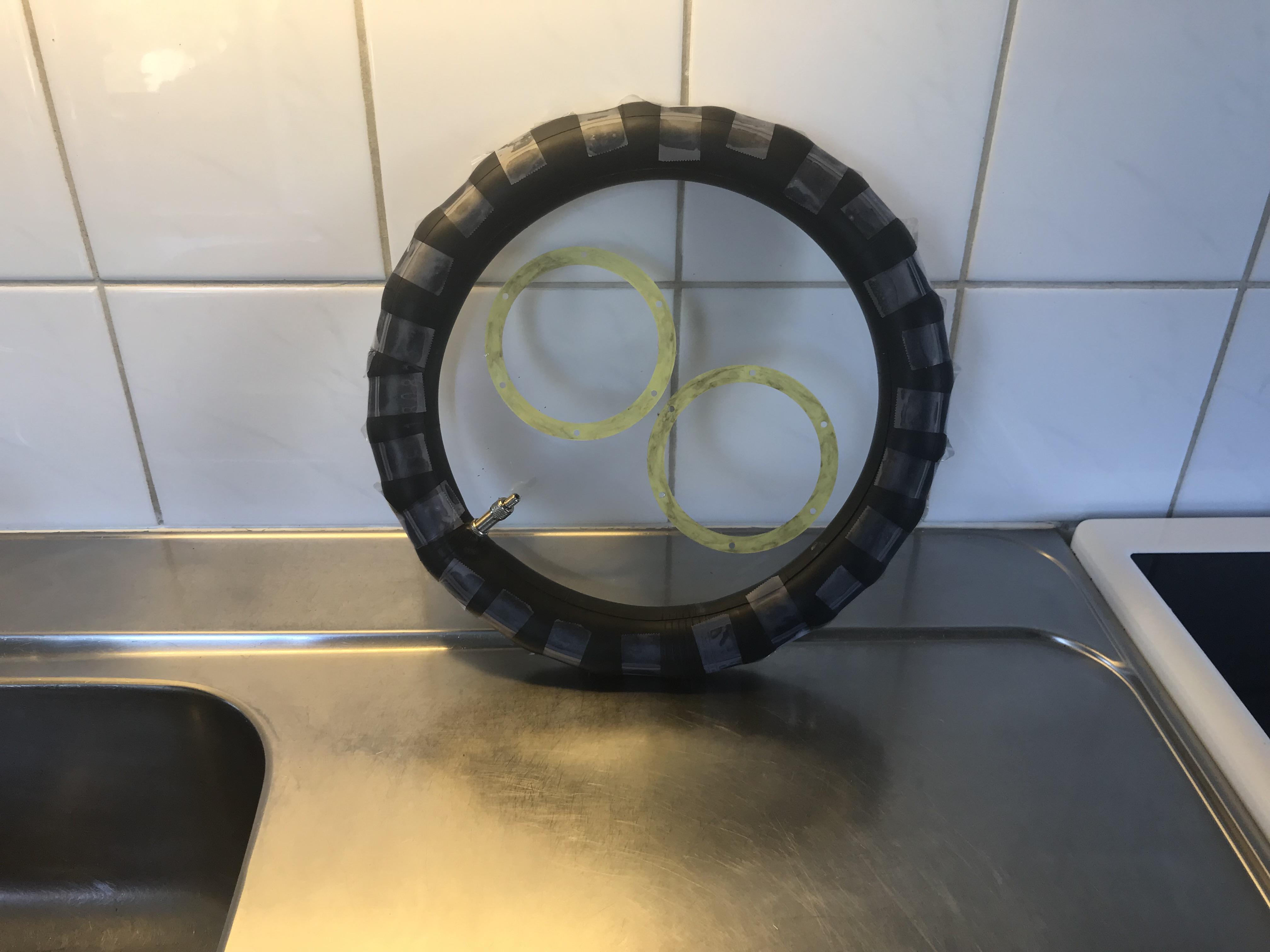
Happy Birthday, Kerry!Thanks for feedback. Those diaphragms in the picture were much more stretched then the previous I‘ve made. Seems I’ve to keep on trying to make diaphragms with the right tension.I’ve retested and I got about the same results. Also tested a pair of SR-007 mk2 and then I got graphs more like your Orpheus Clone and 007mk1. I’m very satisfied with the bass, well not as good as 009S but good for my DIY headphone. I’ve tried different diaphragms and some of them are terrible, but I actually manage to do some better. Another thing is that my home made phones are not as sensitive as Stax and the diaphragms need time to charge. They start soft and after half an hour or so the sound reach it’s max. Here is how I stretch the Mylar film. 12 inch inner tube and Scotch Magic tape.
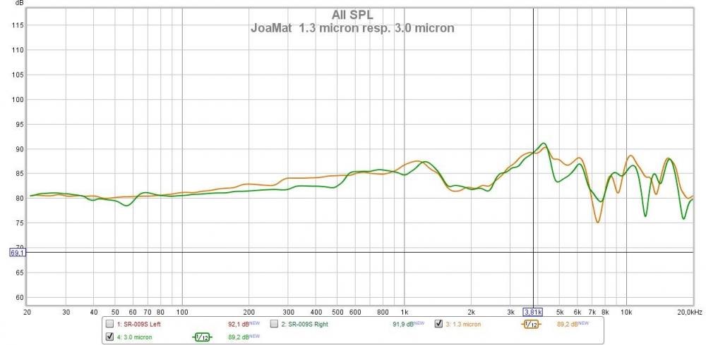
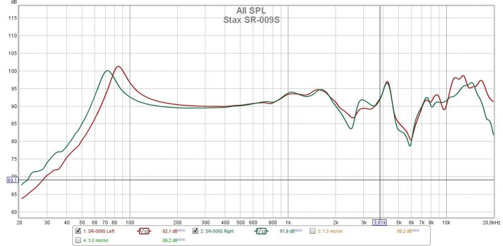
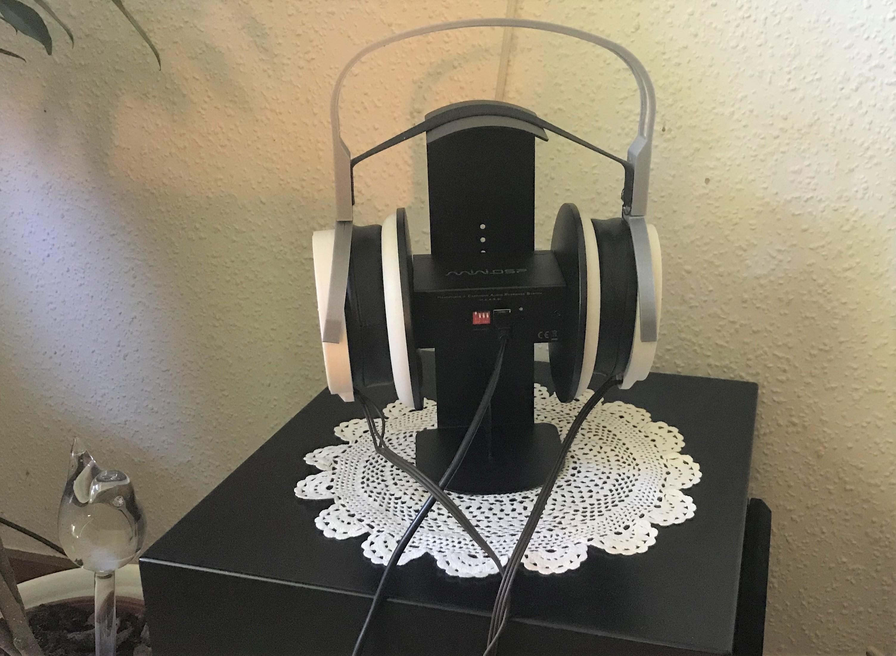
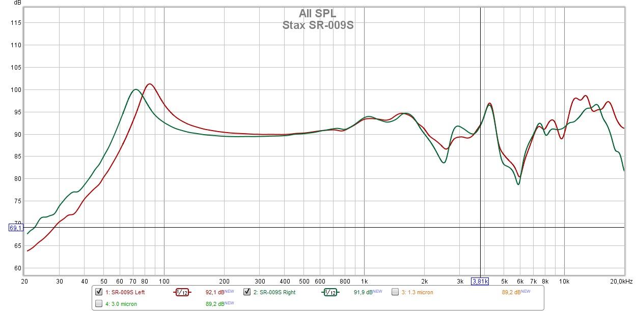
 Wow magnificent! Nascent Audio?Today a miniDSP EAR arrived. Have made some measurements and I got the below graphs. I just followed the manual but I'm not sure how to interpret the outcome…
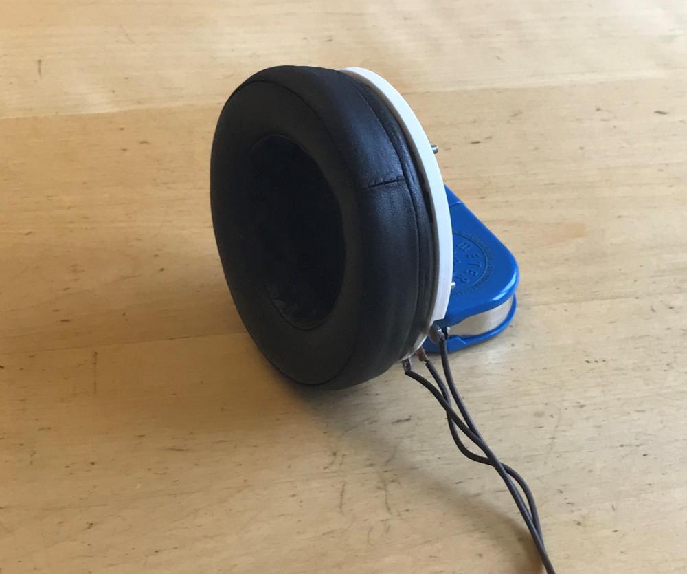
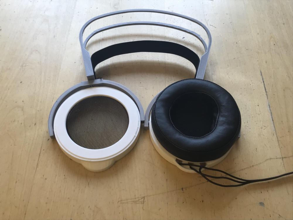
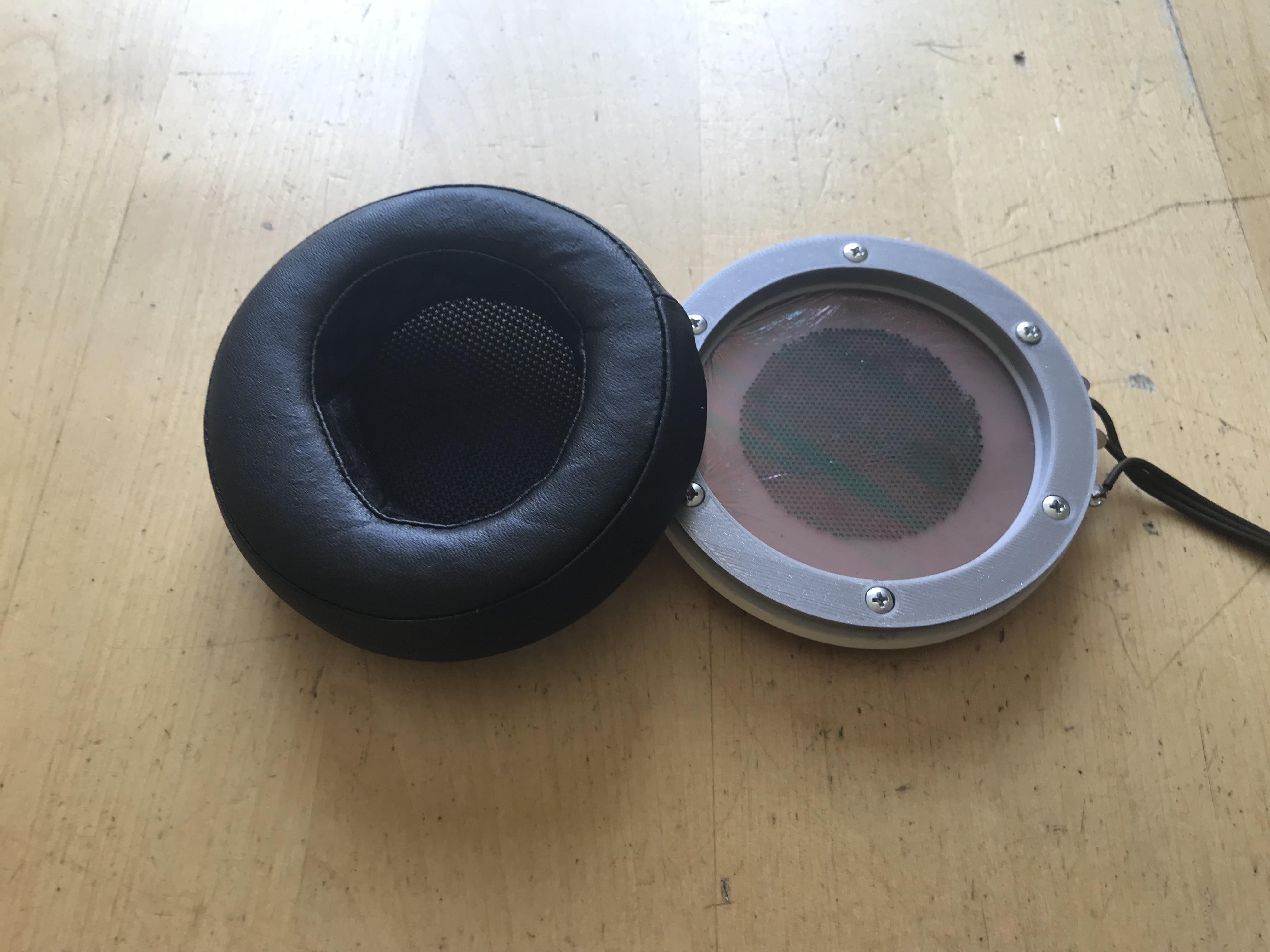
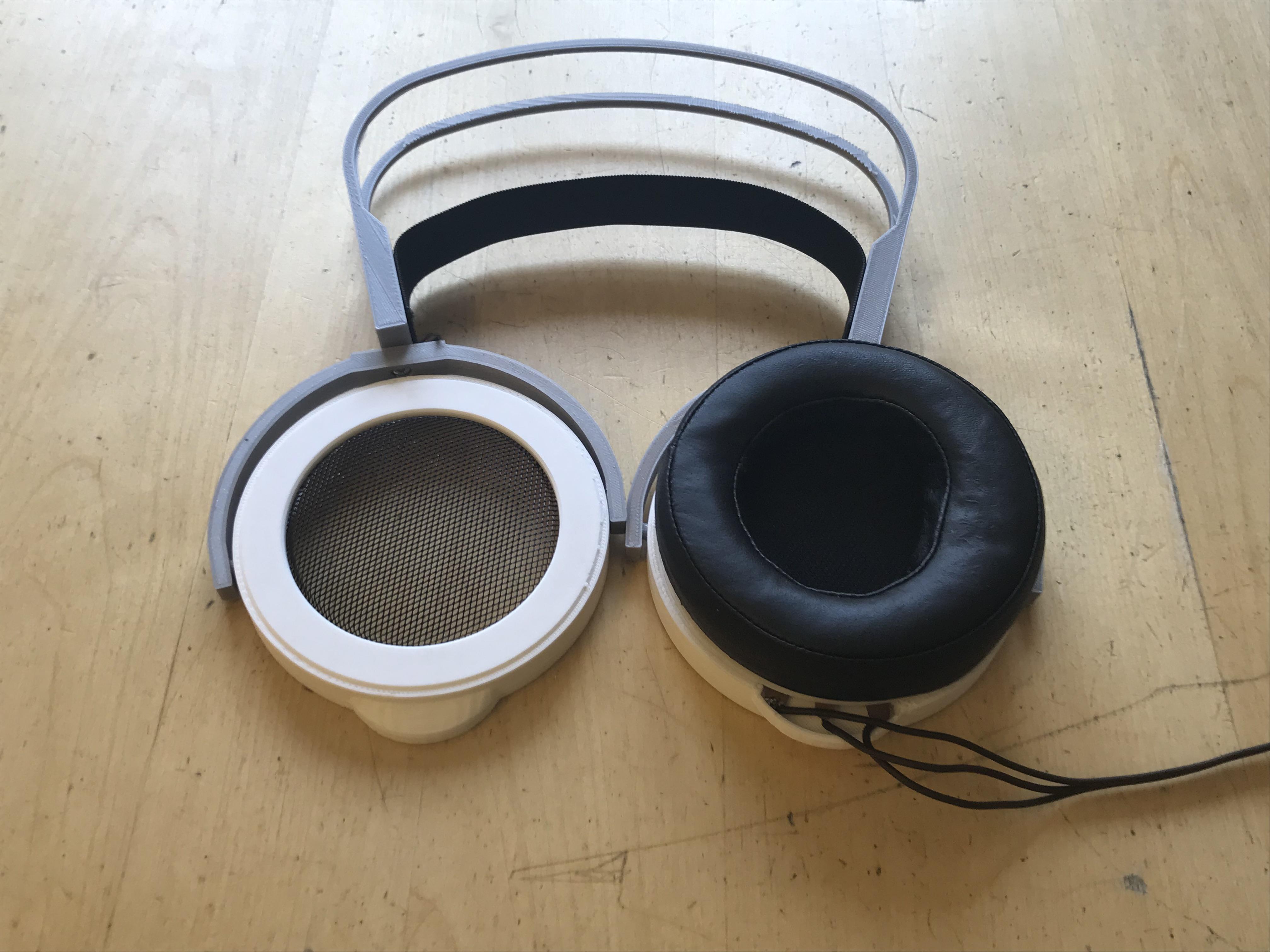
 3D printed ”pad holder” today. The grey thing attached to the driver unit with six screws. SR-007 ear pad in place. Then take the package and push it into the frame – done. Found a piece of aluminum net and with some black paint it will serve as grill. Exposed cable connections. Have to fix that some time.
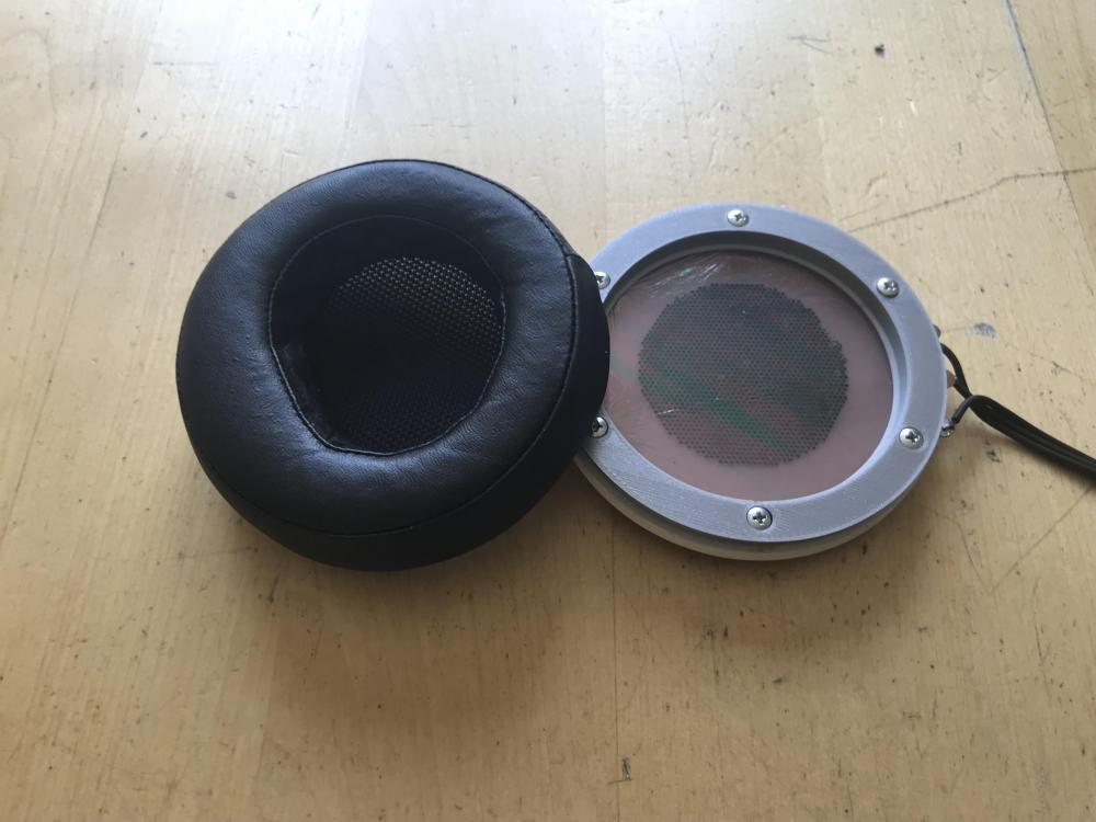
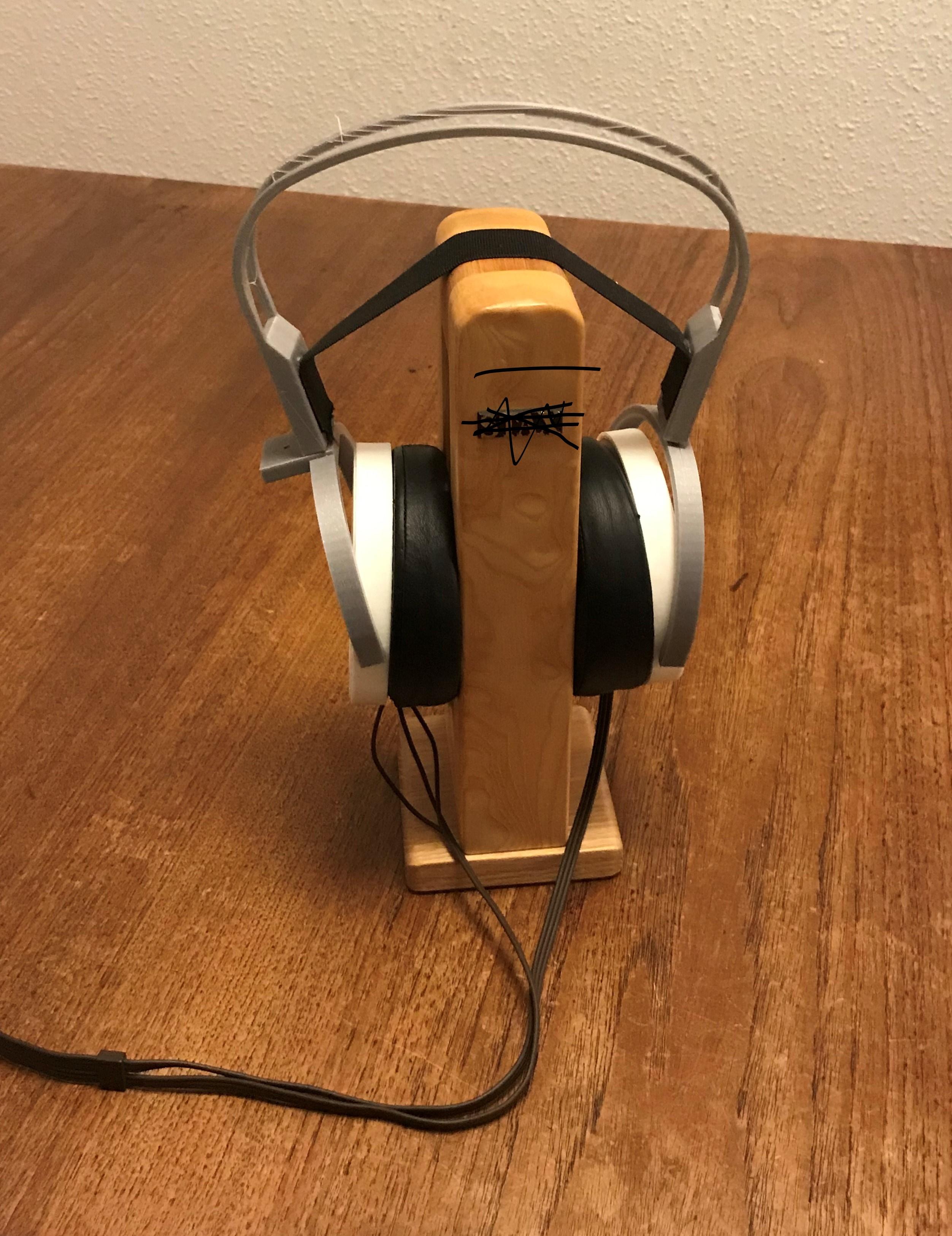
 Then I can sell my Stax phones. Considering the price level for used stuff I might capitalize them and buy myself a Mercedes Benz.Thank you. Yes, they are 3D printed. I’m using PLA filament but the intention is to use PETG or Carbon. For now I make a lot of prints. I have to test and then make changes and test again - a very slow process. I made a solid headband looking about the same as the one you see on the picture and it was very stiff - practically useless. So I removed 80 % of material and then it became a lot better. Sonically my Stax headphones are better but my home made one is much more fun to listen to.One side is with the “old” big holes stators and the other side has stators with small holes. I do feel the one with new stators ( small holes) is slightly less brighter. The phones have no dust covers and I hold the phones with my hands against my ears. As for diaphragms they are as they happened to be. I have no control over tension nor coating, so probably lots of factors affecting the sound. Today I’ve been struggling with Sketchup and 3D printing. For me it’s a slow progress.
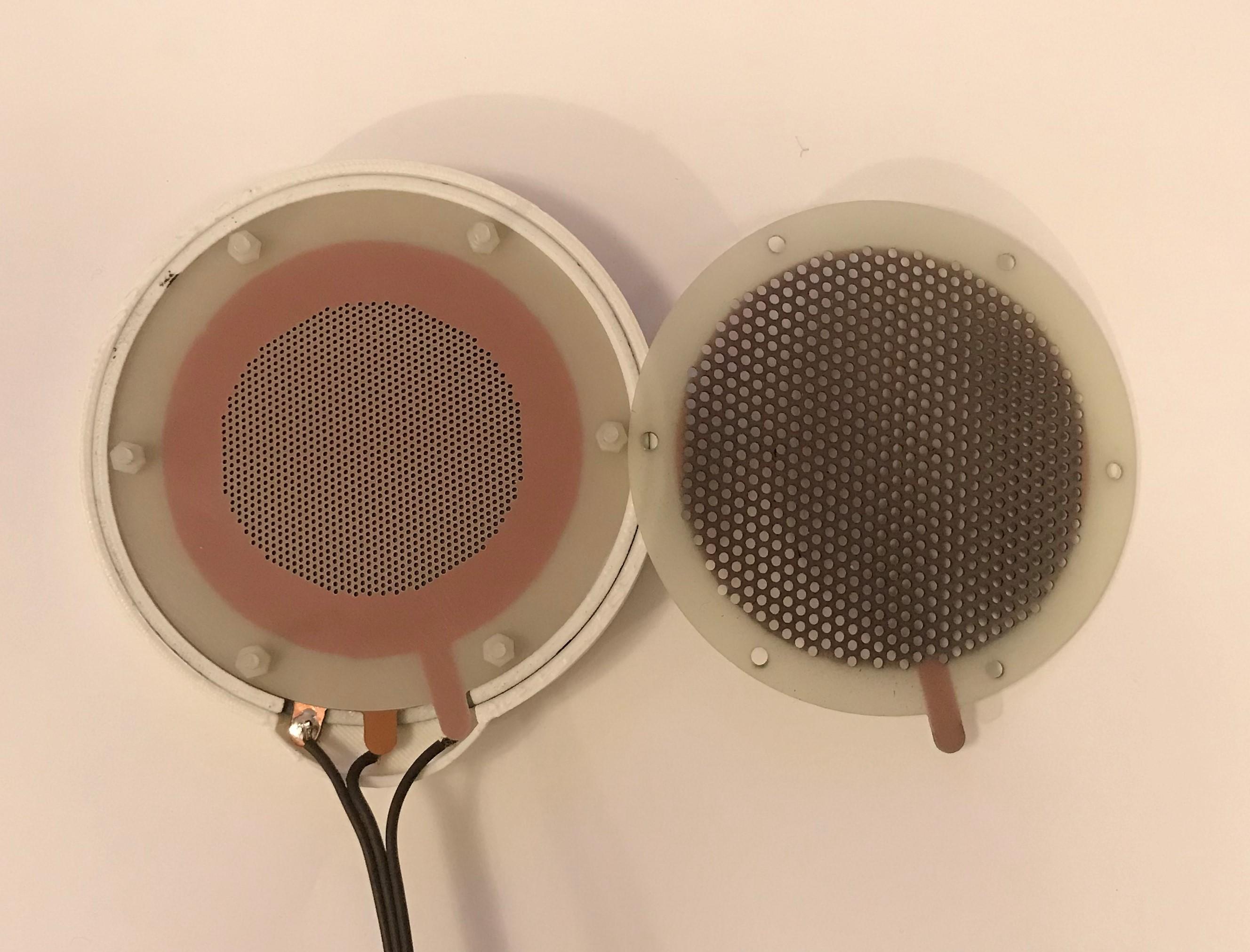
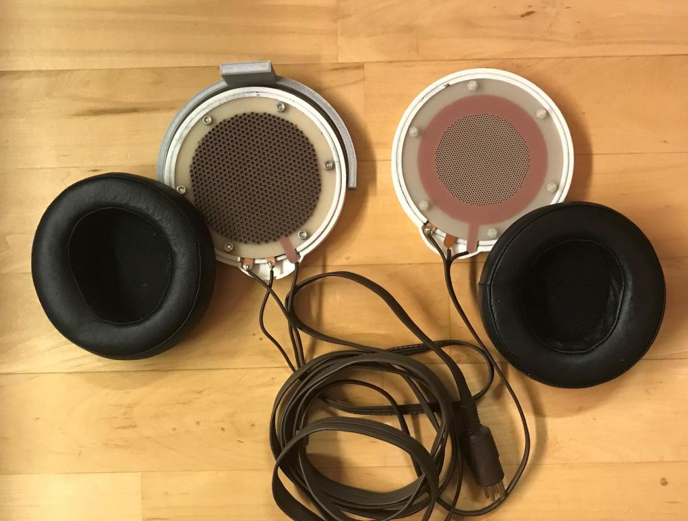 I use 0.5 mm spacers. So far I’ve made just three diaphragms and I have to learn how to get the right tension and also to get a good coating. After a few hours it seem that the new diaphragm is catching up with older one… and they actually are quite alike.Opened up my SR-007 today and checked out the stators. Then I made this (left, stator to the right is the first I made) – it’s almost the same dimensions as the Stax. Diameter of the perforated area is 1.5 mm larger on my stators. Hole diameter is 1.0 mm, 1417 holes. Also made another diaphragm but it plays very soft so the imbalance is total… but it's slowly coming, maybe it needs some time to charge - I don't know. You guys should try this, it's really fun. For information about building electrostatic headphones jump to head-fi and this great thread.
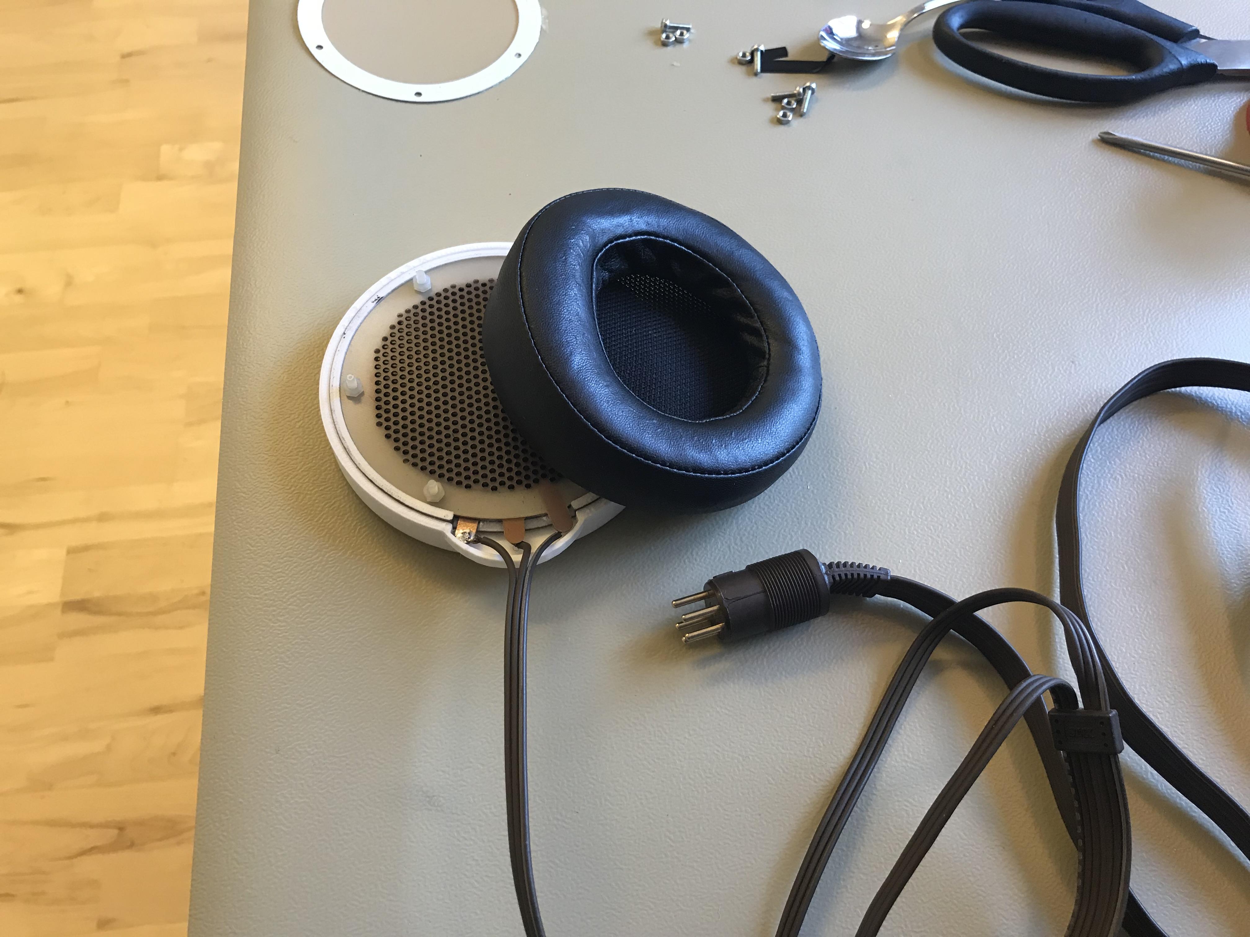
 Listened to this for the first time today. Pad is from a SR-007 and cable from an old Lambda and the rest is home made. The main parts are made with files from Wachara (chinsettawong). Many thanks. A lot more has to be done before it’s a decent headphone.
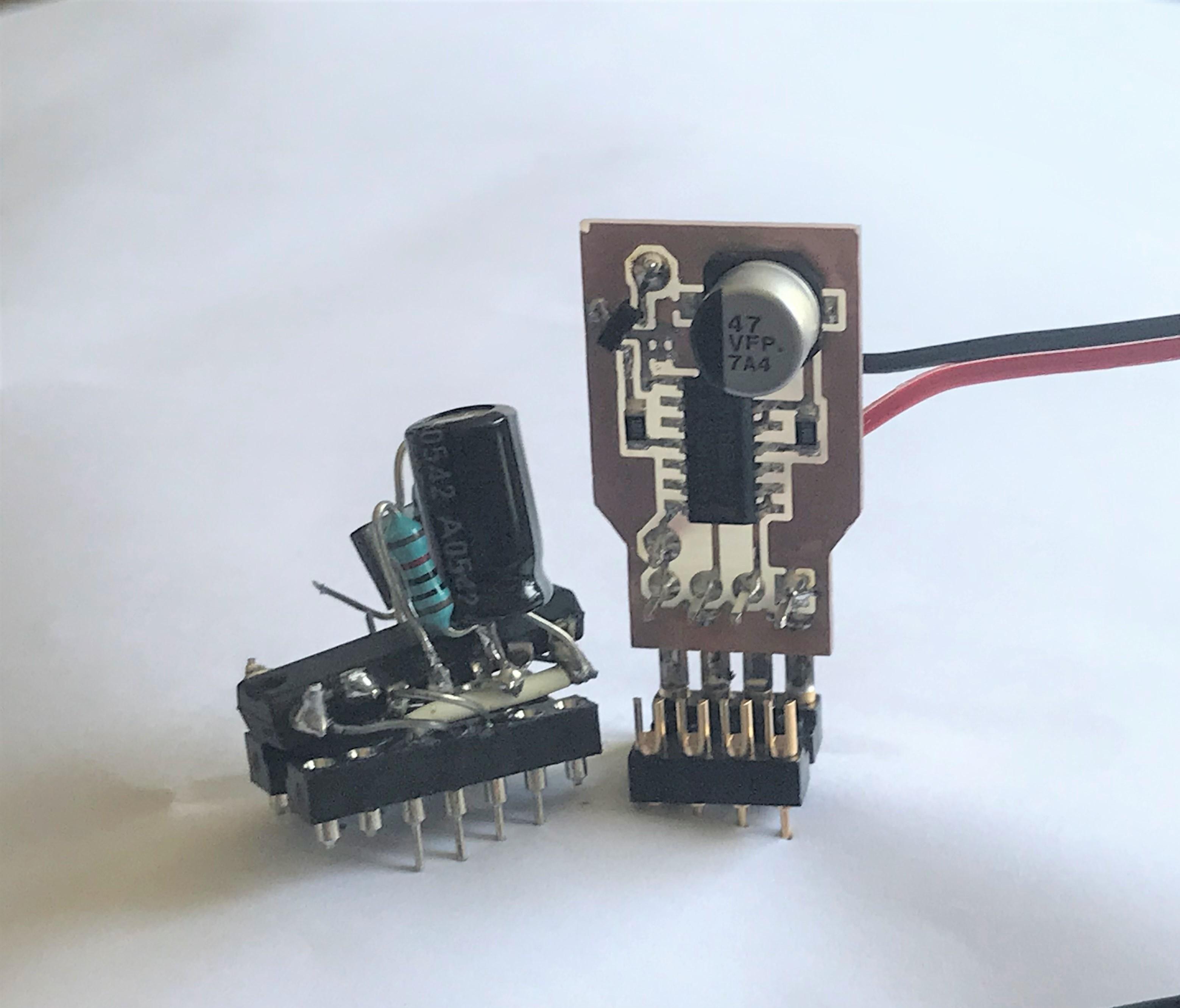
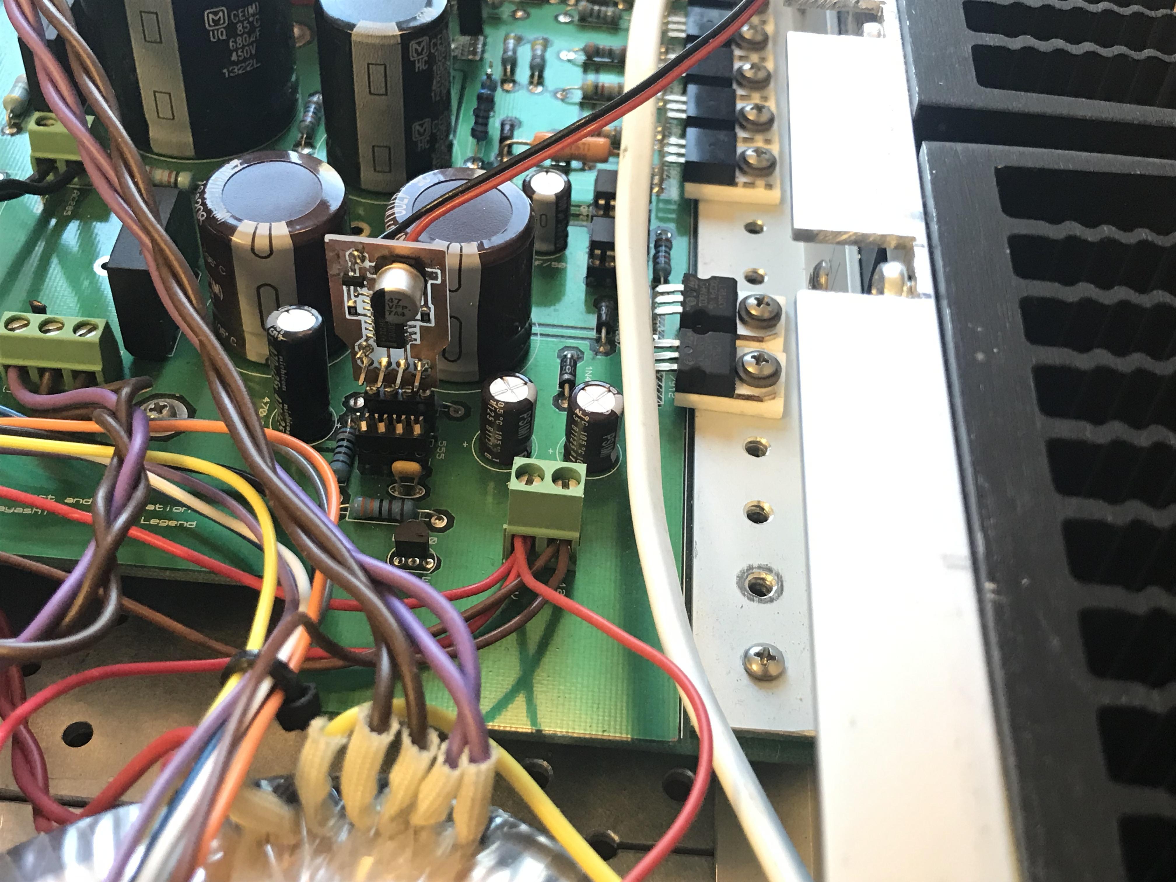
 https://en.wikipedia.org/wiki/Aluminium_oxideWow, I like that Scanivox box – beautiful.We have to keep this thread alive, don’t we. New version of 4093 based timer for T2 PSU - replaces the 555 IC. Makes a LED flashing during pre-heat and get steady when high voltages kicks in. Old to the left and new to the right. New in place in the T2 power supply.
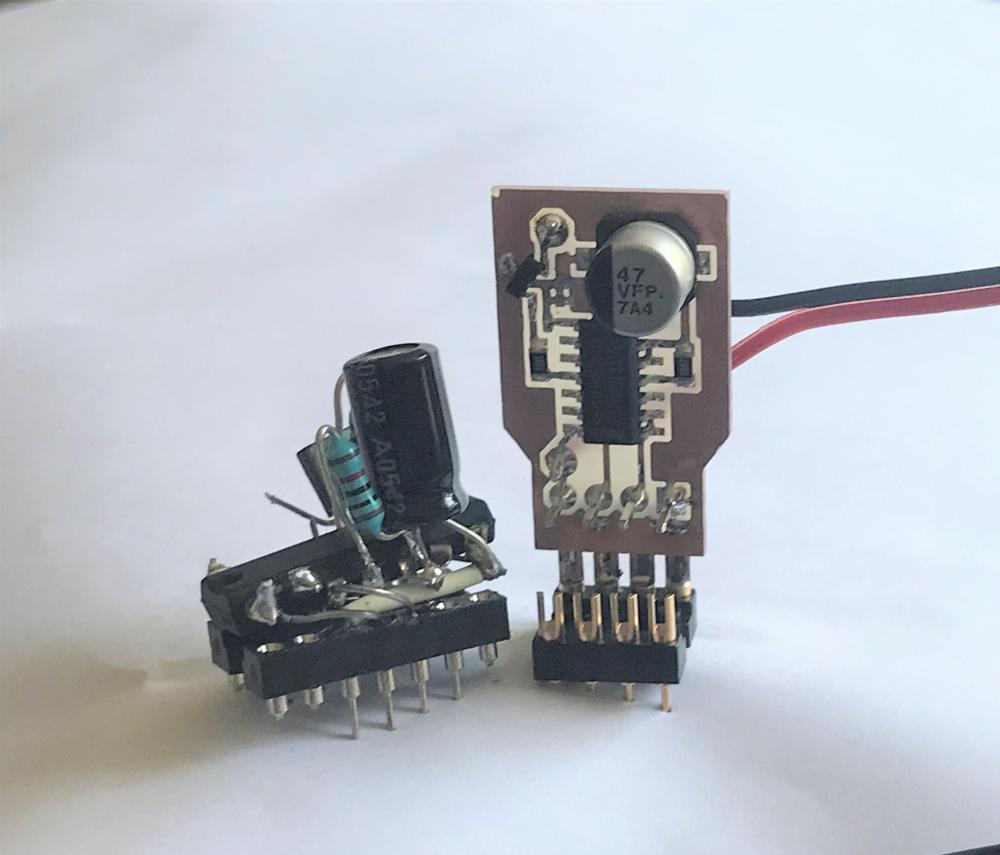
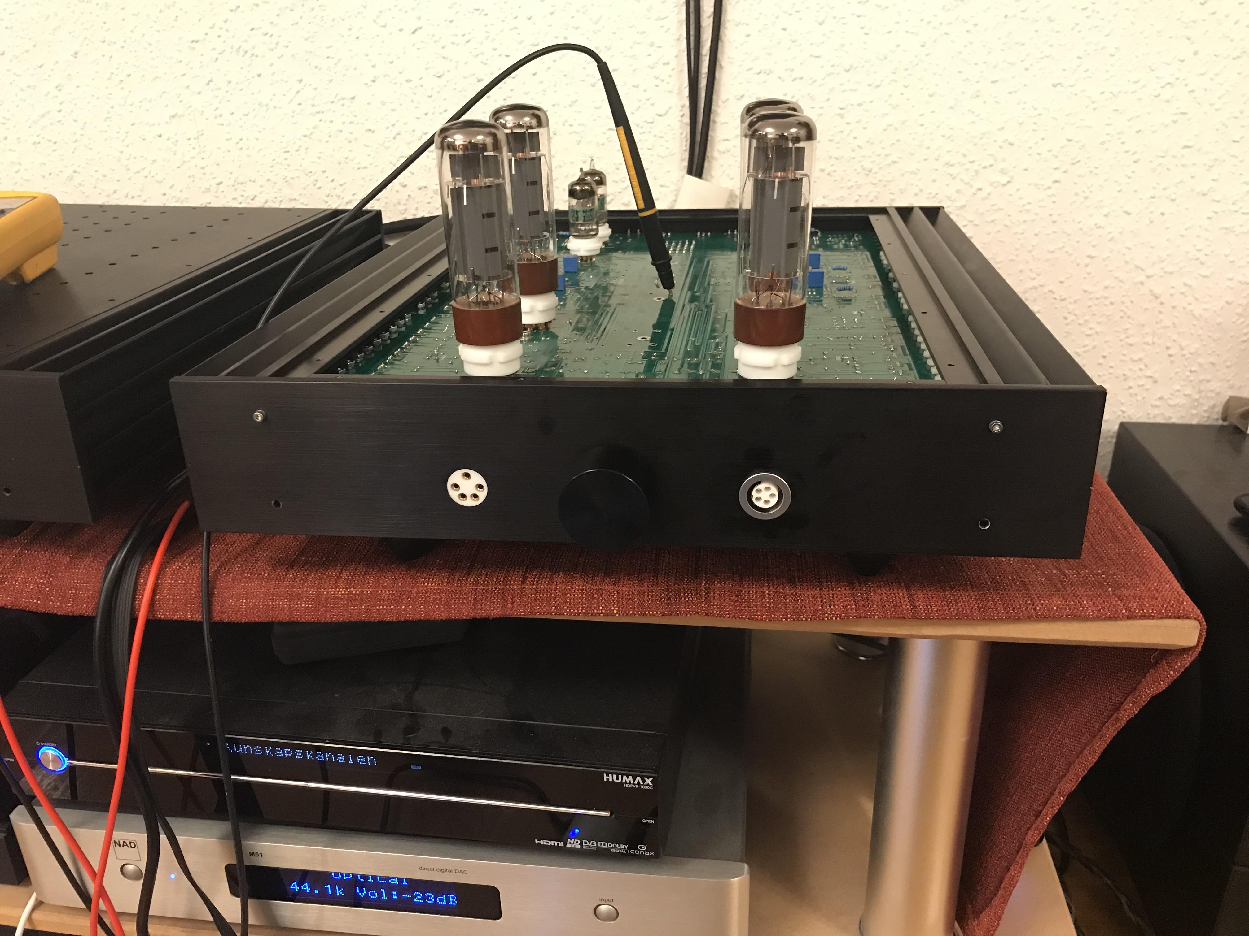
 Did this today. Dual headphone connectors. Not my amplifier.
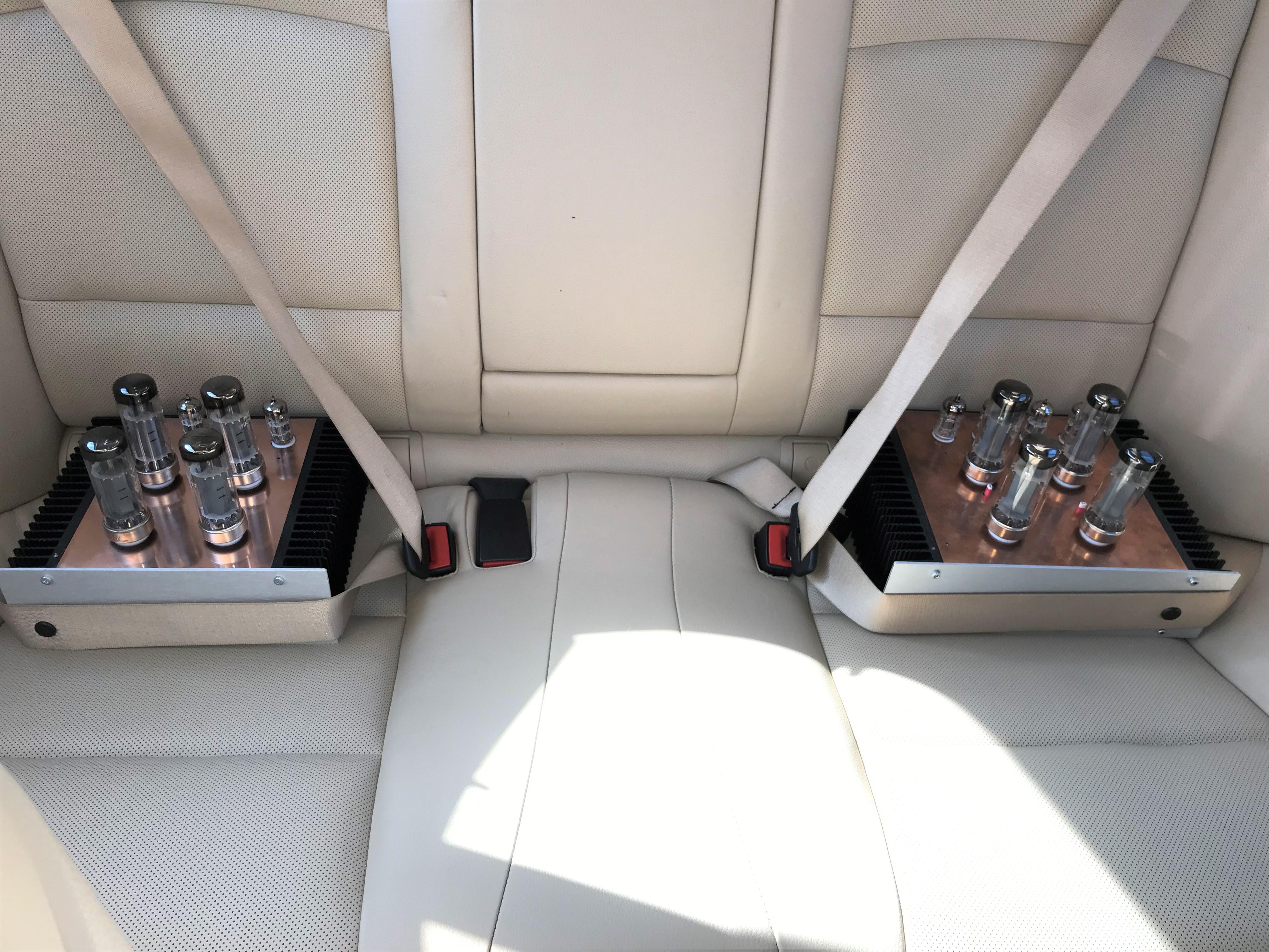
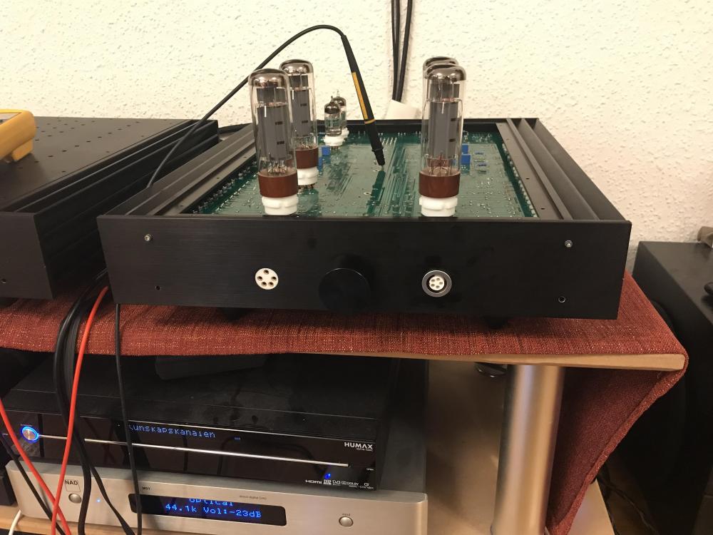 Lovely to see a KGSShv with on board heat sinks again!


Important Information
By using this site, you agree to our Terms of Use.
Account
Navigation
Search
Configure browser push notifications
Chrome (Android)
- Tap the lock icon next to the address bar.
- Tap Permissions → Notifications.
- Adjust your preference.
Chrome (Desktop)
- Click the padlock icon in the address bar.
- Select Site settings.
- Find Notifications and adjust your preference.
Safari (iOS 16.4+)
- Ensure the site is installed via Add to Home Screen.
- Open Settings App → Notifications.
- Find your app name and adjust your preference.
Safari (macOS)
- Go to Safari → Preferences.
- Click the Websites tab.
- Select Notifications in the sidebar.
- Find this website and adjust your preference.
Edge (Android)
- Tap the lock icon next to the address bar.
- Tap Permissions.
- Find Notifications and adjust your preference.
Edge (Desktop)
- Click the padlock icon in the address bar.
- Click Permissions for this site.
- Find Notifications and adjust your preference.
Firefox (Android)
- Go to Settings → Site permissions.
- Tap Notifications.
- Find this site in the list and adjust your preference.
Firefox (Desktop)
- Open Firefox Settings.
- Search for Notifications.
- Find this site in the list and adjust your preference.