JoaMat
-
Posts
1,558 -
Joined
-
Last visited
-
Days Won
16
Content Type
Profiles
Forums
Events
Everything posted by JoaMat
-
Amen. I wrote that? wow! I’ve been looking through the window into your wonderful world of DIY headphones for years. Thanks for inviting me. The number is set due to necessity. Imagine our small living room and 29 full sized electrostatic amplifiers with associated power supplies. Practical impossible. As long as Kevin, Kerry and others are constantly providing us with new projects the space of our apartment is my bottleneck.
-
All may cases look the same. The grounded grid is still untouched. This one has been serving as KGSShv and Blue Hawaii. Have an agreement. - number of working amplifier should be constant. New amp demands a sacrifice. My closet. T2 is my preferred amplifier. The rest come and go.

-
Yes, single plus double. I’ve a CNC machine. Drilling the board is easy, fast and precise. Milling. Boards are done in a couple of hours. Making the vias and building the two boards together went very smooth. My first attempt - maybe beginners luck.
-
The three layer Carbon has as early said no trimmers. Offset and balance are entirely controlled by servos. The offset servo is the opto version introduced by Kevin some year ago. The balance servo I use was published by Kerry somewhere on Head Case a couple of years ago in a LTspice model. The cascoded current sources used is thanks to James Lin and his SRX revisited. James cascoded current source is now days found in many amplifiers and power supplies here at Head Case. Thank you gentlemen. (If I’ve had a screen printer in my kitchen your names would be on the top silk)
-
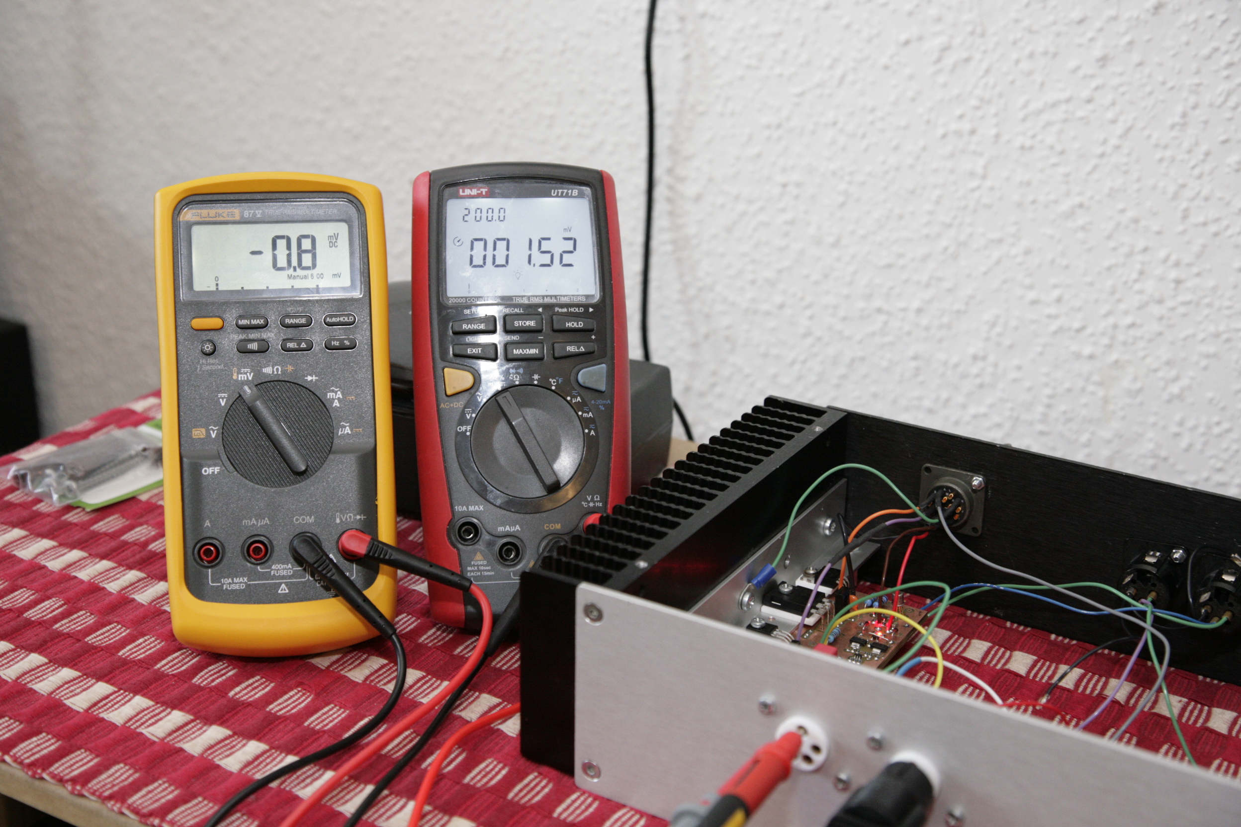
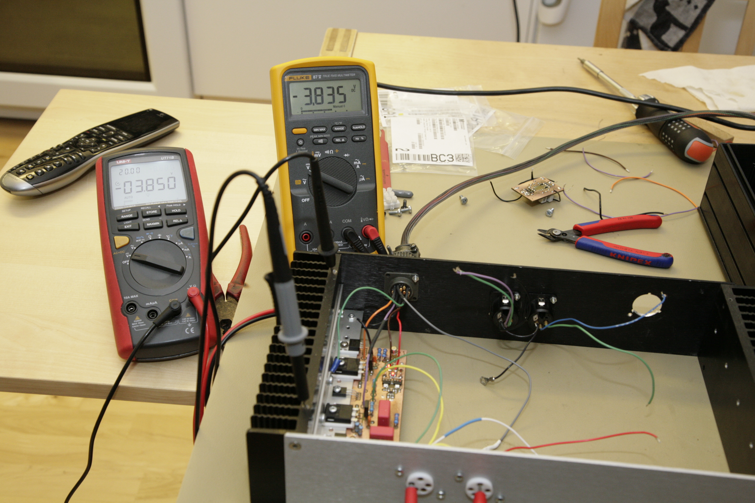
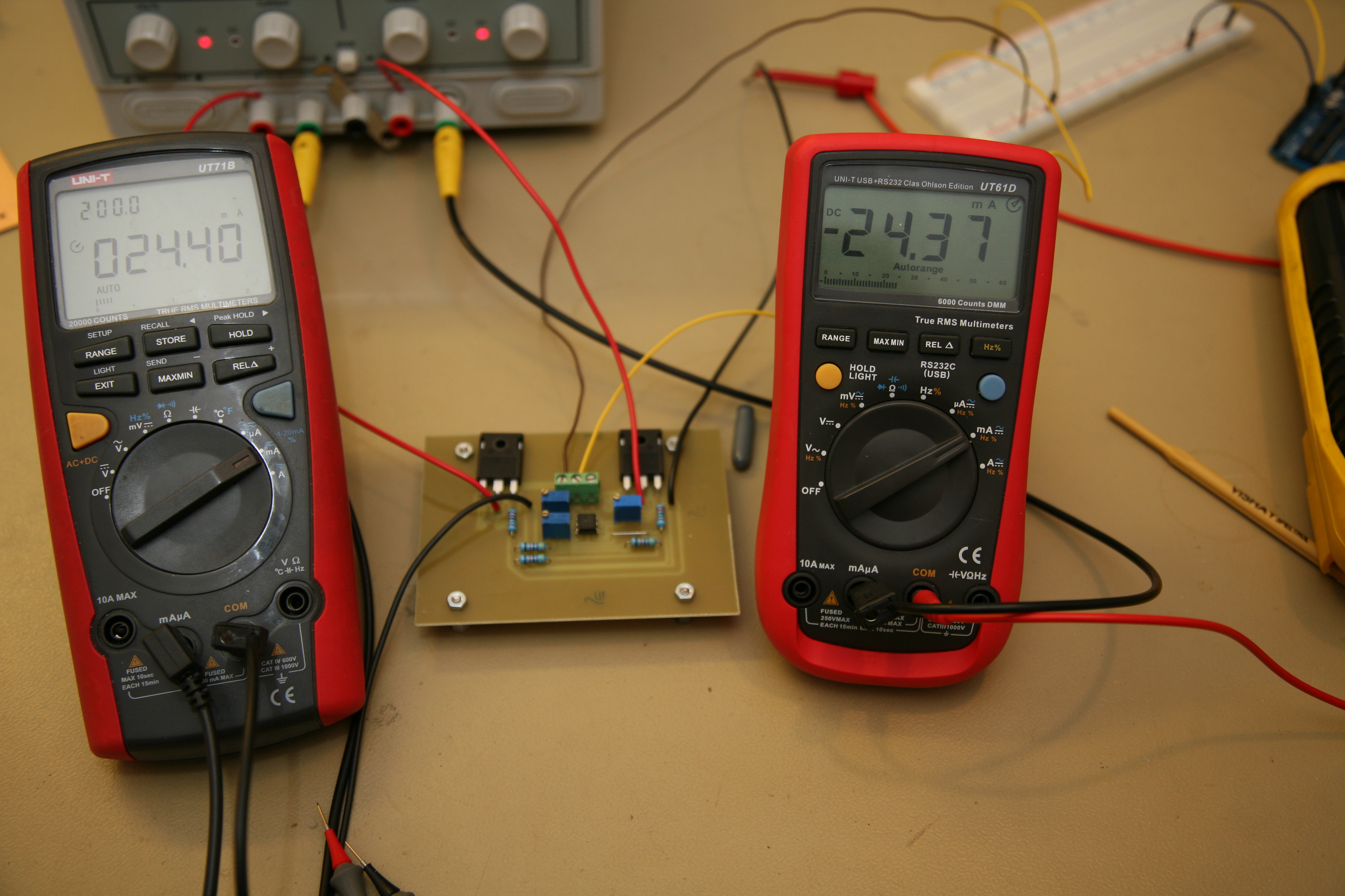
The 3-4 volts offset was a bit of a disappointment. Turned out OP27 was (partly) defect. New OP installed and now I get readings as below. No signal at input and DC at outputs are in mV range. No trimmers, just power up, inhale and all is set.
-
Reality TV..... nhaa. But look at this. Balance is perfect. The offset is shit though - should be zerooooo. Ops Cheers
-
I'm almost ready to connect power. Must say I'm a bit nervous about this......
-
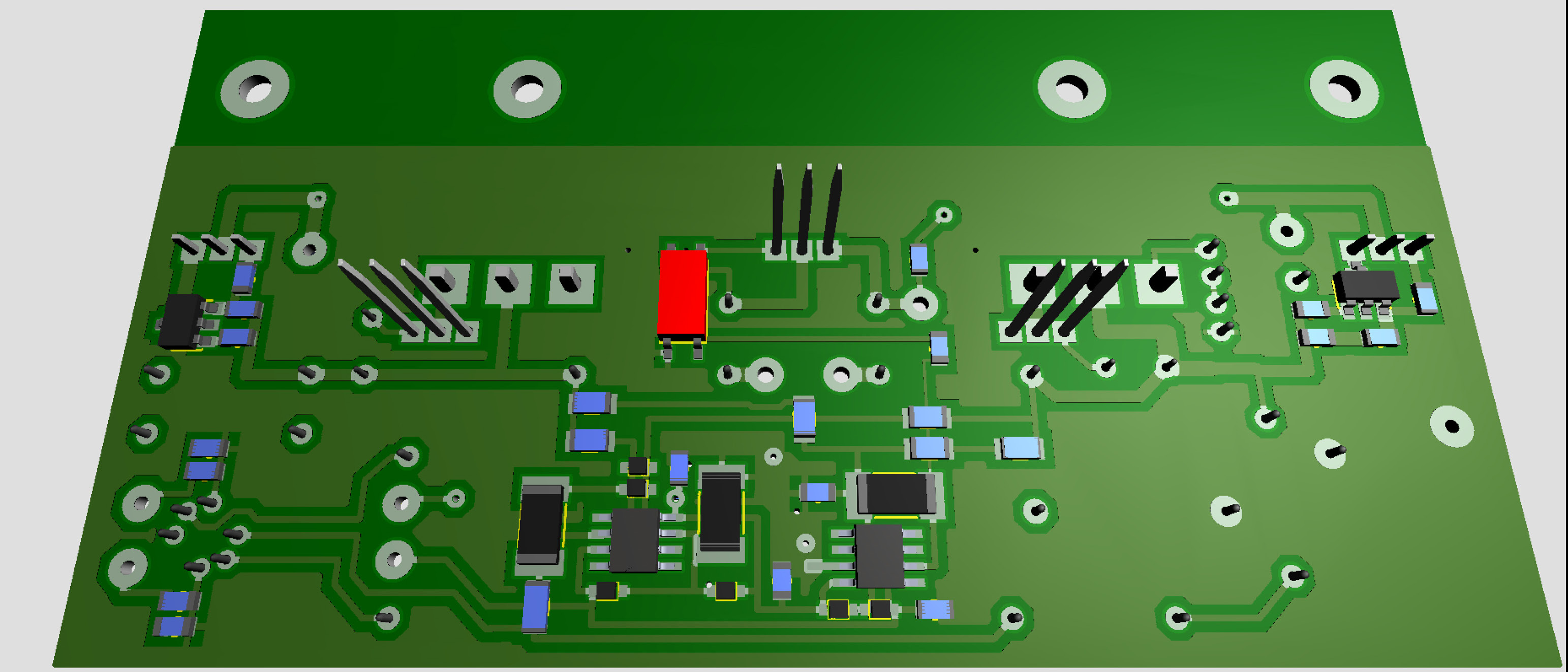
The three layer Carbon is moving forward.
-
If you use GRHV supplies with “switch” – there are all kinds of supplies now days – it’s fairly easy to arrange a delay, even with a flashing led during pre-heat and steady in operation mode.
-
Great thing the usb port - makes life easier.
-
I think a delay of 50 - 60 seconds is a good idea.
-
Nice! Seems you are using small heat sinks on 10m90s, dn2540, op27...? IMO absolutely not necessary. And yes - opto sevo is the SERVO to use.
-
Shouldn't 1/2 watt be enough?
-
Have drilled and cut out boards for the three layer Carbon. A bit smaller than the T2.
-
Great, well done!
-
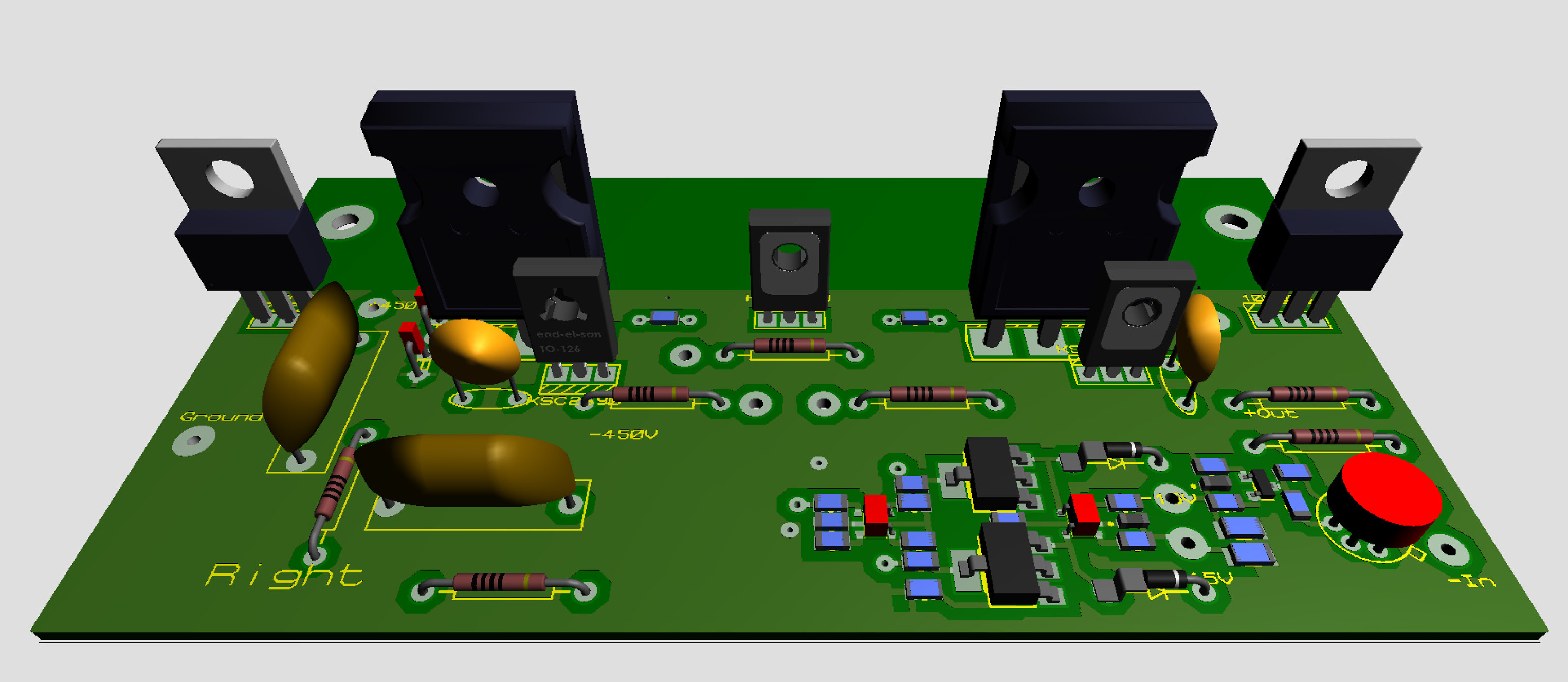
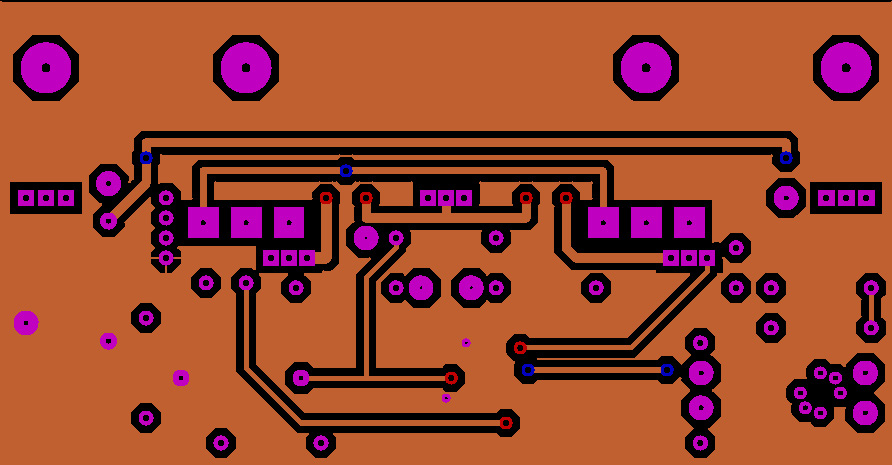
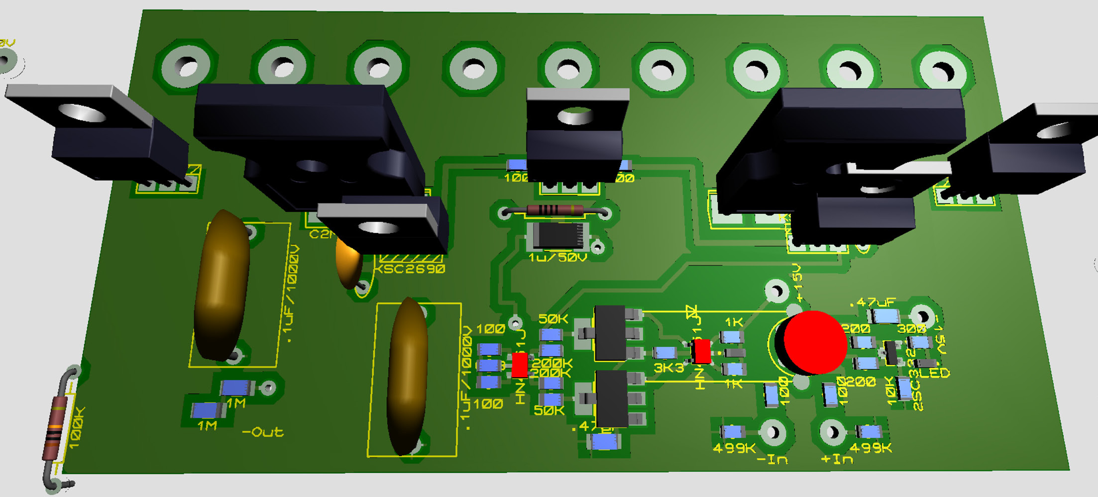
Seems you make great progress, Whitigir. Already one amp working, then one is almost home. Made some more work on the Carbon. Managed to keep it within 4.5 x 2.4 inches. Three layers – will try to do this in kitchen….. For some unknown reason the software flips the to-126 in 3D view. Below: inner layer, and bottom.
-
Another sort guld. Very elegant.
-
Is 3 watts really needed? Max current should be 120mA and through 5 ohms …. not much.
-
Needs more work - a lot. Board size 4.5 in x 2.4 in. No trimmers, servos on bottom.
-
Very much appreciated.
-
Had a pupil once that suggested mV stands for miniVolt. Cute isn’t? Anyhow - this is what I’ve done today: Current in mA – milliampere. Regarding Watt. You know what Miniwatt is?
-
= 3000 minivolts
-
Positive: 10uF, 1uF, 4x10uF and 5x0ohm resistors for voltage setting. Negative: 10uF, 1uF, 4x10uF and 89ohms, AOT, 1M43, 10nF.
-
 Just switching to 100 watts resistors will that protect us from exploding output board and associated PSUs?