GrindingThud
Returning Member
-
Joined
-
Last visited
Everything posted by GrindingThud
-
Nice collection. I have a 15C but not used it in years...makes me want to break it out.
-
-
Cool!
-
Wow, it's almost invisible to the eye, but checks easy with the DMM. I thought someone had swapped my obecalp prescription....now I know what was going on.
-
Nice!
-
Use a battery and DC as input, it's a DC amp. Measure the output voltage with a meter....you'll see whatever imbalance you have, including effects of the pot.
-
Ooo, that's small enough it makes me want one. Nice layout.
-
Listening to the showreel of last nights show again....really like this one.
-
Ooo, Zero7...
-
I unscrewed and wiggled the xformer then tightened back up. Took care of most of it.
-
Thanks!
-
For CFA2 is it possible to up the gain to 7? I've not figured out how to do it with this circuit.
-
Ooo, Nutella melt looks yummy!
-
Nice photos VPI! That was me with the KG pile. It was way noisier than normal, hard to analyze anything.
-
Ah, looks a little different than what I thought. I'll get the single ended version cased up before I move to the balanced one, which I think I will. Whats a few more boards. Got a lot of puzzled faces at the meet today.... people somehow expect less when all the guts are hanging out. Once jacked in, it was all smiles and amazement. Most people preferred it to the Krell clone.
-
Omfg, I'm going to need a bigger case. Can you do the phase splitter as a separate board so I can add to what I've got?
-
I'll have the working unit at the MD/DC/VA meet tomorrow. Amp sounds great! http://www.head-fi.org/t/754656/dc-area-head-fi-meet-george-mason-regional-library-sunday-april-12-2015-noon-5-pm George Mason Regional Library George Mason Meeting Room (on your left right after the entrance). Date: SUNDAY. APRIL 12, 2015 Time: 12:00 Noon to 5:00 PM Location: 7001 Little River Turnpike, Annandale, VA 22003
-
Single ended input (negative grounded) I get +7.9V at that junction. There are two LM339 in the circuit and both are wired. Takes a few seconds to ramp up from around -10V and trigger the relay on. Pins 1, 2, 13, and 14 of the LM339 should all be at 9V or so when output relay on.
-
It's on a big sink, so it does not get hot. It does get warm after an hour or so. On the angle alone, it gets very hot in a few minutes.
-
Wondering if I should put a small series resistor on the input of the amp. At the pot extremes, I'm experiencing some noise, especially when maxxed. Of course it's never that high when listening, or my head would explode. This amp is spectacular!
-
Now I'm way behind.
-
Indeed! Catching it again now before Marvel comes on.
-
This circuit should work single ended with both negative inputs grounded, yes? I'm planning on putting it in the CFA2.
-
4pin and mo bigger resistor it will be. Agree that resistor never should have opened...I'm thinking they may have been defective in some way or there is enough capacitance to spike it open. Never smoked one in the KSA5 clone or the SS Dynalo. Will go to wire wound non-inductives. I still may be able to get this together enough to bring to a meet next week in VA. Thanks for the kind words....it's a hobby for me and a bit fun.
-
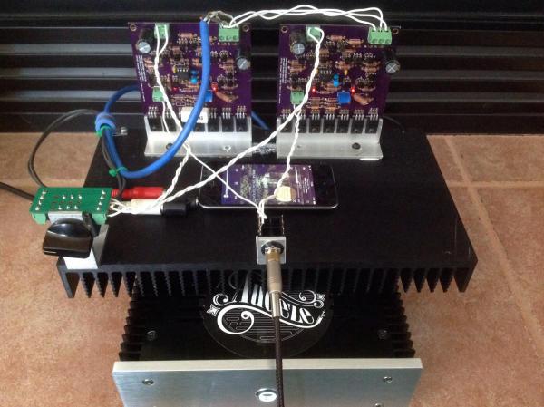
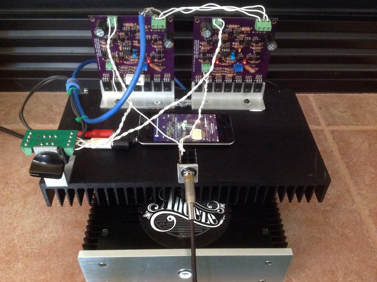
I'm going to put my wow hat on for this one. It sounds great. Tried it with cheesy iems and its dead quiet with the KSA5 psu. I've got my LCD2.2s on it and it's super transparent. Maybe could use a tad more gain. All was good for quite a while until I lost a 1ohm resistor....I stuffed a 10 in there (all I had) and biased a little lower until replacement comes in. Not sure what happened...maybe shorting the TRS..keeping an eye on that. This may be my new favorite once I get it boxed up. Edit...ok, duplicated the failure and these go nuclear when the TRS is shorted on insert: http://www.mouser.com/Search/ProductDetail.aspx?R=CPF11R0000FKEE6virtualkey61300000virtualkey71-CPF11R0000FKEE6 Need to get better resistors in that position. I'd have thunk these would have survived at 1W...guess not. Keeping an eye on Q27/28 also. They are quite hot to the touch. Updated photo....anchored everything to my test platform.