GrindingThud
Returning Member
-
Joined
-
Last visited
Everything posted by GrindingThud
-
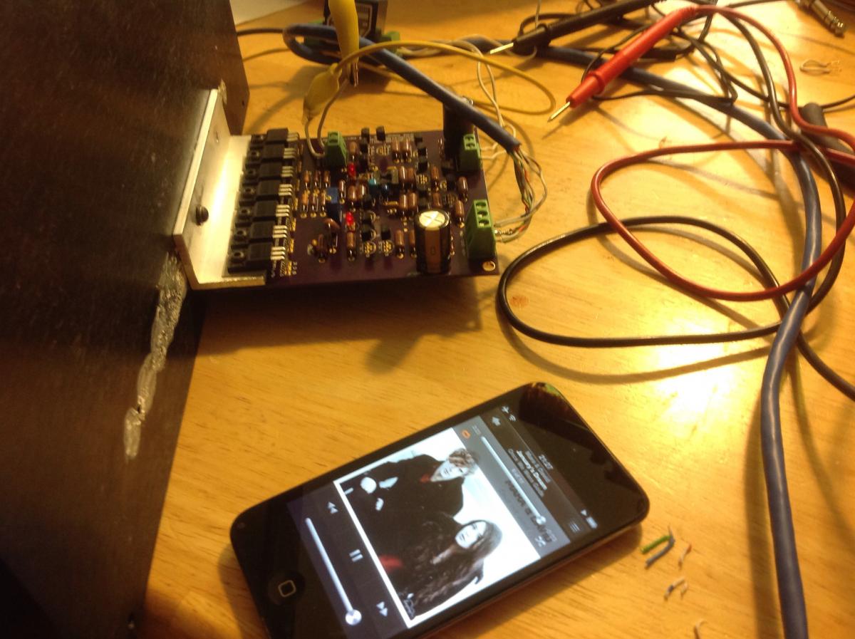
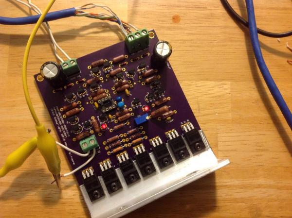
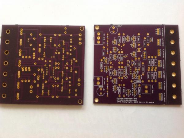
2nd board is done and mounted. Will test after I eat and then listen in stereo. .
-
Opamp output is sitting at .455V with final amp output settled at 0.1mV with input shorted Driving the input positive or negative with a 1.5V battery (measured at 1.65V) drives pin 6 to +/-20 Output under those conditions is brought to +/-4.68V non-inverting. Without the servo, final output swings +/-5.8, so about 1.2V of correction. Gain is around 3.5
-
Yep, working great now. I used 5K instead of 15 because that's what I had laying around. I might have some 14.7s I'll use on the next board. Q27/28 run a little hot but I think only drop a third of a watt.
-
Oh, shoot, way down there in the chain. Thanks for the clarification, I was thinking about it ass backwards trying to tie it back into the other section!
-
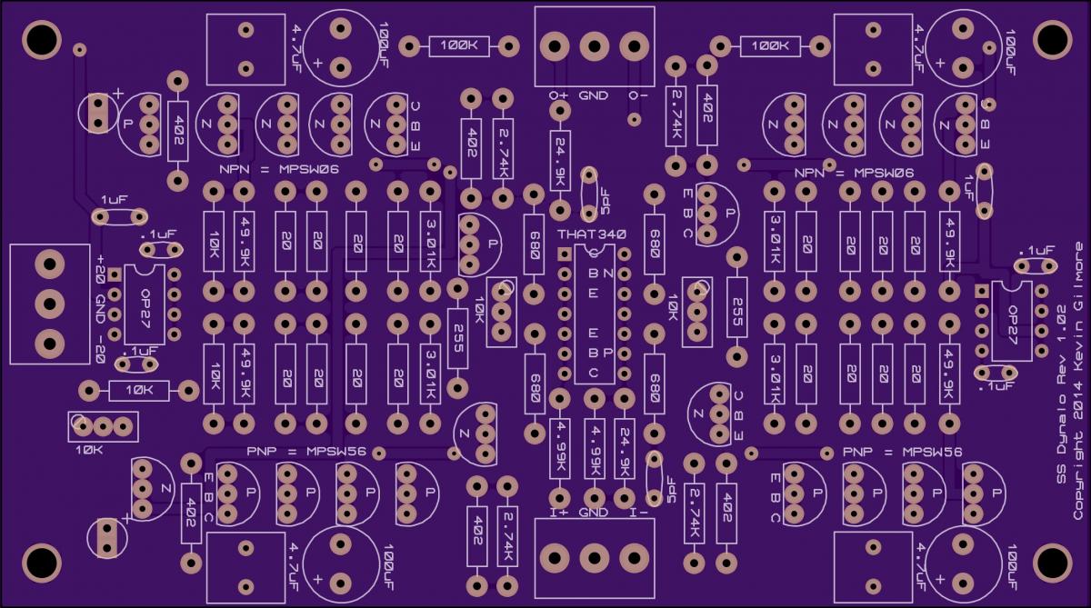
Ok, I'll try the resistors 1st. So I'd tie the top of R4 by Q2 and bottom of R5 by Q4 back to pin 3 via the 5K pair....that will invert it?
-
I was just going to swap pin 2 and 3....easy trace cut. Need to wait til Friday for the mod...too much work during the week.
-
Input pot 10k (shorted for now). I have an interesting issue. I jumpered pin3 to ground (left the offset pins float) on the servo opamp. The output of the amp drifts to just under 2v offset (opamp pin 6 drifts to -19v). Or I can flip it if I drive the output the other way with a battery. -2V offset and 19V pin 6. Is the polarity of the feedback correct?
-
http://www.mouser.com/Search/ProductDetail.aspx?R=RDEC71E476MWK1C03Bvirtualkey64800000virtualkey81-RDEC71E476MWK1C3B http://www.mouser.com/Search/ProductDetail.aspx?R=FK20X7S1H475Kvirtualkey52130000virtualkey810-FK20X7S1H475K
-
It lives! Without the servo (still need to add the jumper) it's only got a few mV offset and is dead quiet with cheesy iems Now I've got to figure out the bias....oh, I think I've got it. 150mA across the 1 ohm. Now I've got to get the second channel built. I think this one may be a winner. I'm observing interesting behavior...seems the bias current changes with input pot position. May be because the servo is out, or could be my input wiring. Driving my headphones in mono it sounds great!

-
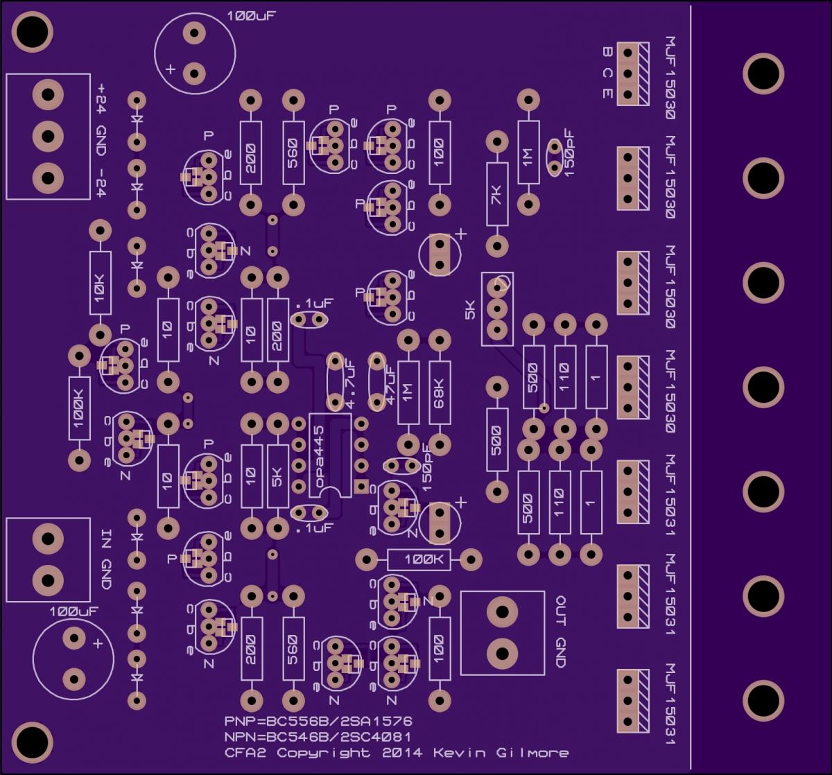
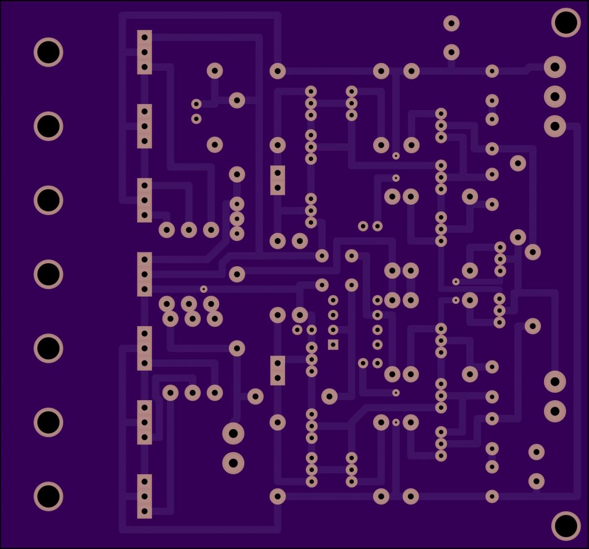
Soldering under way. Possible error on board. In the schematic, the positive input of the opa445 is grounded. On the board, pin3 is not connected to anything. Pins 1, 3, 5, 8 are floating. I plan to run a short jumper from pin3 to the nearby .1uf cap ground if it needs it.
-
Looks like a project weekend! Boards are in. I plan to do one set as throughole and one as SMD. Question...will it mind being run off the KSA 21V supply? My other alternative is the 30V from the Dynahi without modding it.
-
^^ like he said.... I use these: http://www.mouser.com/ProductDetail/ON-Semiconductor/MPSA56RLRMG/?qs=sGAEpiMZZMshyDBzk1%2fWi%2fPUgtclNldl2ZkToUCMhk0%3d
-
-
Like this: http://gilmore.chem.northwestern.edu/kgdynalobalssproduction.pdf
-
Chambord oxidizes pretty quickly after being open and will eventually turn a nasty brown. Cognac will oxidize also. Scotch is somewhere around 6 months or so after opening. Unopened they last indefinitely.
-
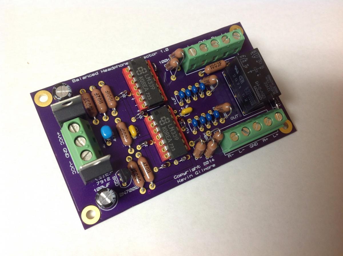
Its running happily in my SuSy Dynalo with no issues that I've noticed. Provides a nice little startup delay and cuts out if I induce DC on the output.
-
Doh...I Must have been dazed by staring at purple on purple for too long.
-
Better batteries than lipstick, Chapstick, or that God forsaken silly putty. Nothing effing worse than silly putty in the dryer! The batteries won't hurt anything, even if they leaked all over, just throw them away even if they work. The could leak later on. If it makes you feel better, wash them again (the sheets not the batteries).
-
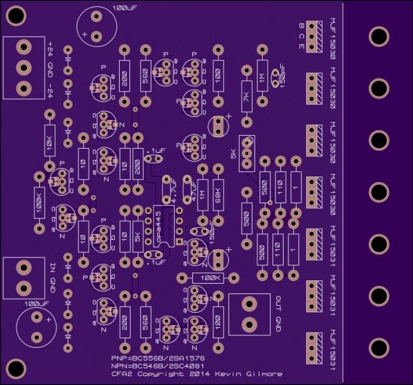
Hand traced and it looks ok to me. Subtle differences in the schematic vs the board: C2 is 100uf in schematic vs 47uf on board. C1 is 4uf in schematic vs 4.7uf on board. The top two tiers of the triple darlington emitter resistors float in the schematic and are output referenced on the board. Also noticed the ground in and out connections, the 100uf and .1uf cap grounds don't have thermals...not sure if you typically use them there or not. What's the gain set to on this one? I having trouble figuring that out. I plan to get a proto board spun when I have time...much more compact than the KSA5.
-
I have those for my pinball machine boards. I might try those on my next build.
-
Have the files been posted for this one yet?
-
Foo! Mistakenly swapped +/- on one of my boards... Fortunately I caught it quick and only the opamp and 7915 smoked. Was a slow day so I decided to do some chassis work and biasing.
-
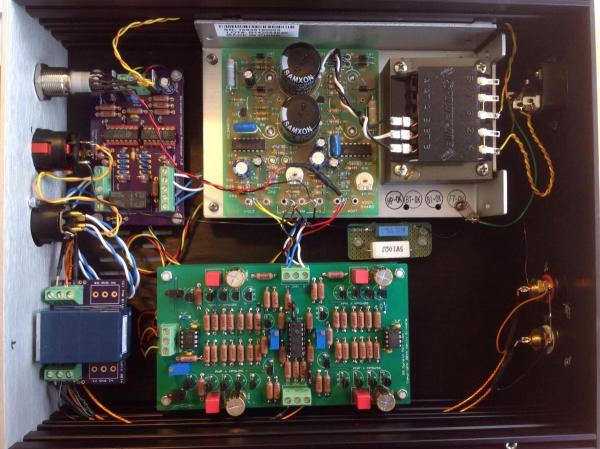
Still have not finished installing the balanced input jacks, but the protector circuit fits nicely in there.
-
Ready for test. 1st install will be in my SuSy Dynalo.

-
Bummed I missed it live...thanks for the link. Would not want to miss a really good one.